length JEEP CJ 1953 Owner's Manual
[x] Cancel search | Manufacturer: JEEP, Model Year: 1953, Model line: CJ, Model: JEEP CJ 1953Pages: 376, PDF Size: 19.96 MB
Page 107 of 376
'Jeep*
UNIVERSAL
SERIES
SERVICE
MANUAL
Dl
Dl-105.
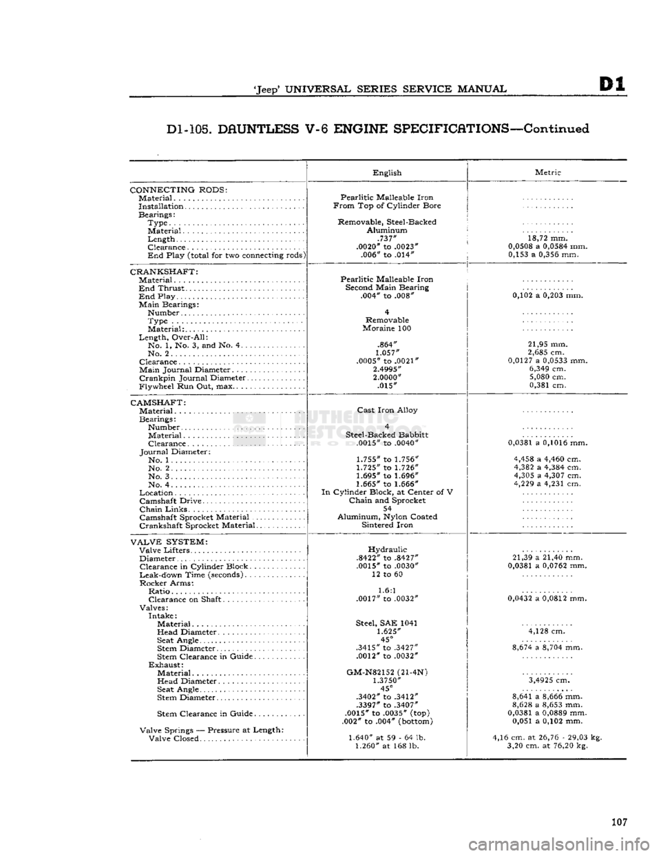
DAUNTLESS
V-6
ENGINE
SPECIFICATIONS—Continued
CONNECTING
RODS:
Material
Installation
Bearings: Type........
Material.
Length Clearance
End
Play
(total
for two
connecting
rods)
CRANKSHAFT:
Material ,
End
Thrust
End
Play
Main
Bearings: Number Type
Material:
Length, Over-All: No. 1, No. 3, and No. 4
No. 2
Clearance
Main
Journal Diameter.
Crankpin
Journal Diameter
Flywheel Run Out, max
CAMSHAFT:
Material
Bearings: Number Material Clearance
Journal
Diameter: No. 1 No. 2
No. 3.
No. 4
Location Camshaft Drive
Chain
Links
Camshaft Sprocket Material
Crankshaft Sprocket Material
VALVE
SYSTEM:
Valve Lifters Diameter Clearance in Cylinder Block
Leak-down Time
(seconds)
Rocker Arms: Ratio Clearance on Shaft
Valves: Intake: Material
Head Diameter
Seat
Angle
Stem
Diameter
Stem
Clearance in Guide
Exhaust:
Material Head Diameter
Seat
Angle
Stem
Diameter
Stem
Clearance in Guide
Valve Springs — Pressure at Length: Valve Closed English
Pearlitic Malleable Iron
From
Top of Cylinder Bore
Removable, Steel-Backed Aluminum .737"
.0020"
to
.0023"
.006" to .014" Metric
18,72 mm.
0,0508
a
0,0584
mm. 0,153 a
0,356
mm.
Pearlitic Malleable Iron
Second
Main Bearing .004" to .008"
Removable
Moraine 100
.864"
1.057"
.0005"
to
.0021"
2.4995"
2.0000"
.015" 0,102 a
0,203
mm.
21,95 mm.
2,685
cm.
0,0127
a
0,0533
mm.
6,349
cm.
5,080
cm.
0,381 cm.
Cast
Iron Alloy
Steel-Backed Babbitt
.0015"
to
.0040"
1.755"
to
1.756"
1.725"
to
1.726"
1.695"
to
1.696"
1.665"
to
1.666"
In
Cylinder Block, at Center of V
Chain
and Sprocket 54
Aluminum,
Nylon
Coated Sintered Iron
0,0381
a
0,1016
mm.
4,458
a
4,460
cm.
4,382
a
4,384
cm.
4,305
a
4,307
cm.
4,229
a 4,231 cm.
Hydraulic
.8422"
to
.8427"
.0015"
to
.0030"
12 to 60
1.6:1
.0017"
to
.0032"
Steel,
SAE 1041
1.625"
45°
.3415"
to
.3427"
.0012"
to
.0032"
GM-N82152
(21-4N)
1.3750"
45°
.3402"
to
.3412"
.3397"
to
.3407"
.0015"
to
.0035"
(top)
.002" to .004"
(bottom)
1.640"
at 59 - 64 lb.
1.260"
at 168 lb. 21,39 a 21,40 mm.
0,0381
a
0,0762
mm.
0,0432
a
0,0812
mm. 4,128 cm.
8,674
a
8,704
mm.
3,4925
cm.
8,641 a
8,666
mm.
8,628
a
8,653
mm.
0,0381
a
0,0889
mm. 0,051 a 0,102 mm.
4,16 cm. at
26,76
-
29,03
kg. 3,20 cm. at
76,20
kg.
107
Page 131 of 376
'Jeep'
UNIVERSAL SERIES SERVICE
MANUAL
E
possibility of vapor lock by keeping cool fuel from
the tank constantly circulating through the fuel
pump.
Fuel
pump pressure at carburetor (inlet) on Daunt
less
V6-225
engine
should be 3% lbs.
[0,264
kgm-cm2] minimum at idle with the vapor return
hose
squeezed off. With the vapor return
hose
open
pump pressure should be 2j^ lbs. [0,176 kg-cm2]
minimum.
The
Dauntless V-6
engine
is equipped with a sealed
unit,
non-repairable, single-action fuel pump (Fig.
E-33).
Note:
All Dauntless V-6
engines
are equipped with
a
throw-away can-type gasoline filter installed in
the fuel line
between
the fuel pump and the
car
buretor.
This
unit must be replaced every
12,000
miles
[19.200
km.] of vehicle operation.
E-68.
Fuel
Pump Removal
To
remove the fuel pump from the Dauntless V-6
engine, disconnect the fuel inlet, fuel
outlet
and fuel return lines from the pump. Remove the two
fuel pump body attaching cap screws and lock
washers.
Pull
the fuel filter bracket free and remove the pump and gasket. Discard pump and gasket.
Install
new pump in reverse procedure of removal.
E-69.
AIR
CLEANER
Servicing
of the air cleaner is properly taken care of as part of the periodic lubrication and servicing of the vehicle. For this reason, air cleaner servicing
information is given in the Lubrication Section.
Refer
to and follow the instructions given there.
E-70. ACCELERATOR LINKAGE
The
accelerator linkage is properly adjusted when
the vehicle leaves the factory. However, in time
components parts
will
become
worn and require re
adjustment to maintain a smooth even control of
engine
speed. On Models equipped with F4
engines
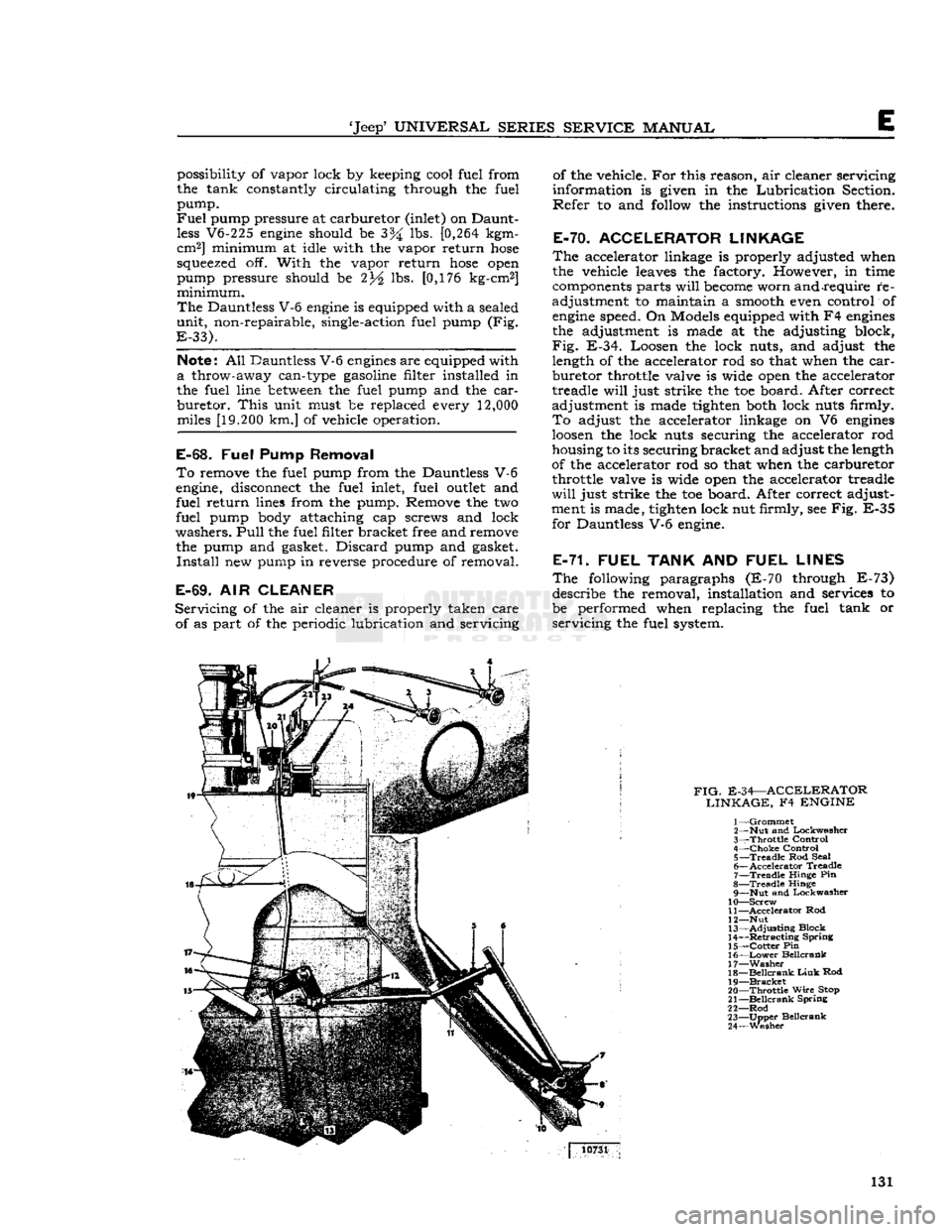
the adjustment is made at the adjusting block,
Fig.
E-34. Loosen the lock nuts, and adjust the length of the accelerator rod so that when the
car
buretor throttle valve is wide open the accelerator
treadle
will
just strike the toe board. After correct
adjustment is made tighten both lock nuts firmly.
To
adjust the accelerator linkage on V6
engines
loosen
the lock nuts securing the accelerator rod
housing to its securing bracket and adjust the length
of the accelerator rod so that when the carburetor throttle valve is wide open the accelerator treadle
will
just strike the toe board. After correct adjust
ment is made, tighten lock nut firmly, see Fig. E-35 for Dauntless V-6 engine.
E-71. FUEL
TANK
AND
FUEL LINES
The
following paragraphs (E-70 through E-73) describe the removal, installation and services to
be performed when replacing the fuel tank or
servicing
the fuel system.
FIG.
E-34—ACCELERATOR LINKAGE,
F4
ENGINE
1—
Grommet
2— Nut and Lockwasher
3—
Throttle
Control
4—
Choke
Control 5—
Treadle
Rod Seal
6—
Accelerator
Treadle
7—
Treadle
Hinge Pin
8—
Treadle
Hinge 9— Nut and Lockwasher
10—
Screw
11—
Accelerator
Rod
12— Nut
13—
Adjusting
Block
14—
Retracting
Spring
15—
Cotter
Pin
16—
Lower
Beilcrank
17—
Washer
18—
Beilcrank
Link
Rod
19—
Bracket
20—
Throttle
Wire
Stop
21—
Beilcrank
Spring
22—
Rod
23—
Upper
Beilcrank
24—
Wesher
10731
131
Page 145 of 376
'Jeep'
UNIVERSAL
SERIES SERVICE
MANUAL
Fl
b. Connect tachometer to
engine.
c.
Warm
up
engine
and stabilize temperatures.
d.
Adjust
engine
idle to
speed
desired, using throt
tle idle
speed
adjusting screw.
e.
Carburetors without Idle
Limiter
Cap turn idle mixture screws out (counterclockwise) until a
loss
of
engine
speed
is indicated; then, slowly turn mix
ture screw in (clockwise-leaner) until maximum
speed
(RPM) is reached. Continue turning in (clockwise) until
speed
begins
to drop; turn mixture
adjustment back out (counterclockwise-richer) un
til
maximum
speed
is just regained at a "lean as
possible" mixture adjustment.
Fl-14.
Distributor
Check
the distributor number for proper appli
cation.
Check
the distributor cam dwell angle and
point condition and adjust to specifications or re place as required. (Specifications listed at the end
of this section)
Check
ignition timing and set at
0°
or
TDC.
Fl-15.
Anti-iackfire
Diverter Valve
The
anti-backfire valve remains closed
except
when
the throttle is closed rapidly from an
open
position.
To
check the valve for proper operation, accelerate
the
engine
in neutral, allowing the throttle to
close
rapidly.
The valve is operating satisfactorily when
no exhaust system backfire occurs. A further check
to determine whether the valve is functioning can be made by removing from the anti-backfire valve
the large
hose
Which
connects to the check valve.
Accelerate the
engine
to allow the throttle to
close
rapidly.
The valve is operating satisfactorily if a
momentary interruption of rushing air is audible.
Fl-16.
Check Valve
The
check valve prevents the reverse flow of ex
haust
gases
to the pump in the
event
the pump
should, for any reason,
become
inoperative or should exhaust pressure ever
exceed
pump pressure.
To
check this valve for proper operation, remove the air supply
hose
from the pump at the
distri
bution manifold.
With
the
engine
running, listen for exhaust leakage at the check valve which is
connected to the distribution manifold.
Fl-17.
Air
Pump
Check
for proper drive belt tension with belt tension
gauge
W-283. The belt strand tension should be
50-60
pounds on a belt with previous service, meas
ured
on the
longest
accessible span
between
two pulleys. When installing a new belt, adjust the
tension to
60-80
pounds tension. DO NOT PRY
ON
THE DIE
CAST
PUMP
HOUSING.
To
check the pump for proper operation, remove the air
outlet
hose
at the pump.
With
the
engine
running,
air discharge should be
felt
at the pump
outlet
opening. The pump
outlet
air pressure, as determined by the relief valve, is preset and is not
adjustable.
The
air pump
rear
cover assembly, housing the pressed in inlet and discharge tubes, and the pres
sure relief valve are the only pump
components
recommended for service replacement. These parts
are
to be replaced only when damaged as a result
of handling or in the
event
the relief valve was
tampered with.
Fl-18.
Carburetor
Air
Cleaner
Every
6000
miles
[9,600
km.] clean the inside
sur
face at the sump and
refill
to indicated oil level with
SAE
40 or 50
engine
oil
above
32 F; SAE 20
below
32 F. Wash filter
element
in kerosene and
drain.
Reassemble the air cleaner.
More
frequent cleaning and replacement is advis able when the car is operated in dusty areas or on
unpaved roads. Accumulated dirt restricts air flow,
reducing fuel
economy
and performance.
Fl-19.
REMOVAL
PROCEDURES
The
following paragraphs
give
the procedures for removing the major units of the Exhaust Emission
Control
System and the required equipment
needed.
Fl-20.
Air
Pump
Loosen
the air pump adjusting strap to facilitate
drive
belt removal. Remove the air pump air dis
charge hose(s) and air filter attachment. Separate
the air pump from its mounting bracket. At time of installation, torque tighten the air pump mounting
bolts
to
30-40
lbs-ft. [4,15 a 5,53 kg-m.]. Adjust
the belt strand tension to
50-60
pounds on a belt
with previous service and
60-80
pounds on a new
belt.
Fl-21.
Anti-Backfire
Diverter Valve
The
anti-backfire diverter valve removal requires disconnecting the
hoses
and bracket to
engine
at
taching screws.
Fl-22.
Air
Distribution
Manifold
and
Injection Tubes
In
order to remove the air distribution manifold
without bending the tubing, which could result in
fractures
or leakage, it is necessary to remove the
exhaust manifold as an assembly from the
engine.
After
the exhaust manifold assembly is removed
from
the
engine,
place the manifold in a vise and
loosen
the air distribution manifold
tube
retaining nuts at each cylinder exhaust port. Tap the injec
tion
tubes
lightly to allow the air distribution mani
fold to be pulled away partially from the exhaust manifold. The stainless steel injection
tubes
in the
exhaust manifold may have
become
partially fused
to the air distribution manifold and, therefore, may
require
application of heat to the joint in order to
separate. While applying heat to the joint, rotate
the injection
tubes
with pliers being careful not to
damage the
tubes
by applying excessive force.
At
time of installation, the air injection
tubes
must
be positioned into the exhaust manifold prior to
placing the exhaust manifold assembly on the en gine.
Note:
Two different length injection
tubes
are used.
The
shorter length injection
tubes
must be inserted into cylinders 1 and 4. 145
Page 157 of 376
'Jeep'
UNIVERSAL
SERIES SERVICE
MANUAL
F2
F2-26.
Anti-Backfire
Valve
The
anti-backfire valve removal requires discon necting the
hoses
and bracket to
engine
attaching
screws.
F2-27.
Air Distribution Manifold and
Injection
Tubes
The
air distribution manifolds can be removed
from the cylinder heads without removing the
cylinder
head assemblies. Disconnect the air delivery
hose
from the pump at
the distribution manifold inlet (check valve).
Loosen the distribution manifold
tube
attaching nuts from the cylinder head and carefully work the
distribution manifold away from the cylinder head.
The
air injection
tubes
can be removed from the
cylinder
head with head on the
engine.
Insert
an easy-out through the
boss
opening on the
cylinder
head
into
the injection
tube
and twist
the
tube
out gradually. Some interference to re moval may be encountered due to normal carbon
build-up on the tubes. Injection
tubes
removed in
this manner should be replaced.
The
injection
tubes
used are all of the same diam
eter and length.
F2-28.
REQUIRED EQUIPMENT
Each
station licensed to perform repair and main tenance on the Exhaust Emission Control System
must be equipped with that equipment necessary
for major
engine
tune-up analysis which shall in clude at least the following or equivalent:
Ignition Analyzer Oscilloscope
Ammeter
Ohmmeter
Voltmeter
Tachometer 2 Vacuum Gauges
Pressure
Gauge (0-10 psi.)
Cam
Angle Dwell Meter
Ignition Timing
Light
Engine
Exhaust Combustion Analyzer Compression Tester
F2-29.
REPLACEMENT PARTS
Parts
necessary to repair and/or maintain the Ex
haust Emission Control System are available through any Jeep
SALES
CORPORATION
ware
house.
F2-30.
WARRANTY
All
parts of the Exhaust Emission Control System
are
covered by the Manufacturer's
Warranty
as stated in the
Warranty
Service and 'Jeep' Quality
Maintenance Plan booklet. 157
Page 161 of 376
'Jeep*
UNIVERSAL
SERIES
SERVICE
MANUAL
COOLING
SYSTEM
Contents
SUBJECT
PAR.
GENERAL
.G-l Antifreeze Solutions. .G-l6
Cylinder
Block.
..................
.G-8
Draining
Cooling System............... G-3
Engine
Overheating..
.................
.G-19
Fan
Belt.
......... .........
.G-18
Filling
Cooling System.................
G-2
Inhibited
Coolant Solution .G-l7
Temperature
Sending Unit.
...........
.G-l0
Thermostat
.........................
G-9
RADIATOR
.G-5
Radiator
and Heater Hoses.............
G-7
SUBJECT
PAR.
Radiator
Pressure
Cap.................
G-4
Radiator
Removal and Replacement..... G-6
WATER
PUMP.
. . .G-ll
Water
Pump Disassembly. .............G-13
Water
Pump Inspection.
..............
.G-12
Water
Pump Reassembly.
.............
.G-14
Water
Pump Removal and Replacement. .G-l5
SERVICE
DIAGNOSIS.
.G-20
SPECIFICATIONS
. .G-21
ANTIFREEZE
CHART.
..... ... .G-22
G-l. GENERAL
a.
The satisfactory performance of the Hurricane
F4
engine
is controlled to a great
extent
by the proper operation of the cooling system. The
engine
block is full length water jacketed which prevents
distortion of the cylinder walls. Directed cooling
and
large water holes, properly placed in the cylin
der head gasket cause more water to flow past the
valve
seats
(which are the
hottest
parts of the
block)
and
carry
the heat away from the valves, giving positive cooling of valves and seats.
Minimum
temperature of the coolant is controlled by a thermostat mounted in the
outlet
passage of
the engine. When the coolant temperature is below
thermostat-rated temperature, the thermostat re mains closed and the coolant is directed through
the radiator-bypass
hose
to the water pump. When the thermostat opens, coolant flow is directed to
the top of the radiator. The radiator dissipates the
excess
engine
heat before the coolant is recirculated
through the engine.
The
cooling system is pressurized. Operating pres
sure
is regulated by the rating of the radiator cap
which
contains a relief valve, b. The Dauntless V-6
engine
efficiency and performance is controlled to a great
extent
by proper
operation of the cooling system. The cooling system
does
more than cool the engine. It also directs
the flow of coolant to provide the
best
operating
temperature range for each part of the engine.
In
the Dauntless V-6
engine
coolant is forced by
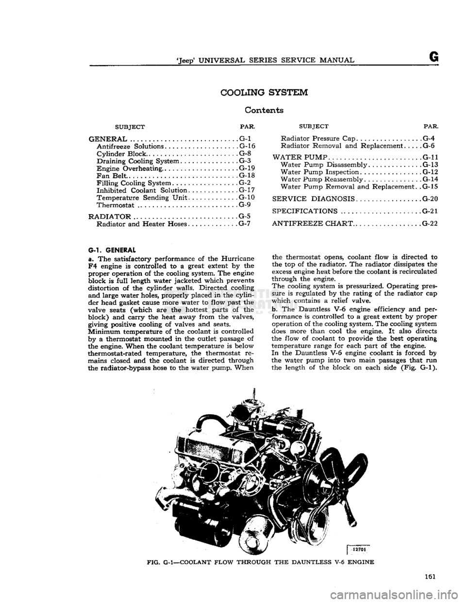
the water pump into two main passages that run the length of the block on each side (Fig. G-l).
FIG.
G-1—COOLANT
FLOW
THROUGH
THE
DAUNTLESS
V-6
ENGINE
161
Page 162 of 376
COOLING
SYSTEM
14263
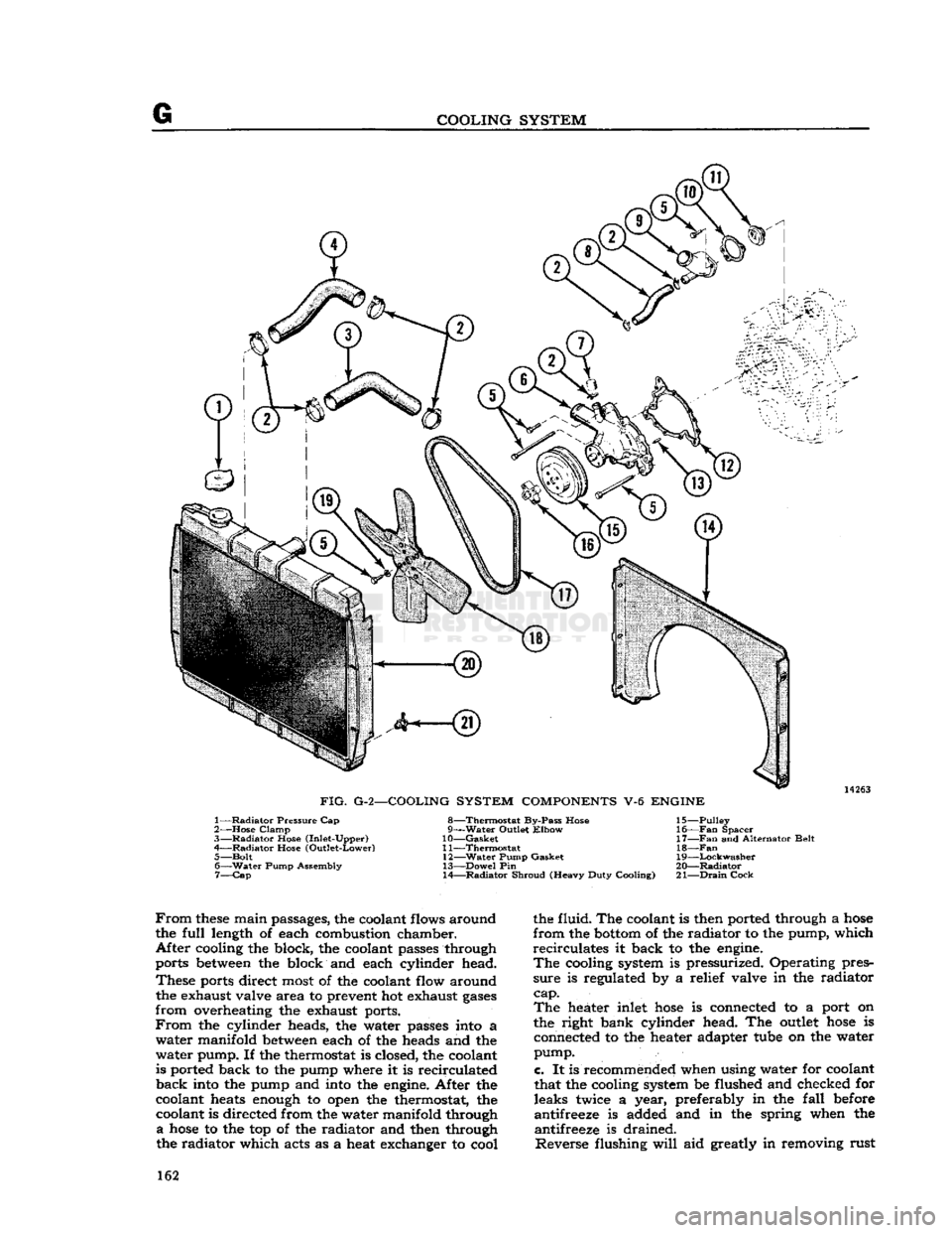
FIG.
G-2—COOLING SYSTEM
COMPONENTS
V-6
ENGINE
1—
Radiator
Pressure Cap
2—
Hose
Clamp
3—
Radiator
Hose (Inlet-Upper)
4—
Radiator
Hose (Outlet-Lower) 5—
Bolt
6—
Water
Pump Assembly 7—
Cap
8—Thermostat
By-Pass Hose
g—Water Outlet
Elbow
10—
Gasket
11—
Thermostat
12—
Water
Pump Gasket
13—
Dowel
Pin
14—
Radiator
Shroud (Heavy Duty Cooling) 15—
Pulley
16—
Fan
Spacer
17—
Fan
and Alternator Belt
18—Fan
19—
Lockwasher
20—
Radiator
21—
Drain
Cock
From
these
main passages, the coolant flows around
the
full
length of each combustion chamber.
After
cooling the block, the coolant passes through
ports between the block and each cylinder head.
These
ports direct most of the coolant flow around the exhaust valve area to prevent hot exhaust
gases
from
overheating the exhaust ports.
From
the cylinder heads, the water passes into a
water
manifold between each of the heads and the
water
pump. If the thermostat is closed, the coolant
is ported back to the pump where it is recirculated
back
into the pump and into the engine. After the
coolant heats enough to open the thermostat, the coolant is directed from the water manifold through
a
hose
to the top of the radiator and then through
the radiator which acts as a heat exchanger to cool the fluid. The coolant is then ported through a
hose
from
the bottom of the radiator to the pump, which
recirculates
it back to the engine.
The
cooling system is pressurized. Operating pres
sure
is regulated by a relief valve in the radiator
cap. The
heater inlet
hose
is connected to a port on
the right bank cylinder head. The outlet
hose
is connected to the heater adapter tube on the water
pump.
c.
It is recommended when using water for coolant
that the cooling system be flushed and checked for leaks twice a year, preferably in the
fall
before
antifreeze is added and in the spring when the antifreeze is drained.
Reverse
flushing
will
aid greatly in removing rust 162
Page 163 of 376

'Jeep*
UNIVERSAL
SERIES SERVICE
MANUAL
G and
scale, especially when used with a flushing
solution. A cleaning solution should be used to
loosen
the rust and scale before reverse flushing
the cooling system.
Flushing
is accomplished through the system in a direction
opposite
to the normal coolant flow.
This
action causes the water to get behind the corrosion
deposits
and force them out. To do this, remove
the upper and lower radiator
hoses.
Then
attach a
drain
hose
at the top of the radiator. Attach a new
piece of
hose
to the radiator
outlet
at the
bottom
and
insert the flushing gun. Connect the water
hose
to the flushing gun to a water
outlet
and the air
hose
to an air line.
Turn
on the water and when
the radiator is
full,
apply the air in short blasts,
allowing the radiator to
fill
between
blasts.
Con
tinue this flushing operation until the water runs
clear
through the top
hose.
With
the thermostat removed, attach a leadaway
hose
to the water
hose
inlet. Also attach a length
of new
hose
to the water
outlet
connection at the
top of the engine.
Turn
the water on and
fill
the
water jacket and then apply air in short blasts.
Continue
this flushing until the water runs clear.
Also
do the hot water heater. Remove heater water
outlet
hose
from heater core. Remove inlet from 163
Page 170 of 376
G
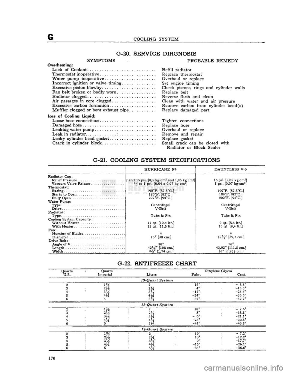
COOLING SYSTEM G-20.
SERVICE DIAGNOSIS
SYMPTOMS
PROBABLE REMEDY
Overheating:
Lack
of Coolant Refill radiator
Thermostat inoperative . Replace thermostat
Water
pump inoperative. Overhaul or replace
Incorrect
ignition or valve timing. Set
engine
timing
Excessive piston blowby Check pistons, rings and cylinder walls
Fan
belt
broken or badly worn Replace
belt
Radiator
clogged
Reverse flush and clean
Air
passages
in core
clogged
Clean with water and air pressure
Excessive carbon formation. Remove carbon from cylinder head(s) Muffler
clogged
or
bent
exhaust
pipe
Replace damaged part
Loss
of Cooling
Liquid:
Loose
hose
connections
Tighten
connections
Damaged
hose
Replace
hose
Leaking
water pump Overhaul or replace
Leak
in radiator Remove and repair
Leaky
cylinder head
gasket
Replace
gasket
Crack
in cylinder block. Small crack can be closed with
Radiator
or Block Sealer
G-21. COOLING SYSTEM SPECIFICATIONS
Radiator
Cap:
Relief
Pressure
Vacuum
Valve Release.
Thermostat:
Rating
Starts to Open
Fully
Open
Water
Pump:
Type.
Drive
Radiator:
Type
Cooling System Capacity: Without Heater
With
Heater..
Fan:
Number of Blades Diameter
Drive
Belt: Angle of V
Length
Width
HURRICANE
F4
7 and 15 psi. [0,5 kg-cm2 and 1,05 kg cm2]
lA to 1 psi. [0,04 a 0,07 kg-cm2]
190°F.
[87,8°C]
180°F.
[82°C]
202°F.
[94°C]
Centrifugal
V-Belt
Tube
8s Fin
11 qt. [10,4 ltr.] 12 qt. [11,5 ltr.]
15" [38 cm.]
38°
42%" [108 cm.] [1,74 cmJ
DAUNTLESS
V-6 15 psi. [1,05 kg-cm2]
1 psi. [0,07 kg-cm2]
190°F.
[87,8°C]
180°F.
[82°C]
202°F.
[94°C]
Centrifugal
V-Belt
Tube
& Fin
9 qt. [8.5 ltr.]
10 qt. [9,4 ltr.]
4
\SbA"
[39,7 cm.]
38°
43.92"
[111,5
cm.] Vg"
[0.952
cm.] G-22. ANTIFREEZE CHERT
Quarts
i
Quarts
Ethylene Glycol
U.S.
Imperial
Liters
Fahr.
Cent.
10-Quart
System
2
m
2
16°
-
8.8°
3
2V2
2%
4°
-15.5°
4
3H
-12°
-24.4°
5 4M -34°
-36.6°
6
5
5Vs
-62°
-52.2°
11-Quart
System
2 2
18° -
7.6°
3 2H
2%
8°
-13.3°
4
3%
-
6°
:
-21.10
5 4M 4M -23°
-30.5°
6
5
SVs
-47°
-43.8°
12-Quart
System
2
1 m 2 1
19° ;
- 7.2°
3
2*A
10°
!
-12.2°
4
I
3H
3M 0°
;
-17.7°
5 !
4M 4^ :
-15°
s
-26.1°
6 1 5
5%
-34°
-36.6°
170
Page 172 of 376
H
ELECTRICAL
SYSTEM SUBJECT
PAR.
Directional
Signal
Lamps
H-138
Hazard
Warning
Lamps
H-139
Head
Lamp
Replacement H-130
Head
Lamp
Aiming Procedure H-131 Headlight Dimmer Switch H-127
License
Plate
Lamp
H-136
Main
Light
Switch. H-126
Marker
Lights .H-l40
Parking
and
Turn
Signal
Light
H-133
Stop
Light
Switch. H-l28
Tail,
Stop and
Turn
Signal
Lamp
.H-134
H-1. GENERAL
All
'Jeep' Universal vehicles are equipped with 12- volt electrical systems. Use caution around the higher
voltage
of the 12-volt system as accidental
short
circuits are more capable of damaging electri
cal
units. Also, arcs around the 12-volt battery are
more apt to ignite any gas that may be escaping
from
it. In the following paragraphs
will
be found
information about the battery, distributor, coil,
generator, alternator,
voltage
regulator and start ing motor. These units with the connecting wires,
make
up the
engine
electrical system. The wiring
diagram
will
show the different circuits of the en
gine
electrical system and the various units which
make
up
those
circuits.
With
plastic-covered wiring harnesses use only
rubber-insulated
wiring clips.
Caution:
All current production vehicles are 12- volt, negative ground. Whenever servicing a 12-
volt electrical system, use caution, as an accidental
short
circuit is capable of damaging electrical units. Disconnect battery ground cable before changing
electrical
components.
H-2.
Battery
The
battery is a storage reservoir for electrical
energy produced by the alternator or generator.
The
battery should store sufficient energy for
operation of the entire electrical system when the
alternator
or generator is not pr 1,scing output,
such
as when the ignition is first turned on. Of
particular
importance is maintaining the electrolyte
at the correct level, regularly checking with a
hydrometer, and maintaining clean, tight cable connections.
Battery
service information is given in this section.
Caution:
Do not allow flames or sparks to be
brought near the vent
openings
of the battery since
hydrogen gas may be present in the battery and might explode.
Note:
The liquid in the battery (electrolyte) is a
solution of sulphuric acid which, on contact, can
injure
skin or
eyes,
or damage clothes. If it is spilled
on the skin or spattered in the
eyes,
promptly flush
it
away with quantities of clear water only. If the
acid
is spilled on clothes, wet it thoroughly with a
weak
solution of ammonia, or with a solution of sodium bicarbonate or baking soda.
SUBJECT
PAR.
HORN
H-137
ELECTRICAL
COMPONENT
REPLACEMENT
H-150
WINDSHIPLD
WIPER SYSTEM
H-141
thru
149
SERVICE
DIAGNOSIS.
. .H-151
ELECTRICAL
SPECIFICATIONS
H-152
Caution:
When installing the battery, the nega
tive terminal must be grounded. Reverse polarity of the battery can cause severe damage to the charging system.
Battery
Inspection
a.
Check
the specific gravity of the electrolyte in
each cell of the battery. A hydrometer reading of 1.260 indicates that the battery is fully charged.
If
the reading is 1.225 or below, the battery
needs
recharging.
If one or more cells is 25 "points" (.025) or more lower than the other cells, this in
dicates that the cell is shorted, the cell is about to
fail,
or there is a
crack
in the battery partition in
the case. Unless the battery is repaired or replaced, battery trouble
will
soon
be experienced.
b.
Check
the electrolyte level in each cell, add
distilled
water to maintain the solution [9,5 mm.] above the plates. Avoid overfilling. Replace
the filler caps and tighten securely. It is important to keep the electrolyte level above the plates at all
times because plates that are
exposed
for any
length of time
will
be seriously damaged.
c.
Check
the wing nuts on the hold-down frame for tightness. Tighten them only with finger pres
sure,
never with pliers or a wrench. Excessive
pressure
could damage the battery case.
d.
Clean
the battery terminals and cable con nectors. Prepare a strong solution of baking soda
and
water and brush it around the terminals to
remove any corrosion that is present. The cell caps must be tight and their vents sealed to prevent
cleaning solution entering the cells. After cleaning,
connect cables to battery and coat the terminals
with
heavy grease.
e.
Inspect the battery cables and replace if badly
corroded
or frayed.
Check
tightness
of terminal
screws to ensure
good
electrical connections.
Check
the
tightness
of the negative ground cable connection at the frame to ensure a
good
ground
connection.
f.
Load
test
the battery. Connect a voltmeter across the battery. Run the starting motor for 15 seconds. If the
voltage
does
not drop below 10
volts the battery is satisfactory. If the
voltage
falls
below the figure given, yet the specific gravity is
above
1.225,
the condition of the battery is questionable.
g. Be sure the
engine
ground strap connection, 172
Page 188 of 376
H
ELECTRICAL
SYSTEM
colder plug may be desirable. However, under- or
over-heating is usually caused by factors other than the type of
spark
plugs and the cause should be determined before changing plugs. The design of the
engine
calls for plugs equivalent to Champion
J-8
for F4
engines
and
A.C.
44S or
UJ12Y
Champ
ion for the V6 engines, (as installed in production)
though any factor that consistently affects
engine
operating temperature may cause this requirement
to change. Overheating may be caused by in sufficient tightening of the plug in the head, which interferes with the flow of heat away from the firing
tip.
If this is the case, the plug gasket
will
show very
little flattening. Over-tightening, in
turn,
will
pro duce too easy a heat flow path and result in cold
plug operation.
This
will
be evident by excessive
flattening
and
deformation of the gasket.
Prevailing
temperatures, condition of the cooling system, and
air-fuel
mixture can affect the
engine
operating temperature and should be taken into consideration.
H-34.
GENERATOR
— F4
ENGINE
The
generator is an air-cooled, two-brush unit
which
cannot be adjusted to increase or decrease output. For replacement,
voltage
regulator and generator must be matched for
voltage
and capa
city,
polarity, and common source of manufacture.
Otherwise,
either a
loss
of ampere capacity or a
burned
out generator
will
result. Generators for
these
vehicles are 12-volt. Par. H-l explains the 12-volt system. Refer to the specifications at the
end of this section for information on correct generator rating for a specific model series.
The
circuit
breaker,
voltage
regulator, and current-
limiting
regulator are built into one combination
unit.
Because the regulator and battery are part
of the generator
circuit,
the output of the generator
depends upon the
state
of charge and temperature
of the battery.
With
a discharged battery, the
output
will
be high, decreasing proportionally as the battery
becomes
charged. For service informa
tion covering current regulator see Par. H-41.
H-36.
Generator
Maintenance
A
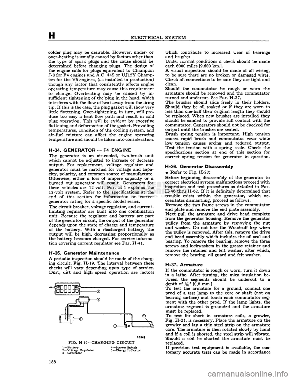
periodic inspection should be made of the charg
ing
circuit,
Fig. H-l9. The interval
between
these
checks
will
vary
depending upon type of service.
Dust,
dirt
and high speed operation are factors 10541
FIG.
H-19—CHARGING
CIRCUIT
1—
Battery
4-—Starter Switch
2—
Voltage
Regulator 5-—Charge Indicator
3—
Generator
which
contribute to increased wear of bearings
and
brushes.
Under
normal conditions a check should be made
each 6000 miles
[9.600
km.].
A
visual inspection should be made of all wiring,
to be sure there are no broken or damaged wires.
Check
all connections to be sure they are tight and
clean.
Should
the commutator be rough or worn the
armature
should be removed and the commutator
turned
and undercut. See Par. H-37.
The
brushes should slide freely in their holders.
Should
they be oil soaked or if they are worn to
less
than one-half their original length they should
be replaced. When new brushes are installed they should be sanded to provide
full
contact with the
commutator. Generators should not be checked for
output until the brushes are seated.
Brush
spring tension is important. High tension causes
rapid
brush and commutator wear while
low tension causes arcing and reduced output.
Test
the tension with a spring scale.
Check
the
specifications section at end of this section for
correct
spring tension for generator in question.
H-36.
Generator Disassembly
•
Refer to Fig. H-20:
Before beginning disassembly of the generator to
correct
electrical system malfunctions proceed with
inspection and
test
procedures as detailed in Par.
H-46
thru
H-62. If it is definitely determined that trouble exists within the generator, which necessitates dismantling, proceed as follows. Remove the two frame screws in the commutator
end plate and remove the end plate assembly. Next
pull
the armature and drive head complete
from
the generator housing. Remove the generator pulley from the armature by removing the nut
and
washer. Do not
lose
the Woodruff key when
the pulley is removed. After this, remove the drive
end head assembly which includes the oil seal and
bearing.
To remove the bearing, remove the three
screws and lockwashers in the grease retainer and remove the retainer and felt washer, after which,
remove the bearing, oil guard and felt washer.
H-37.
Armature
If
the commutator is rough or worn,
turn
it down
in
a lathe. After turning, the mica insulation be tween the
segments
should be undercut to a depth of 34* [0,8 mm.].
To
test
the armature for a ground, connect one
prod
of a
test
lamp to the core or shaft (not on
bearing
surface) and touch each commutator
seg
ment with the other prod. If the lamp lights, the
armature
segment
is grounded and the armature must be replaced.
To
test
for short in armature coils, a growler,
Fig.
H-21, is necessary. Place the armature on the growler and lay a thin steel strip on the armature
core.
The armature is then rotated slowly by hand
and
if a coil is shorted, the steel strip
will
vibrate.
Should
a coil be shorted the armature must be
replaced.
If
precision
test
equipment is available, the cus
tomary
accurate
tests
can be made in accordance 188