spark plugs JEEP CJ 1953 User Guide
[x] Cancel search | Manufacturer: JEEP, Model Year: 1953, Model line: CJ, Model: JEEP CJ 1953Pages: 376, PDF Size: 19.96 MB
Page 35 of 376
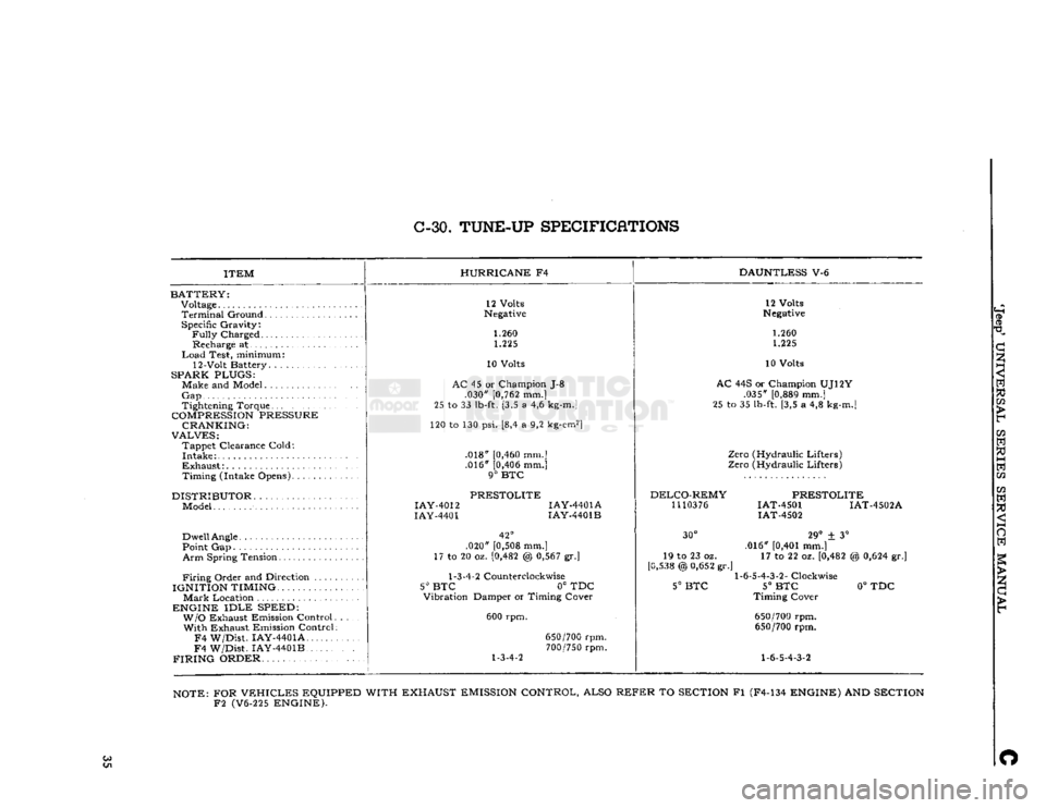
C-30.
TUNE-UP
SPECIFICATIONS
ITEM
BATTERY:
Voltage
Terminal
Ground Specific Gravity:
Fully
Charged Recharge at
Load
Test, minimum:
12-Volt Battery. .
SPARK PLUGS:
Make and Model
Gap
Tightening Torque
COMPRESSION
PRESSURE CRANKING:
VALVES:
Tappet Clearance Cold:
Intake
Exhaust:
Timing (Intake Opens)
DISTRIBUTOR
Model
Dwell
Angle
Point Gap
Arm
Spring Tension
Firing
Order and Direction ....
IGNITION TIMING.
Mark
Location
ENGINE
IDLE
SPEED: W/O
Exhaust Emission Control With Exhaust Emission Control
F4
W/Dist. IAY-4401A
F4
W/Dist. IAY-4401B
FIRING
ORDER HURRICANE
F4
DAUNTLESS
V-6
12 Volts
Negative
1.260 1.225
10 Volts
AC
45 or Champion J-8 .030"
[0,762
mm.]
25 to 33
lb-ft.
[3,5 a 4,6
kg-m.]
120 to 130 psi. [8,4 a 9,2
kg-cm2]
.018"
[0,460
mm.] .016"
[0,406
mm.]
9°
BTC
PRESTOLITE
IAY-4012
IAY-4401A
IAY-4401
IAY-4401B
42°
.020"
[0,508
mm.]
17 to 20 oz.
[0,482
@
0,567
gr.]
1-3-4-2
Counterclockwise
5° BTC
0° TDC
Vibration Damper or Timing Cover
600 rpm.
1-3-4-2
650/700
rpm.
700/750
rpm. 12 Volts
Negative
1.260 1.225
10 Volts
AC
44S or Champion UJ12Y .035"
[0,889
mm.]
25 to 35
lb-ft.
[3,5 a 4,8
kg-m.]
Zero (Hydraulic Lifters)
Zero (Hydraulic Lifters)
DELCO-REMY
1110376
PRESTOLITE
IAT-4501 IAT-4502A
IAT-4502
30°
19 to 23 oz.
[0,538
@
0,652
gr.'
5°
BTC
29°
± 3°
.016"
[0,401
mm.] 17 to 22 oz.
[0,482
1-6-5-4-3-2-
Clockwise
5°
BTC
Timing Cover
650/700
rpm.
650/700
rpm.
1-6-5-4-3-2
%
0,624
gr.]
0°
TDC
NOTE:
FOR
VEHICLES
EQUIPPED WITH EXHAUST
EMISSION
CONTROL, ALSO
REFER
TO
SECTION
Fl (F4-134
ENGINE)
AND
SECTION
F2
(V6-225
ENGINE).
Co O
Page 37 of 376
'Jeep9
UNIVERSAL SERIES SERVICE
MANUAL
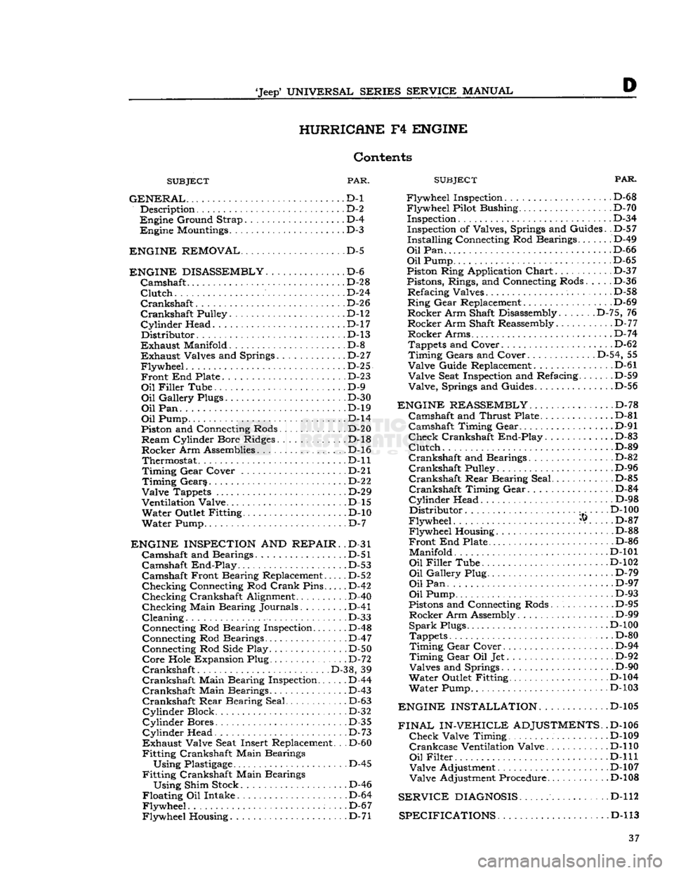
D HURRICANE
F4
ENGINE
Contents
SUBJECT
PAR.
GENERAL...
D-l Description D-2
Engine
Ground Strap D-4
Engine
Mountings D-3
ENGINE REMOVAL
D-5
ENGINE DISASSEMBLY
D-6
Camshaft
.......
D-28
Clutch
D-24
Crankshaft.
D-26
Crankshaft
Pulley. D-l2
Cylinder
Head. .D-17
Distributor.
.D-13
Exhaust
Manifold D-8
Exhaust
Valves and Springs D-2
7
Flywheel.
. D-25
Front
End Plate D-23
Oil
Filler
Tube D-9
Oil
Gallery Plugs D-30
Oil
Pan. . ...D-19
Oil
Pump D-l4
Piston and Connecting Rods. . . D-20
Ream
Cylinder Bore Ridges. D-l8
Rocker
Arm Assemblies D-l6 Thermostat D-ll
Timing
Gear
Cover . . D-21
Timing
Gears D-22
Valve
Tappets D-29
Ventilation Valve D-l5
Water
Outlet Fitting D-10
Water
Pump D-7
ENGINE INSPECTION
AND
REPAIR.
.D-31
Camshaft
and Bearings. D-51
Camshaft
End-Play
. . .D-53
Camshaft
Front Bearing Replacement..... D-52
Checking
Connecting Rod
Crank
Pins D-42
Checking
Crankshaft Alignment .
.
D-40
Checking
Main Bearing Journals. D-41
Cleaning.
. D-33 Connecting Rod Bearing Inspection D-48
Connecting Rod Bearings D-47 Connecting Rod Side Play D-50
Core
Hole Expansion Plug D-72
Crankshaft
.
.
D-38, 39
Crankshaft
Main Bearing Inspection D-44
Crankshaft
Main Bearings D-43
Crankshaft
Rear
Bearing Seal D-63
Cylinder
Block D-32
Cylinder
Bores D-35
Cylinder
Head. . . D-73
Exhaust
Valve Seat Insert Replacement. .
.
D-60
Fitting
Crankshaft Main Bearings
Using
Plastigage
D-45
Fitting
Crankshaft Main Bearings
Using
Shim Stock D-46
Floating
Oil Intake D-64
Flywheel.
. . .D-67
Flywheel
Housing D-71
SUBJECT
FAR.
Flywheel
Inspection. D-6 8
Flywheel
Pilot Bushing D-70 Inspection D-3 4
Inspection of Valves, Springs and Guides. .D-57
Installing
Connecting Rod Bearings....... D-49
Oil
Pan D-66
Oil
Pump D-65
Piston Ring Application
Chart
D-3 7
Pistons, Rings, and Connecting Rods..... D-36
Refacing
Valves
.
D-58
Ring
Gear
Replacement D-69
Rocker
Arm Shaft Disassembly. D-75, 76
Rocker
Arm Shaft Reassembly.
.
D-77
Rocker
Arms D-74
Tappets and Cover. . D-62
Timing
Gears and Cover D-54, 55
Valve
Guide Replacement D-61
Valve
Seat Inspection and Refacing D-59
Valve,
Springs and Guides D-56
ENGINE REASSEMBLY
D-78
Camshaft
and
Thrust
Plate .D-81
Camshaft
Timing
Gear
D-91
Check
Crankshaft
End-Play.
............D-83
Clutch.
...D-89
Crankshaft
and Bearings................ D-82
Crankshaft
Pulley D-96
Crankshaft
Rear
Bearing Seal.. .
.
D-85
Crankshaft
Timing
Gear
D-84
Cylinder
Head D-98
Distributor
D-l
00
Flywheel
®. . .. D-87
Flywheel
Housing D-88
Front
End Plate D-86
Manifold.......
D-101
Oil
Filler
Tube D-102
Oil
Gallery Plug. D-79
Oil
Pan. D-97
Oil
Pump D-93
Pistons and Connecting Rods D-95
Rocker
Arm Assembly D-99
Spark
Plugs. .D-100
Tappets D-80
Timing
Gear
Cover D-94
Timing
Gear
Oil Jet D-92
Valves
and Springs ... D-90
Water
Outlet Fitting D-104
Water
Pump D-103
ENGINE INSTALLATION.
............D-105
FINAL IN-VEHICLE
ADJUSTMENTS.
.D-106
Check
Valve Timing . . D-109
Crankcase
Ventilation Valve. D-l 10
Oil
Filter
, . .
...D-lll
Valve
Adjustment D-107
Valve
Adjustment Procedure D-l08
SERVICE
DIAGNOSIS
D-112
SPECIFICATIONS D-l
13 37
Page 38 of 376
HURRICANE
F4
ENGINE
D-1.
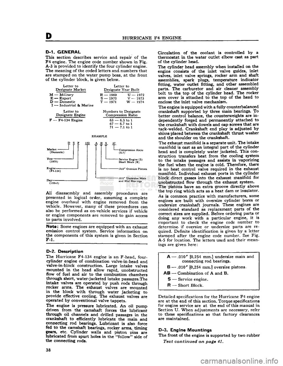
GENERAL
This
section describes service and repair of the
F4
engine. The
engine
code
number shown in Fig.
A-3
is provided to identify the four cylinder engine.
The
meaning of the coded letters and numbers that
are
stamped on the water pump boss, at the front of the cylinder block, is given below.
Letter
to
Designate
Market
M
—
Military
E
—
Export
D
— Domestic
I
—
Industrial
&
Marine
Letter
to
Designate
Engine
Letter
to
Designate
Year
Built
R
— 1969
S
— 1970
T
— 1971
U—
1972
V
— 1973
W
— 1974
Numbers
to Designate
Compression
Ratio
F
— F4-134
Engine
63
67
•
71
-
6.3 to 1
•
6.7 to 1
-
7.1 to 1
Market
-
D
S F
(Domestic)
(1970)
Engine-
EXAMPLE
123 A B S
(F4-134)
Day- "L
Compression
Ratio
(6.7)
-
Service Engine (S)
Short
Block
(R)
-.010*
Oversize Pistons
(123rd)
-.010*
Undersize
Main
and
Rod Bearings
All
disassembly and assembly procedures are
presented in logical order, assuming a complete
engine
overhaul with
engine
removed from the vehicle. However, many of
these
procedures can
also be performed as on-vehicle services if vehicle
or
engine
components are removed to gain access
to parts involved.
Note:
Some
engines
are equipped with an exhaust
emission control system. Service information on
the components of this system is given in Section
F-l.
D-2.
Description
The
Hurricane
F4-134
engine
is an F-head, four-
cyiinder
engine
of combination valve-in-head and valve-in-block construction.
Large
intake valves
mounted in the head allow
rapid,
unobstructed
flow of fuel and air to the combustion chambers through short, water-jacketed intake passages.The
intake valves are operated by push rods through
rocker
arms. The exhaust valves are mounted
in
the block with through water jacketing to provide
effective
cooling. The exhaust valves are
operated by conventional valve tappets.
The
engine
is pressure lubricated. An oil pump
driven
from the camshaft forces the lubricant
through oil channels and drilled passages in the
crankshaft
to efficiently lubricate the main and
connecting rod bearings.
Lubricant
is also force
fed to the camshaft bearings, rocker arms, timing
gears, etc.
Cylinder
walls and piston pins are
lubricated
from spurt
holes
in the "follow" side of
the connecting rods.
Circulation
of the coolant is controlled by a
thermostat in the water
outlet
elbow cast as part
of the cylinder head.
The
cylinder head assembly when installed on the
engine
consists of the inlet valve guides, inlet valves, inlet valve springs, rocker arm and shaft assemblies, spark plugs, temperature indicator
fitting, water
outlet
fitting, and other assembled
parts.
The carburetor and air cleaner assembly
bolt to the top of the cylinder head. The rocker
arm
cover is attached to the top of the head to
enclose
the inlet valve mechanism.
The
engine
is equipped with a fully counterbalanced
crankshaft
supported by three main bearings. To better control balance, the counterweights are in
dependently forged and permanently attached to
the crankshaft with dowels and cap screws that are tack-welded.
Crankshaft
end play is adjusted by
shims placed
between
the crankshaft thrust washer
and
the shoulder on the crankshaft.
The
exhaust manifold is a separate unit. The intake
manifold is cast as an integral part of the cylinder
head and is completely water jacketed.
This
con
struction transfers heat from the cooling system
to the intake passages and assists in vaporizing
the fuel when the
engine
is cold. Therefore, there
is no heat control valve required in the exhaust manifold. Individual exhaust ports in the cylinder
block direct
gasses
into the exhaust manifold for unobstructed flow through the exhaust system.
The
pistons have an extra
groove
directly above
the top ring which acts as a heat dam or insulator.
As
is common practice with manufacturers,
some
engines
are built with oversize cylinder bores or undersize crankshaft journals. These
engines
are
considered standard as replacement parts of the
correct
sizes are supplied. Before ordering parts or
doing any work with a particular engine, it is important to check the
engine
code
number to
determine if oversize or undersize parts are re
quired.
Definite identification is given by a letter
stamped after the
engine
code
number. See Fig.
A-5
for location. The letters used and their mean ings are given here:
A
— .010*
[0,254
mm.] undersize main and
connecting rod bearings.
B
— .010"
[0,254
mm.] oversize pistons.
AB
—
Combination
of A and B.
S
—
Service
engine.
R
—
Short
Block.
Detailed specifications for the
Hurricane
F4
engine
are
at the end of this section.
Torque
specifications
for
engine
service are at the end of this manual in Section U. When adjustments are necessary, refer to
these
specifications so that factory clearances
are
maintained.
D-3.
Engine Mountings
The
front of the
engine
is supported by two rubber
Text continued on
page
41. 38
Page 41 of 376
'Jeep*
UNIVERSAL SERIES
SERVICE
MANUAL
D
insulator
mountings attached to the frame side
rail
brackets. The
rear
of the engine-transmission
assembly is supported by a rubber insulator
mounting under the
rear
of the transmission on
the frame center cross member.
This
cross member
is bolted to the frame side
rails
so that it can be
dropped when removing the transmission or engine-
transmission
assembly. The rubber insulators allow
free side and vertical oscillation to effectively
neutralize
engine
vibration at the source.
The
rubber
insulator mountings should be inspected
for separation and deterioration by jacking the
power plant away from the frame, near the sup
ports. Vibration cannot be effectively absorbed by
separated or worn insulators. They should be re placed if faulty.
D-4.
Engine
Ground
Strap
To
be sure of an
effective
ground for the electrical
circuits,
a ground strap bridges the right front
engine
support to the chassis. The connections of this strap must be kept clean and tight for proper
operation of the electrical system.
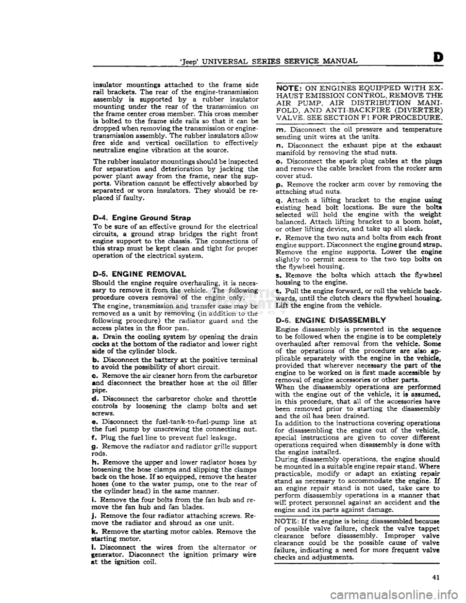
D-5. ENGINE REMOVAL
Should
the
engine
require overhauling, it is neces
sary
to remove it from the vehicle. The following procedure covers removal of the
engine
only.
The
engine, transmission and transfer case may be
removed as a unit by removing (in addition to the following procedure) the radiator guard and the
access plates in the floor pan.
a.
Drain
the cooling system by opening the
drain
cocks at the
bottom
of the radiator and lower right
side of the cylinder block.
b.
Disconnect the battery at the positive terminal
to avoid the possibility of short
circuit.
c. Remove the air cleaner horn from the carburetor
and
disconnect the breather
hose
at the oil filler
pipe.
d.
Disconnect the carburetor choke and throttle controls by loosening the clamp
bolts
and set
screws.
e. Disconnect the fuel-tank-to-fuel-pump line at the fuel pump by unscrewing the connecting nut.
f- Plug the fuel line to prevent fuel leakage.
g. Remove the radiator and radiator grille support
rods.
h. Remove the upper and lower radiator
hoses
by
loosening the
hose
clamps and slipping the clamps
back
on the
hose.
If so equipped, remove the heater
hoses
(one to the water pump, one to the
rear
of
the cylinder head) in the same manner.
i.
Remove the four
bolts
from the fan hub and re
move
the fan hub and fan blades.
j.
Remove the four radiator attaching screws. Re
move
the radiator and shroud as one unit, k. Remove the starting motor cables. Remove the
starting
motor.
I.
Disconnect the wires from the alternator or
generator. Disconnect the ignition
primary
wire
at the ignition coil.
NOTE:
ON
ENGINES EQUIPPED WITH EX
HAUST
EMISSION CONTROL, REMOVE THE
AIR
PUMP,
AIR
DISTRIBUTION
MANI
FOLD,
AND
ANTI-BACKFIRE (DIVERTER)
VALVE.
SEE SECTION
Fl
FOR PROCEDURE.
m.
Disconnect the oil pressure and temperature
sending unit wires at the units.
n.
Disconnect the exhaust pipe at the exhaust
manifold by removing the stud nuts.
o.
Disconnect the
spark
plug cables at the plugs
and
remove the cable bracket from the rocker arm cover stud.
p.
Remove the rocker arm cover by removing the
attaching stud nuts.
q.
Attach a lifting bracket to the
engine
using
existing head bolt locations. Be sure the
bolts
selected
will
hold the
engine
with the weight
balanced.
Attach lifting bracket to a boom hoist,
or
other lifting device, and take up all slack,
r.
Remove the two nuts and
bolts
from each front
engine
support. Disconnect the
engine
ground strap.
Remove the
engine
supports.
Lower
the
engine
slightly to permit access to the two top
bolts
on
the flywheel housing.
s. Remove the
bolts
which attach the flywheel
housing to the engine.
t.
Pull
the
engine
forward, or
roll
the vehicle back
wards,
until the clutch clears the flywheel housing.
Lift
the
engine
from the vehicle.
D-6. ENGINE DISASSEMBLY
Engine
disassembly is presented in the sequence to be followed when the
engine
is to be completely
overhauled after removal from the vehicle. Some
of the operations of the procedure are also ap
plicable
separately with the
engine
in the vehicle,
provided
that wherever necessary the part of the
engine
to be worked on is first made accessible by
removal
of
engine
accessories or other parts.
When
the disassembly operations are performed
with
the
engine
out of the vehicle, it is assumed,
in
this procedure, that all of the accessories have been removed
prior
to starting the disassembly
and
the oil has been drained.
In
addition to the instructions covering operations
for disassembling the
engine
out of the vehicle,
special
instructions are given to cover different
operations required when disassembly is
done
with the
engine
installed.
During
disassembly operations, the
engine
should
be mounted in a suitable
engine
repair
stand. Where
practicable,
modify or adapt an existing repair
stand
as necessary to accommodate the engine. If
an
engine
repair stand is not used, take care to
perform
disassembly operations in a manner that
will
protect personnel against an accident and the
engine
and its parts against damage.
NOTE:
If the
engine
is being disassembled because
of possible valve failure, check the valve tappet
clearance
before disassembly. Improper valve
clearance
could be the possible cause of valve
failure,
indicating a need for more frequent valve
checks and adjustments. 41
Page 55 of 376
'Jeep'
UNIVERSAL
SERIES SERVICE
MANUAL
develop
into surface cracks and cause failure.
Measure
the over all free length of the springs and
replace any that do not measure to standard: 1%" [35,7 mm.] for intake valve springs and 2j^"
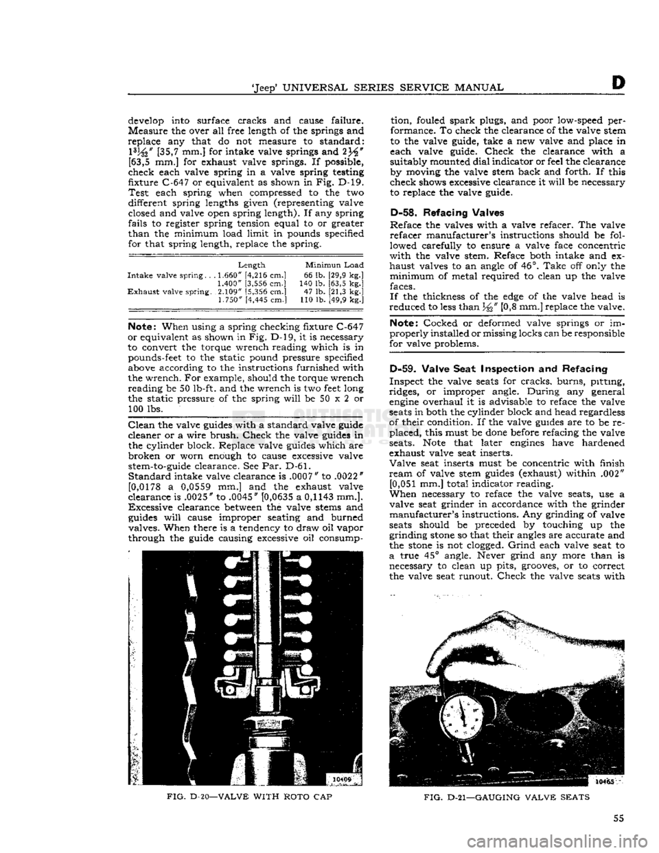
[63,5 mm.] for exhaust valve springs. If possible,
check each valve spring in a valve spring testing
fixture C-647 or equivalent as shown in Fig. D-l9.
Test
each spring when compressed to the two
different spring lengths given (representing valve closed and valve open spring length). If any spring
fails to register spring tension equal to or greater
than
the minimum load limit in pounds specified for that spring length, replace the spring.
Length
Minimun
Load
Intake
valve spring. . .
1.660"
[4,216 cm.] 66 lb. [29,9 kg.]
1.400"
[3,556 cm.] 140 lb. [63,5 kg.]
Exhaust
valve spring. 2.109" [5,356 cm.] 47 lb. [21,3 kg.]
1.750"
[4,445 cm.] 110 lb. [49,9 kg.]
Note:
When using a spring checking fixture C-647
or
equivalent as shown in Fig. D-l9, it is necessary
to convert the torque wrench reading which is in pounds-feet to the static pound pressure specified above according to the instructions furnished with
the wrench. For example, should the torque wrench reading be 50 lb-ft. and the wrench is two
feet
long
the static pressure of the spring
will
be 50 x 2 or 100 lbs.
Clean
the valve
guides
with a standard valve guide
cleaner or a wire
brush.
Check
the valve
guides
in the cylinder block. Replace valve
guides
which are
broken
or worn enough to cause excessive valve
stem-to-guide
clearance. See Par. D-61.
Standard
intake valve clearance is .0007" to .0022"
[0,0178
a
0,0559
mm.] and the exhaust valve
clearance is .0025" to .0045" [0,0635 a
0,1143
mm.].
Excessive
clearance
between
the valve
stems
and
guides
will
cause improper seating and burned
valves. When there is a tendency to draw oil vapor
through the guide causing excessive oil consump tion, fouled
spark
plugs, and poor low-speed per
formance. To check the clearance of the valve stem
to the valve guide, take a new valve and place in
each valve guide.
Check
the clearance with a
suitably mounted
dial
indicator or feel the clearance by moving the valve stem back and forth. If this
check shows excessive clearance it
will
be necessary to replace the valve guide.
D-58.
Refacing Valves
Re
face the valves with a valve refacer. The valve
refacer
manufacturer's instructions should be fol
lowed carefully to ensure a valve face concentric
with
the valve stem. Reface both intake and ex
haust valves to an angle of 46°.
Take
off only the
minimum
of metal required to clean up the valve faces.
If
the thickness of the
edge
of the valve head is
reduced to
less
than
J^>"
[0>8 mm.] replace the valve.
Note:
Cocked or deformed valve springs or im
properly
installed or missing locks can be responsible
for valve problems.
D-59.
Valve Seat Inspection
and
Refacing
Inspect the valve
seats
for
cracks,
burns, pitting,
ridges, or improper angle.
During
any general
engine
overhaul it is advisable to reface the valve
seats
in both the cylinder block and head regardless
of their condition. If the valve
guides
are to be re placed, this must be
done
before refacing the valve
seats.
Note
that later
engines
have hardened
exhaust valve seat inserts.
Valve
seat inserts must be concentric with finish
ream
of valve stem
guides
(exhaust) within .002"
[0,051
mm.] total indicator reading.
When
necessary to reface the valve seats, use a
valve seat grinder in accordance with the grinder
manufacturer's
instructions. Any grinding of valve
seats
should be preceded by touching up the
grinding
stone
so that their angles are accurate and
the
stone
is not
clogged.
Grind
each valve seat to
a
true 45° angle. Never grind any more than is necessary to clean up pits, grooves, or to correct
the valve seat runout.
Check
the valve
seats
with
10465
FIG.
D-20—VALVE
WITH
ROTO
CAP
FIG.
D-21—GAUGING
VALVE
SEATS
55
Page 62 of 376
D
HURRICANE
F4
ENGINE d.
Remove the intake valve adjusting screw lock-
nuts from each of the rocker arm valve lash ad
justing
screws. Remove the screws from the rocker
arms.
D-76.
Inspection and
Repair
Run
a round wire brush through the bore of the
rocker
arm shaft and clean out the drilled oil holes.
Clean
out the oil
holes
in the rocker arm shaft
brackets,
and the oil
holes
and
grooves
in the bores
of the rocker arm.
Inspect
the diameter of the shaft at the rocker arm
bearing
areas. Replace the shaft if there are scores
or
abrasion marks along the length of the shaft.
Check
the shaft for alignment by rolling it across
a
smooth level surface. If the shaft
will
not
roll
freely, or if it rolls with a bumping motion, the
shaft is out of alignment and must be replaced.
Inspect
the threads of the adjusting screw
hole
in
the rocker arms and if necessary clean with a
proper
size tap. Replace the adjusting screw lock-
nut or the adjusting screw if either part is damaged
or
deformed.
Inspect
the threads in the tapped
hole
in the top
of the rocker arm shaft brackets and if necessary
clean
with a proper size tap. Replace the bracket
if
either side is worn or scored.
D-77.
Reassembly
a.
Install
two rocker arm shaft plugs, one in each
end of the shaft. Slide two
rocker
arm
shaft brackets
onto
the center of the shaft. Align the tapped
holes
in
the brackets with the drilled
holes
in the top of
the shaft and install the rocker arm shaft lock
screws,
making sure the points of the screws enter
the drilled
holes
in the shaft.
b.
Screw the intake valve adjusting screws into
the rocker arms and install the locknuts.
c.
The rocker arms are paired; that is, two of the
arms
are angled to the right and two are angled to
the left. One of each type is used on each end of
the rocker arm shaft. Slide a rocker arm with the
adjusting
screw end of the rocker arm angling
away
from the bracket
onto
the shaft so that the
adjusting
screw is on the same side of the shaft
as the mounting
hole
in the bracket.
d.
Temporarily
secure the end bracket in place by
installing
a rocker arm cover stud in the tapped
opening in the top of the support.
e. Assemble the parts on the
opposite
end of the
rocker
arm shaft repeating
steps
c and d above.
D-78. ENGINE REASSEMBLY
The
engine
reassembly procedure in the following
paragraphs
is given in the sequence to be followed
when the
engine
is being completely overhauled.
Individual
inspection,
repair,
and fitting operations
previously covered in detail are made throughout
the reassembly procedure. The reassembly pro
cedure
does
not cover accessories. If a new cylinder
block
fitted with pistons is used, many of the
operations
will
not be required.
Mount
the cylinder block in an
engine
repair stand.
If
an
engine
stand is not available, perform the fol
lowing reassembly operation in a manner designed to protect personnel against an accident and the
engine
and its parts against damage.
Note:
During
engine
reassembly, use Perfect Seal
Aerosol
Spray
Sealer
Part
No.
994757
on all
engine
gaskets to ensure against vacuum, oil, gasoline and
water
leaks. Apply to head gaskets, valve covers,
water
pumps, oil pan gaskets, radiator and heater
hose
connections, felt gaskets, gasoline and oil line
connections, stud bolts,
spark
plug threads, and
grease retainer washers. Refer to manufacturer's in
structions on container for proper application pro
cedure.
D-79.
Install
Oil
Gallery
Plug
Coat
plug threads with a suitable sealing compound
and
install the plugs in the front and
rear
ends of
the oil gallery in the cylinder block and the
rear
end of the cylinder head. Torque the plugs 20 to 25 lb-ft. [2,8 a 3,4 kg-m.].
There
is also a pipe plug
(}/g,f
[3,2 mm.] slotted, headless) in the opening in the main oil gallery inside the cylinder block at No. 2 cylinder and another pipe plug
(}/g
"
square-head) in the opening
in
the oil passage directly below the oil pump intake
passage. If
these
two pipe plugs were removed,
make
certain they are reinstalled in the locations
described above or the counterweight of the
crankshaft
might strike the projecting head of the
square-head
plug.
D-80.
Install
Tappets
Turn
the block upside down. Beginning at the
rear
end of the cylinder block, install the intake
and
exhaust valve tappets in the tappet bores in the cylinder block in the following order: one
exhaust, two intake, two exhaust, two intake, and
finally
one exhaust valve tappet.
Check
the tappet to bore fit of each tappet as it
is installed in the block. If the stem-to-block
clearance
tolerance of .0005" to .002" [0,0127 a
0,051 mm.] is
exceeded
install a new tappet fitting
within
this tolerance or ream the bore to accomo date the next oversize tappet which is available
in
.004" oversize.
D-81.
Install
Camshaft and
Thrust
Plate
Lubricate
all camshaft bearings and cam surfaces generously with clean, light
engine
oil.
Carefully,
so not to damage or score the camshaft front bear
ing,
install the camshaft, locating it properly in the bearings. Do not allow the
rear
end of the camshaft to strike sharply against the expansion plug
installed
in the
rear
end of the bore.
Install
the camshaft thrust plate. Slide the thrust
plate spacer
onto
the end of the camshaft with the
beveled inner
edge
of the spacer facing the cam
shaft. If the same camshaft is being reinstalled,
install
any shims previously removed. These shims
are
placed
between
the camshaft shoulder and the
spacer.
Torque the thrust plate attaching
bolts
20
to 26 lb-ft. [2,8 a 3,6 kg-m.].
End
play of the camshaft is determined by running
clearance
between
the
rear
face of the camshaft
gear and the thrust plate. The standard clearance 62
Page 67 of 376
'Jeep'
UNIVERSAL
SERIES SERVICE
MANUAL
D
Lubricate
the connecting rod bearing surfaces
generously with
engine
oil and install the bearing
cap with the numbered side matched to the num
bered side of the connecting rod. Torque the nuts
evenly 35 to 45 lb-ft. [4,8 a 6,2 kg-m.]. The con
necting rod cap nuts are locked with stamped nuts.
Used
stamped nuts should be discarded and re
placed with new
ones.
These locking stamped nuts
should be installed with the flat face toward the
connecting rod nut.
Turn
the locking nut finger
tight and then 34
turn
more with a wrench. Refer
to Par. D-36 for detailed information on fitting pistons and rings in the cylinder bores.
D-96.
Install
Crankshaft
Pulley
Align
the keyway in the pulley with the woodruff key installed in the crankshaft. Drive the pulley
onto
the crankshaft and secure it in place with
the crankshaft pulley nut. Insert a block of wood
between
one of the counterweights on the
crank
shaft and the side of the cylinder block to prevent the crankshaft from turning, then tighten the nut.
D-97.
Install
Oil Pan
Before installing the oil pan, make a final internal
inspection particularly making certain that the
inside of the cylinder block is clean. Apply a thin
coat of gasket paste on the oil pan. Place the new
oil
pan gasket in position. Set the oil pan in posi
tion on the cylinder block and install the oil pan.
Torque
the attaching
bolts
12 to 15 lb-ft. [1,7 a 2,1
kg-m.].
Install
the oil pan
drain
plug and gasket
and
tighten the plug securely.
D-98.
Install
Cylinder
Head
Make
certain that the entire top of the cylinder
block
assembly, the lower surface of the cylinder
head,
and the cylinder head gasket are clean. Blow
all
dirt
or carbon out of the blind tapped bolt
holes
in
the cylinder block before the cylinder head and gasket are installed. Using aerosol spray sealer
Part
No. 994757, spray a thincoat on both surfaces
of the head gasket, position the new cylinder head gasket with the crimped
edges
of the gasket metal down (See Fig. D-31).
This
gasket position allows a
positive seal along the narrow surfaces of the
cylin
der
head
between
the combustion chambers and
eliminates the possibility of burning combustion
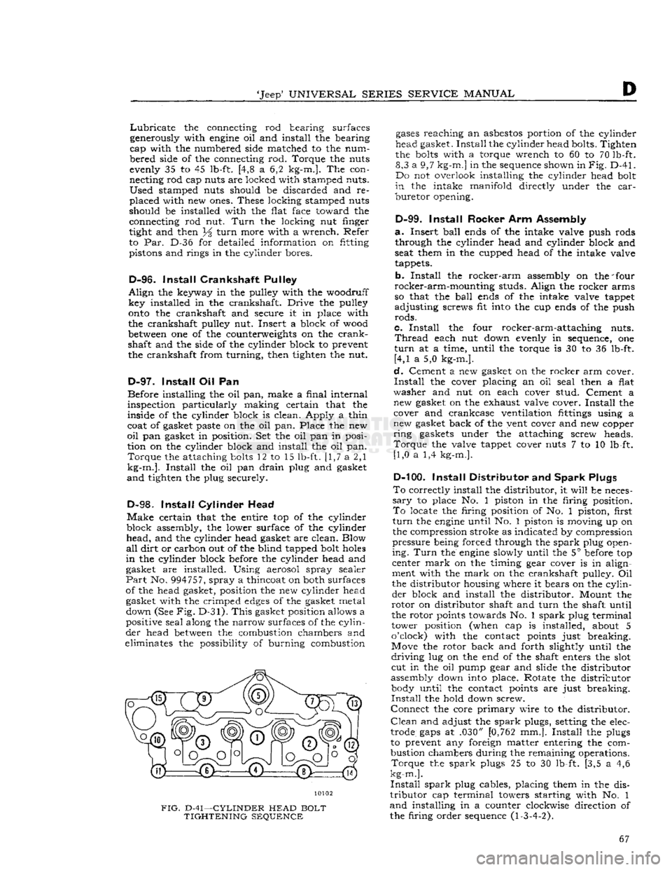
10102
FIG.
D-41—CYLINDER
HEAD
BOLT
TIGHTENING
SEQUENCE
gases
reaching
an
asbestos
portion of the cylinder
head gasket.
Install
the cylinder head bolts. Tighten
the
bolts
with a torque wrench to 60 to 70 lb-ft. 8,3 a 9,7
kg-m.]
in the sequence shown in
Fig.
D-41.
Do not overlook installing the cylinder head bolt
in
the intake
manifold
directly under the
car
buretor
opening.
D-99.
Install
Rocker Arm Assembly
a.
Insert
ball
ends of the intake valve push rods through the cylinder head and cylinder block and
seat them in the cupped head of the intake valve
tappets.
b.
Install
the
rocker-arm
assembly on the 'four
rocker-arm-mounting
studs. Align the rocker arms
so that the
ball
ends of the intake valve tappet
adjusting
screws fit into the cup ends of the push
rods.
c.
Install
the four rocker-arm-attaching nuts.
Thread
each nut down evenly in sequence, one
turn
at a time, until the torque is 30 to 36 lb-ft. [4,1 a 5,0 kg-m.].
d.
Cement a new gasket on the rocker arm cover.
Install
the cover placing an oil seal then a flat
washer
and nut on each cover stud. Cement a new gasket on the exhaust valve cover.
Install
the cover and crankcase ventilation fittings using a
new gasket back of the vent cover and new copper
ring
gaskets under the attaching screw heads.
Torque
the valve tappet cover nuts 7 to 10 lb-ft. [1,0 a 1,4 kg-m.].
D-100.
Install
Distributor and
Spark
Plugs
To
correctly install the distributor, it
will
be neces
sary
to place No. 1 piston in the firing position.
To
locate the firing position of No. 1 piston, first
turn
the
engine
until No. 1 piston is moving up on
the compression stroke as indicated by compression
pressure
being forced through the
spark
plug open
ing.
Turn
the
engine
slowly until the 5° before top
center
mark
on the timing gear cover is in align
ment with the
mark
on the crankshaft pulley. Oil
the distributor housing where it bears on the
cylin
der
block and install the distributor. Mount the
rotor
on distributor shaft and
turn
the shaft until
the rotor points towards No. 1
spark
plug terminal
tower position (when cap is installed, about 5
o'clock) with the contact points just breaking.
Move the rotor back and forth slightly until the
driving
lug on the end of the shaft enters the slot cut in the oil pump gear and slide the distributor
assembly down into place. Rotate the distributor body until the contact points are just breaking.
Install
the hold down screw.
Connect
the core
primary
wire to the distributor.
Clean
and adjust the
spark
plugs, setting the elec
trode
gaps
at .030" [0,762 mm.].
Install
the plugs
to prevent any foreign matter entering the com
bustion chambers during the remaining operations.
Torque
the
spark
plugs 25 to 30 lb-ft. [3,5 a 4,6
kg-m.].
Install
spark
plug cables, placing them in the dis
tributor
cap terminal towers starting with No. 1
and
installing in a counter clockwise direction of
the firing order sequence (1-3-4-2). 67
Page 68 of 376
D
HURRICANE
F4
ENGINE
D-101.
Install
Manifold
If
manifold studs were removed for replacement,
apply sealer on the stud threads
before
installing
a
new stud.
See Section Fl for exhaust emission controlled
engines.
Make
certain that no foreign objects are inside the manifold and that all
passages
are clear. Place a
new set of manifold
gaskets
in position on the side
of the cylinder block.
Then,
carefully slide the manifold
onto
the studs and against the cylinder block being careful not to damage the gaskets.
Torque
all manifold attaching nuts evenly 29 to
35 lb-ft. [4,0 a 4,8 kg-m.].
D-102.
Install
Oil
Filler
Tube
When
installing the oil filler tube, be sure that the
beveled lower end is away from the crankshaft.
Place a
piece
of
hard
wood
over the top of the
tube
to prevent damage to the cap gasket seat.
D-103.
Install
Water Pump
Make
certain that the mating surfaces of the water pump and the cylinder block are clean and smooth.
Install
the gasket on the
flange
of the pump and
install
the pump in position on the cylinder block.
Torque
the water pump attaching
bolts
alternately
and
evenly 12 to 17 lb-ft. [1,7 a 2,3 kg-m.].
D-104.
Install
Water Outlet Fitting
Install
the thermostat and the water
outlet
fitting.
Torque
the water
outlet
fitting attaching
bolts
20
to 25 lb-ft. [2,8 a 3,4 kg-m.].
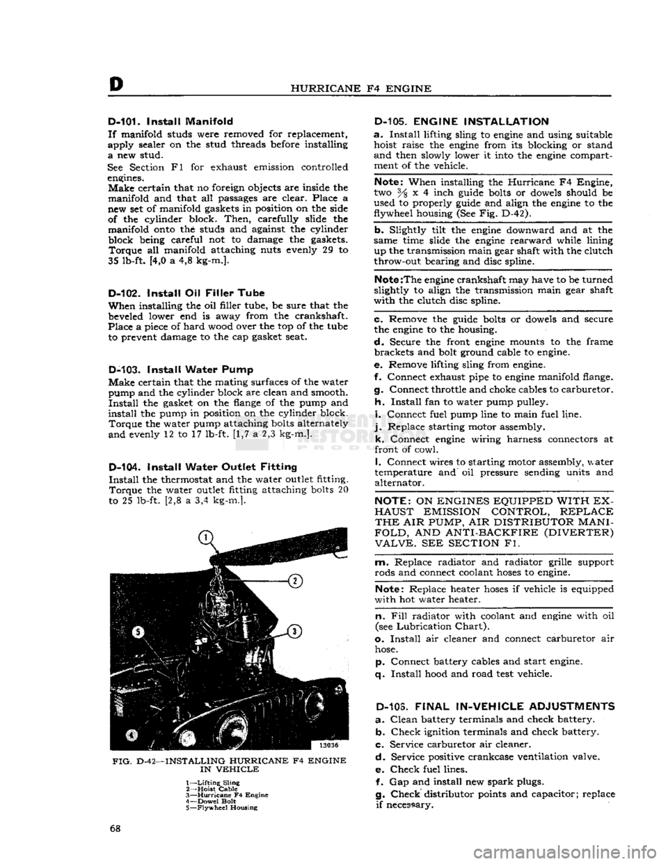
FIG.
D-42—INSTALLING HURRICANE F4 ENGINE
IN
VEHICLE
1—
Lifting
Sling
2— Hoist
Cable
3—
Hurricane
F4 Engine
4— Dowel Bolt
5—
Flywheel
Housing
D-105.
ENGINE INSTALLATION
a.
Install
lifting sling to
engine
and using suitable hoist raise the
engine
from its blocking or stand
and
then slowly lower it
into
the
engine
compartment of the vehicle.
Note:
When installing the
Hurricane
F4 Engine,
two % x 4 inch
guide
bolts
or
dowels
should be
used to properly
guide
and align the
engine
to the
flywheel housing (See Fig. D-42).
b. Slightly tilt the
engine
downward and at the
same time slide the
engine
rearward
while lining up the transmission main gear shaft with the clutch
throw-out bearing and disc spline.
Note
:The
engine
crankshaft may have to be turned
slightly to align the transmission main gear shaft
with the clutch disc spline.
c. Remove the
guide
bolts
or
dowels
and secure
the
engine
to the housing.
d.
Secure the front
engine
mounts to the frame brackets and
bolt
ground cable to
engine.
e. Remove lifting sling from
engine.
f. Connect exhaust pipe to
engine
manifold flange.
g. Connect throttle and choke cables to carburetor.
h.
Install
fan to water pump pulley.
i.
Connect fuel pump line to main fuel line,
j.
Replace starting motor assembly. k. Connect
engine
wiring harness connectors at
front of cowl.
I.
Connect wires to starting motor assembly, water
temperature and oil pressure sending units and alternator.
NOTE:
ON
ENGINES EQUIPPED WITH EX
HAUST
EMISSION CONTROL,
REPLACE
THE
AIR
PUMP,
AIR
DISTRIBUTOR
MANI
FOLD,
AND
ANTI-BACKFIRE (DIVERTER)
VALVE.
SEE
SECTION
Fl.
m. Replace radiator and radiator grille support
rods and connect coolant
hoses
to
engine.
Note:
Replace heater
hoses
if vehicle is equipped
with hot water heater.
n. Fill
radiator with coolant and
engine
with oil
(see
Lubrication
Chart).
o.
Install
air cleaner and connect carburetor air
hose.
p. Connect battery cables and start
engine,
q.
Install
hood
and road
test
vehicle.
D-103.
FINAL
IN-VEHICLE
ADJUSTMENTS
a.
Clean
battery terminals and check battery. b.
Check
ignition terminals and check battery.
c. Service carburetor air cleaner.
d.
Service positive crankcase ventilation valve.
e.
Check
fuel lines. f. Gap and install new
spark
plugs.
g.
Check
distributor
points
and capacitor; replace
if
necessary. 68
Page 70 of 376
D
HURRICANE
F4
ENGINE
D-112.
SERVICE
DIAGNOSIS
Poor
Fuel
Economy Ignition Timing Slow or Spark Advance Stuck
Carburetor
Float High
Accelerator Pump Not Properly Adjusted
High
Fuel
Pump Pressure
Fuel
Leakage
Leaky
Fuel
Pump Diaphragm
Loose Engine Mounting Causing High
Fuel
Level
in
Carburetor
Low
Compression Valves Sticking
Spark
Plugs Bad
Spark
Plug Cables Bad Weak
Coil
or Condenser Improper Valve Tappet Clearance
Carburetor
Air Cleaner Dirty
High Oil Level in Air Cleaner Dragging Brakes
Front
Wheels Out of Alignment
Tires
Improperly Inflated Inaccurate Odometer
Faulty
Fuel
Tank
Cap
Clogged
Muffler or Bent Exhaust Pipe
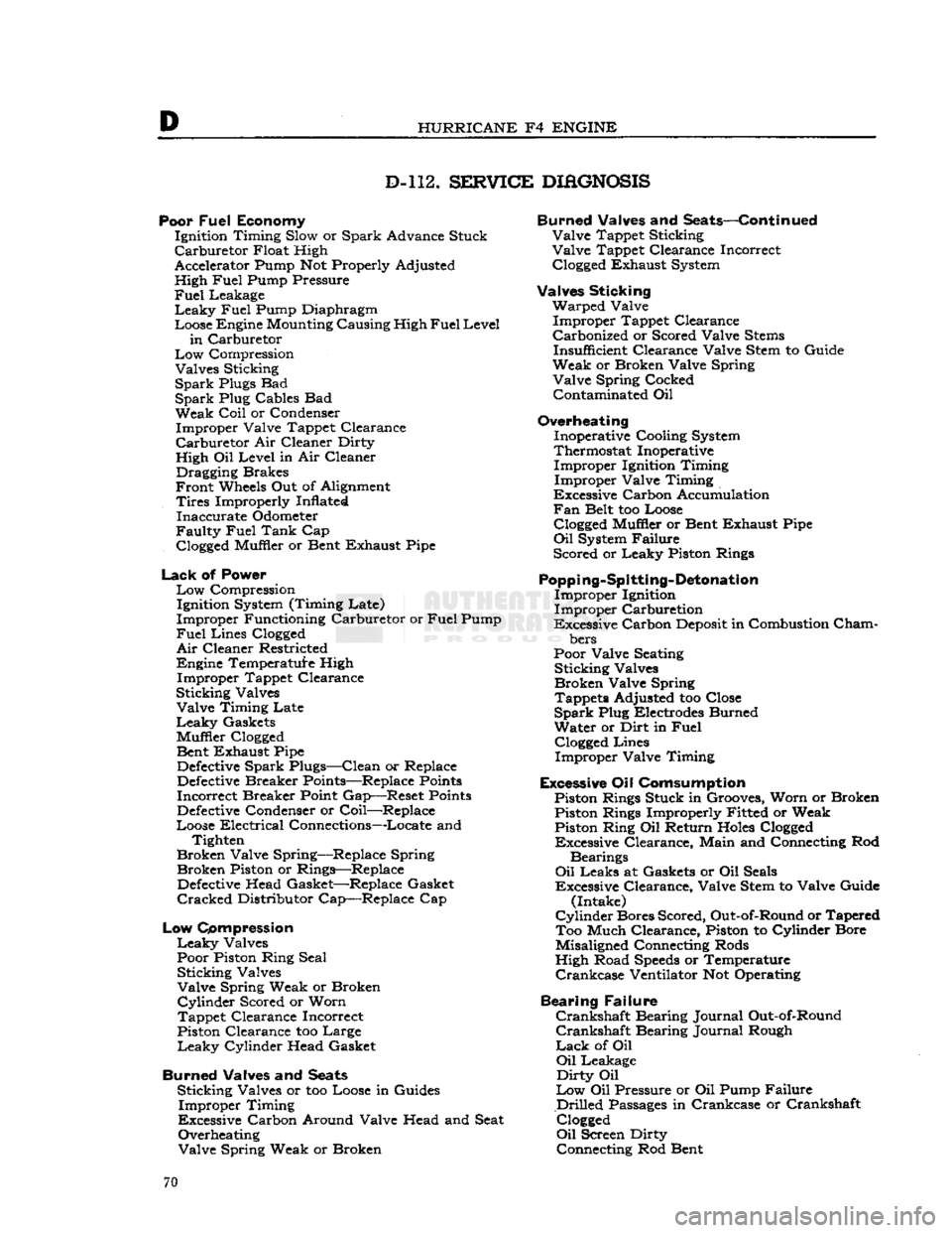
Lack
of Power
Low
Compression Ignition System (Timing Late)
Improper Functioning Carburetor or
Fuel
Pump
Fuel
Lines
Clogged
Air
Cleaner Restricted
Engine Temperature High Improper Tappet Clearance
Sticking Valves Valve Timing Late
Leaky
Gaskets
Muffler
Clogged
Bent Exhaust Pipe
Defective
Spark Plugs—Clean or Replace
Defective
Breaker Points—Replace
Points
Incorrect Breaker Point Gap—Reset
Points
Defective
Condenser or Coil—Replace
Loose Electrical Connections—Locate and Tighten
Broken Valve Spring—Replace Spring Broken Piston or Rings—Replace
Defective
Head Gasket—Replace Gasket
Cracked
Distributor Cap—Replace Cap
Low
Compression
Leaky
Valves
Poor Piston Ring Seal Sticking Valves
Valve Spring Weak or Broken
Cylinder
Scored or Worn
Tappet Clearance Incorrect
Piston Clearance too Large
Leaky
Cylinder Head Gasket
Burned Valves and
Seats
Sticking Valves or too Loose in Guides Improper Timing
Excessive Carbon Around Valve Head and Seat Overheating
Valve Spring Weak or Broken Burned Valves and Seats—Continued
Valve Tappet Sticking
Valve Tappet Clearance Incorrect
Clogged
Exhaust System
Valves Sticking Warped Valve Improper Tappet Clearance
Carbonized or Scored Valve
Stems
Insufficient Clearance Valve Stem to Guide
Weak or Broken Valve Spring Valve Spring Cocked Contaminated Oil
Overheating Inoperative Cooling System
Thermostat Inoperative Improper Ignition Timing
Improper Valve Timing
Excessive Carbon Accumulation
Fan
Belt too Loose
Clogged
Muffler or Bent Exhaust Pipe
Oil
System Failure
Scored or Leaky Piston Rings
Popping-Spitting-Detonation
Improper Ignition
Improper Carburetion
Excessive Carbon
Deposit
in Combustion
Cham
bers
Poor Valve Seating Sticking Valves
Broken Valve Spring Tappets Adjusted too Close
Spark
Plug Electrodes Burned
Water or Dirt in
Fuel
Clogged
Lines Improper Valve Timing
Excessive Oil Comsumption Piston Rings Stuck in Grooves, Worn or Broken Piston Rings Improperly Fitted or Weak Piston Ring Oil Return
Holes
Clogged
Excessive Clearance, Main and Connecting Rod
Bearings
Oil
Leaks at Gaskets or Oil Seals
Excessive Clearance, Valve Stem to Valve Guide (Intake)
Cylinder
Bores Scored, Out-of-Round or Tapered Too Much Clearance, Piston to Cylinder Bore
Misaligned Connecting Rods
High Road
Speeds
or Temperature
Crankcase
Ventilator Not Operating
Bearing Failure
Crankshaft
Bearing Journal Out-of-Round
Crankshaft
Bearing Journal Rough
Lack
of Oil
Oil
Leakage
Dirty
Oil
Low
Oil Pressure or Oil Pump Failure
Drilled
Passages
in Crankcase or Crankshaft
Clogged
Oil
Screen Dirty Connecting Rod Bent 70
Page 75 of 376
'Jeep'
UNIVERSAL SERIES
SERVICE
MANUAL
Dl
DAUNTLESS
V-6
ENGINE
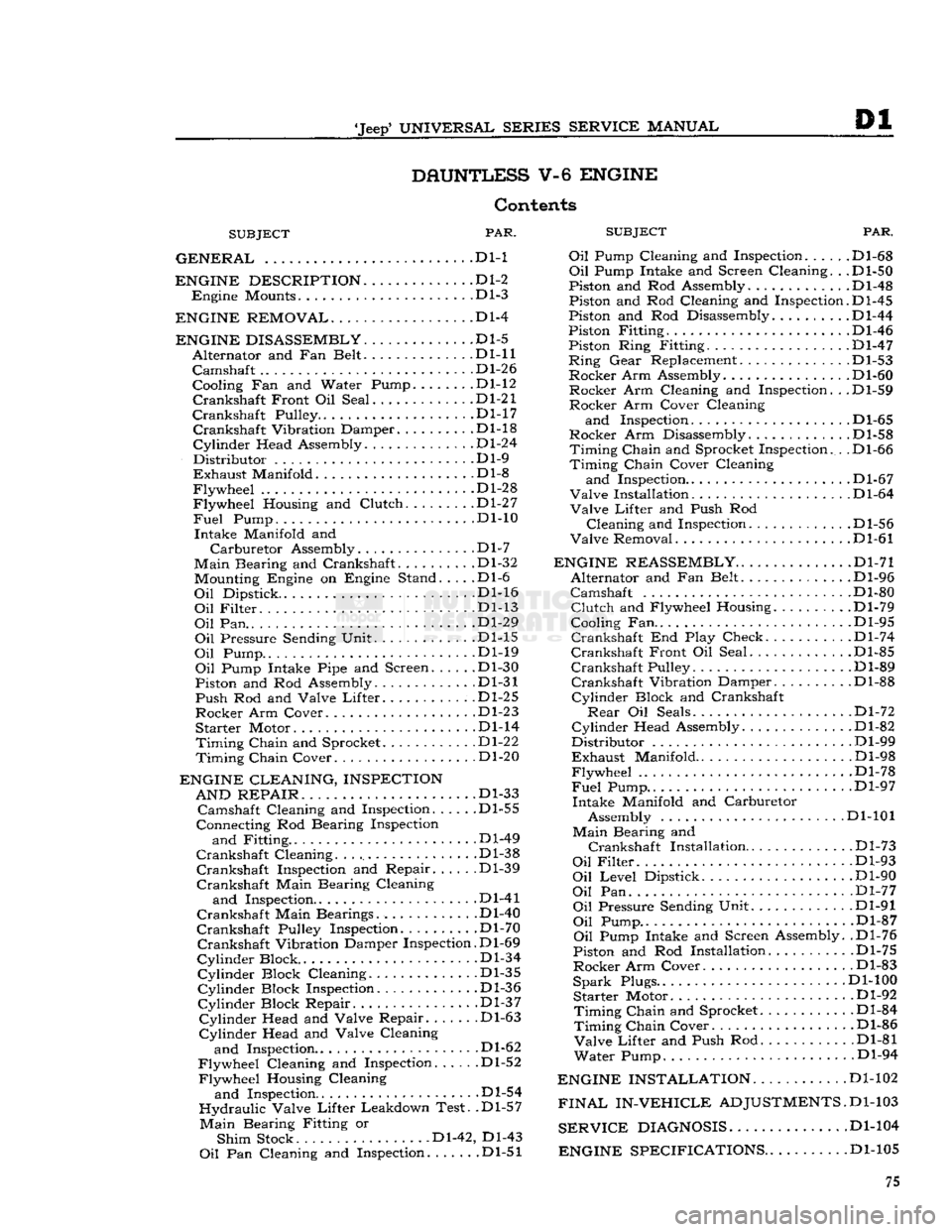
Contents
SUBJECT
PAR.
SUBJEC
GENERAL
.... . . Dl-1 Oil Pump Cl(
ENGINE DESCRIPTION
D1-2
Engine
Mounts Dl-3
ENGINE REMOVAL
Dl-4
ENGINE DISASSEMBLY
Dl-5
Alternator
and Fan Belt Dl-11
Camshaft
.... Dl-26
Cooling Fan and Water Pump.
......
.Dl-12
Crankshaft
Front Oil Seal .Dl-21
Crankshaft
Pulley D1-17
Crankshaft
Vibration Damper Dl-18
Cylinder
Head Assembly Dl-24
Distributor
Dl-9
Exhaust
Manifold .Dl-8
Flywheel
Dl-28
Flywheel
Housing and
Clutch
Dl-27
Fuel
Pump. ... . .Dl-10
Intake
Manifold and
Carburetor
Assembly.
.............
.Dl-7
Main
Bearing and Crankshaft. Dl-32 Mounting Engine on Engine Stand. . . . .Dl-6
Oil
Dipstick. Dl-16
Oil
Filter
Dl-13
Oil
Pan.. ...
.......
.Dl-29
Oil
Pressure Sending Unit Dl-15
Oil
Pump Dl-19
Oil
Pump Intake Pipe and Screen Dl-30
Piston and Rod Assembly. Dl-31
Push
Rod and Valve
Lifter.
.Dl-25
Rocker
Arm Cover Dl-23
Starter
Motor Dl-14
Timing
Chain
and Sprocket Dl-22
Timing
Chain
Cover Dl-20
ENGINE CLEANING, INSPECTION AND REPAIR
. . ... .Dl-33
Camshaft
Cleaning and Inspection Dl-55
Connecting Rod Bearing Inspection
and
Fitting .Dl-49
Crankshaft
Cleaning Dl-38
Crankshaft
Inspection and Repair Dl-39
Crankshaft
Main Bearing Cleaning
and
Inspection Dl-41
Crankshaft
Main Bearings. Dl-40
Crankshaft
Pulley Inspection. Dl-70
Crankshaft
Vibration Damper Inspection. D1-69
Cylinder
Block .Dl-34
Cylinder
Block Cleaning Dl-35
Cylinder
Block Inspection Dl-36
Cylinder
Block Repair. .Dl-37
Cylinder
Head and Valve Repair .Dl-63
Cylinder
Head and Valve Cleaning
and
Inspection.. . .Dl-62
Flywheel
Cleaning and Inspection Dl-52
Flywheel
Housing Cleaning
and
Inspection Dl-54
Hydraulic
Valve
Lifter
Leakdown Test. .Dl-57
Main
Bearing Fitting or
Shim
Stock Dl-42, Dl-43
Oil
Pan Cleaning and Inspection .Dl-51
PAR.
and
Inspection. .... .Dl-68
Oil
Pump Intake and Screen Cleaning. . .Dl-50
Piston and Rod Assembly.
...........
.Dl-48
Piston and Rod Cleaning and Inspection.D1-45
Piston and Rod Disassembly Dl-44
Piston Fitting Dl-46
Piston Ring Fitting. .Dl-47
Ring
Gear
Replacement. .Dl-53
Rocker
Arm Assembly. Dl-60
Rocker
Arm Cleaning and Inspection. . .Dl-59
Rocker
Arm Cover Cleaning
and
Inspection D1-65
Rocker
Arm Disassembly .Dl-58
Timing
Chain
and Sprocket Inspection. . .Dl-66
Timing
Chain
Cover Cleaning
and
Inspection.. . Dl-67
Valve
Installation D1-64
Valve
Lifter
and Push Rod
Cleaning
and Inspection. . Dl-56
Valve
Removal Dl-61
ENGINE REASSEMBLY
Dl-71
Alternator
and Fan Belt Dl-96
Camshaft
Dl-80
Clutch
and Flywheel Housing Dl-79
Cooling Fan.. . .Dl-95
Crankshaft
End Play Check. . Dl-74
Crankshaft
Front Oil Seal Dl-85
Crankshaft
Pulley Dl-89
Crankshaft
Vibration Damper Dl-88
Cylinder
Block and Crankshaft
Rear
Oil Seals Dl-72
Cylinder
Head Assembly .Dl-82
Distributor
Dl-99
Exhaust
Manifold Dl-98
Flywheel
.Dl-78
Fuel
Pump.. .. . Dl-97
Intake
Manifold and Carburetor Assembly Dl-101
Main
Bearing and
Crankshaft
Installation
.
Dl-73
Oil
Filter
Dl-93
Oil
Level
Dipstick Dl-90
Oil
Pan Dl-77
Oil
Pressure Sending Unit Dl-91
Oil
Pump.. .Dl-87
Oil
Pump Intake and Screen Assembly. .Dl-76
Piston and Rod Installation Dl-75
Rocker
Arm Cover. Dl-83
Spark
Plugs.. Dl-100
Starter
Motor Dl-92
Timing
Chain
and Sprocket.
..........
.Dl-84
Timing
Chain
Cover Dl-86
Valve
Lifter
and Push Rod Dl-81
Water
Pump. Dl-94
ENGINE INSTALLATION
Dl-102
FINAL
IN-VEHICLE
ADJUSTMENTS.
D1-103
SERVICE
DIAGNOSIS
Dl-104
ENGINE SPECIFICATIONS
. .Dl-105 75