spark plugs JEEP CJ 1953 Owner's Guide
[x] Cancel search | Manufacturer: JEEP, Model Year: 1953, Model line: CJ, Model: JEEP CJ 1953Pages: 376, PDF Size: 19.96 MB
Page 186 of 376
ELECTRICALJ
SYSTEM
d.
Inspect for
excessive
wear
between
centrifugal
weights
and advance cam and pivot pins.
Turn
weight
base plate in a clockwise direction until
weights
are fully extended. Release and allow
springs to return
weights
to
retard
position. Repeat several times. Springs should return
weights
to
stop
without sticking and there should be no
excessive
free
movement
in the
retard
position. Inspect
springs for distortion and fatigue.
e. Inspect cam
lobes
for scoring or
excessive
wear.
Check
weight
base plate for binding or
excessive
looseness
on distributor shaft.
f.
Check
breaker plate for
excessive
looseness
on
outside
diameter of upper distributor shaft bushing.
Check
breaker plate ground lead for poor
spot
we
Id
at plate end and for
loose
or frayed terminal con
nections.
g.
Check
for
excessive
wear
between
distributor
shaft and bushings in housing. Inspect shaft for distortion. Inspect gear for scoring of
teeth
or
excessive
wear.
h.
Inspect rod end of vacuum advance mechanism
for
excessive
wear. Push rod
into
unit as far as
possible, hold finger tightly over nipple, then re
lease
rod. After about 15 seconds, remove finger
from nipple, and
notice
if air is drawn
into
unit.
If
not, diaphragm is leaking and unit must be
replaced.
H-29.
Distributor Reassembly
Refer
to Fig. H-l5.
a.
Install
distributor
primary
lead and rubber grommet in distributor housing. Mount vacuum
advance unit on housing with two
slotted
attaching
screws; insert ground lead terminal of breaker plate under outer mounting screw.
b.
Install
felt
washer over upper shaft bushing of
distributor housing and apply a few drops of light
oil.
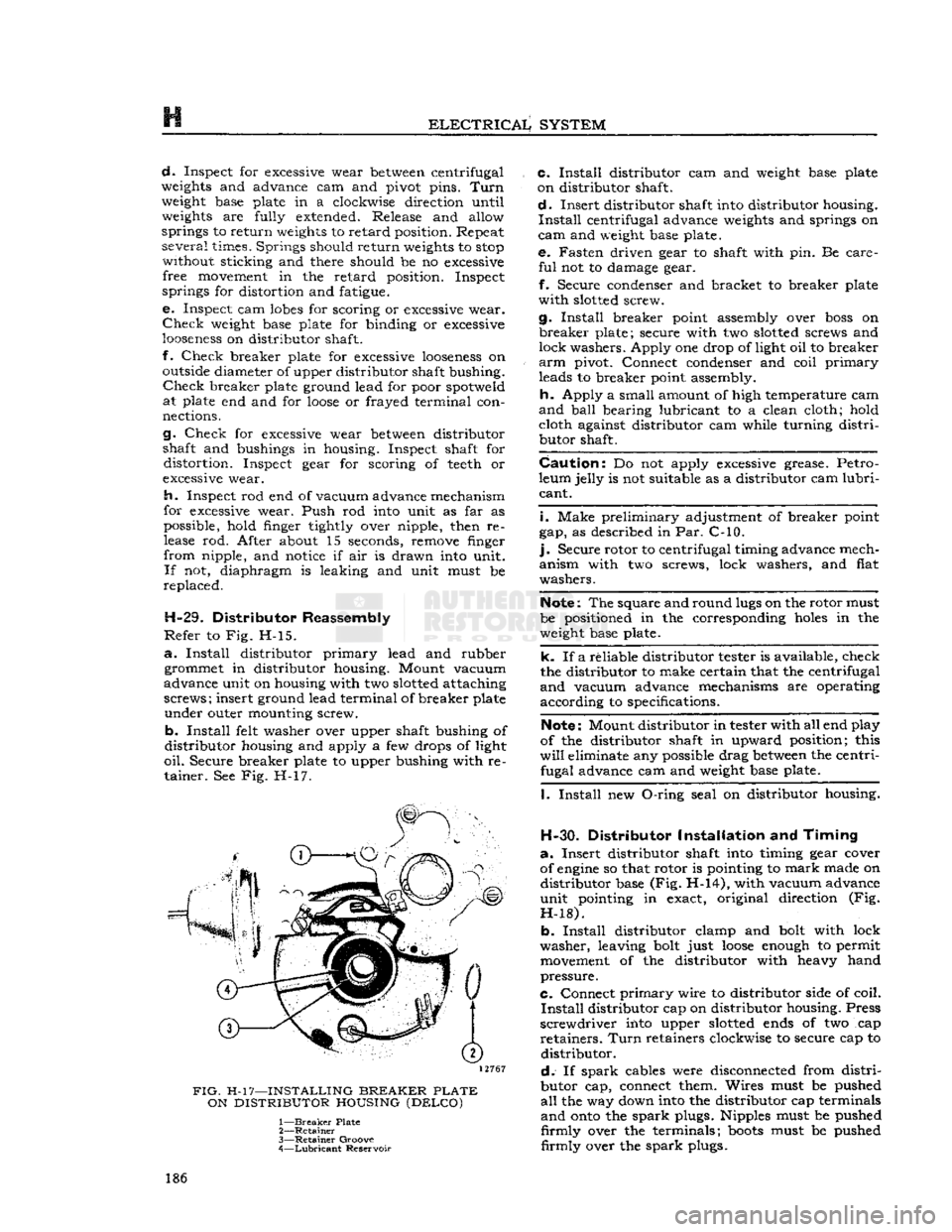
Secure breaker plate to upper bushing with re tainer. See Fig. H-17.
12767
FIG.
H-17—INSTALLING
BREAKER
PLATE
ON
DISTRIBUTOR
HOUSING
(DELCO)
1—
Breaker
Plate
2—
Retainer
3—
Retainer
Groove
4—
Lubricant
Reservoir c.
Install
distributor cam and
weight
base plate
on distributor shaft.
d.
Insert distributor shaft
into
distributor housing.
Install
centrifugal advance
weights
and springs on
cam
and
weight
base plate. e. Fasten driven gear to shaft with pin. Be care
ful
not to damage gear.
f.
Secure condenser and bracket to breaker plate
with
slotted
screw.
g.
Install
breaker point assembly over
boss
on
breaker
plate; secure with two
slotted
screws and
lock washers. Apply one drop of light oil to breaker
arm
pivot. Connect condenser and coil
primary
leads to breaker point assembly.
h.
Apply a small amount of high temperature cam
and
ball
bearing lubricant to a clean cloth; hold cloth against distributor cam while turning
distri
butor shaft.
Caution:
Do not apply
excessive
grease. Petro
leum jelly is not suitable as a distributor cam
lubri
cant.
i.
Make preliminary adjustment of breaker point
gap, as described in Par. C-10.
].
Secure rotor to centrifugal timing advance mech
anism with two screws, lock washers, and flat
washers.
Note:
The square and round
lugs
on the rotor must
be positioned in the corresponding
holes
in the
weight
base plate.
k. If a reliable distributor tester is available, check
the distributor to make certain that the centrifugal
and
vacuum advance mechanisms are operating
according to specifications.
Note:
Mount distributor in tester with all end play
of the distributor shaft in upward position; this
will
eliminate any possible drag
between
the centri fugal advance cam and
weight
base plate.
I.
Install
new
O-ring
seal on distributor housing.
H-30.
Distributor
Installation
and
Timing
a.
Insert distributor shaft
into
timing gear cover
of
engine
so that rotor is pointing to
mark
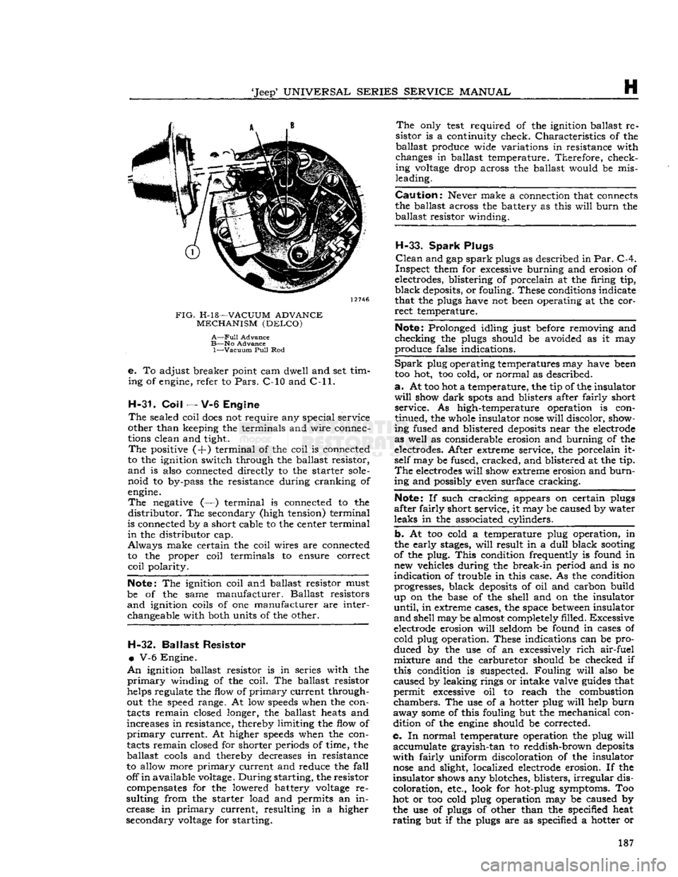
made on distributor base (Fig. H-14), with vacuum advance
unit pointing in exact, original direction (Fig.
H-18).
b.
Install
distributor clamp and
bolt
with lock
washer, leaving
bolt
just
loose
enough
to permit
movement
of the distributor with heavy hand
pressure.
C.
Connect
primary
wire to distributor side of coil.
Install
distributor cap on distributor housing. Press
screwdriver
into
upper
slotted
ends
of two cap
retainers.
Turn
retainers clockwise to secure cap to distributor.
d.
If
spark
cables were disconnected from
distri
butor cap, connect them. Wires must be pushed
all
the way down
into
the distributor cap terminals
and
onto
the
spark
plugs. Nipples must be pushed
firmly
over the terminals;
boots
must be pushed
firmly
over the
spark
plugs. 186
Page 187 of 376
'Jeep'
UNIVERSAL
SERIES SERVICE
MANUAL
H
12746
FIG.
H-l8—VACUUM
ADVANCE
MECHANISM
(DELCO)
A—Full
Advance
B—No
Advance
1—Vacuum
Pull
Rod
e.
To adjust breaker point cam dwell and set tim
ing of engine, refer to
Pars.
C-10 and
C-ll.
H-31. Coil
— V-6 Engine
The
sealed coil
does
not require any special service
other than keeping the terminals and wire connec
tions clean and tight.
The
positive (+) terminal of the coil is connected
to the ignition switch through the ballast resistor,
and
is also connected directly to the starter
sole
noid to by-pass the resistance during cranking of
engine.
The
negative (—) terminal is connected to the
distributor.
The secondary (high tension) terminal
is connected by a short cable to the center terminal
in
the distributor cap.
Always
make certain the coil wires are connected to the proper coil terminals to ensure correct
coil
polarity.
Note:
The ignition coil and ballast resistor must
be of the same manufacturer. Ballast resistors
and
ignition coils of one manufacturer are interchangeable with both units of the other. H-32.
Ballast
Resistor
•
V-6 Engine.
An
ignition ballast resistor is in series with the
primary
winding of the coil. The ballast resistor
helps regulate the flow of
primary
current through
out the speed range. At low
speeds
when the con
tacts remain closed longer, the ballast heats and
increases in resistance, thereby limiting the flow of
primary
current. At higher
speeds
when the con
tacts remain closed for shorter periods of time, the ballast
cools
and thereby decreases in resistance
to allow more
primary
current and reduce the
fall
off
in
available voltage.
During
starting, the resistor compensates for the lowered battery
voltage
re
sulting from the starter load and permits an in crease in
primary
current, resulting in a higher
secondary
voltage
for starting.
The
only
test
required of the ignition ballast re
sistor is a continuity check. Characteristics of the ballast produce wide variations in resistance with
changes in ballast temperature. Therefore, check ing
voltage
drop across the ballast would be mis
leading.
Caution:
Never make a connection that connects
the ballast across the battery as this
will
burn
the ballast resistor winding.
H-33.
Spark
Plugs
Clean
and gap
spark
plugs as described in
Par.
C-4.
Inspect them for excessive burning and erosion of
electrodes, blistering of porcelain at the firing tip,
black
deposits, or fouling. These conditions indicate
that the plugs have not been operating at the cor
rect
temperature.
Note:
Prolonged idling just before removing and
checking the plugs should be avoided as it may
produce false indications.
Spark
plug operating temperatures may have been
too hot, too cold, or normal as described.
a.
At too hot a temperature, the tip of the insulator
will
show
dark
spots
and blisters after fairly short service. As high-temperature operation is con
tinued, the whole insulator
nose
will
discolor, show
ing fused and blistered
deposits
near the electrode
as well as considerable erosion and burning of the
electrodes. After extreme service, the porcelain it self may be fused, cracked, and blistered at the tip.
The
electrodes
will
show extreme erosion and
burn
ing and possibly even surface cracking.
Note:
If such cracking appears on certain plugs
after fairly short service, it may be caused by water
leaks in the associated cylinders.
b. At too cold a temperature plug operation, in
the early
stages,
will
result in a
dull
black
sooting
of the plug.
This
condition frequently is found in new vehicles during the break-in period and is no
indication of trouble in this case. As the condition progresses, black
deposits
of oil and carbon build
up on the base of the shell and on the insulator
until,
in extreme cases, the space
between
insulator
and
shell may be almost completely filled. Excessive
electrode erosion
will
seldom be found in cases of cold plug operation. These indications can be pro
duced by the use of an excessively
rich
air-fuel mixture and the carburetor should be checked if
this condition is suspected. Fouling
will
also be
caused by leaking rings or intake valve
guides
that
permit excessive oil to reach the combustion
chambers.
The use of a hotter plug
will
help
burn
away
some
of this fouling but the mechanical con dition of the
engine
should be corrected.
c. In normal temperature operation the plug
will
accumulate grayish-tan to reddish-brown
deposits
with
fairly uniform discoloration of the insulator
nose
and slight, localized electrode erosion. If the
insulator shows any blotches, blisters,
irregular
dis
coloration, etc., look for hot-plug symptoms. Too
hot or too cold plug operation may be caused by
the use of plugs of other than the specified heat
rating
but if the plugs are as specified a hotter or 187
Page 188 of 376
H
ELECTRICAL
SYSTEM
colder plug may be desirable. However, under- or
over-heating is usually caused by factors other than the type of
spark
plugs and the cause should be determined before changing plugs. The design of the
engine
calls for plugs equivalent to Champion
J-8
for F4
engines
and
A.C.
44S or
UJ12Y
Champ
ion for the V6 engines, (as installed in production)
though any factor that consistently affects
engine
operating temperature may cause this requirement
to change. Overheating may be caused by in sufficient tightening of the plug in the head, which interferes with the flow of heat away from the firing
tip.
If this is the case, the plug gasket
will
show very
little flattening. Over-tightening, in
turn,
will
pro duce too easy a heat flow path and result in cold
plug operation.
This
will
be evident by excessive
flattening
and
deformation of the gasket.
Prevailing
temperatures, condition of the cooling system, and
air-fuel
mixture can affect the
engine
operating temperature and should be taken into consideration.
H-34.
GENERATOR
— F4
ENGINE
The
generator is an air-cooled, two-brush unit
which
cannot be adjusted to increase or decrease output. For replacement,
voltage
regulator and generator must be matched for
voltage
and capa
city,
polarity, and common source of manufacture.
Otherwise,
either a
loss
of ampere capacity or a
burned
out generator
will
result. Generators for
these
vehicles are 12-volt. Par. H-l explains the 12-volt system. Refer to the specifications at the
end of this section for information on correct generator rating for a specific model series.
The
circuit
breaker,
voltage
regulator, and current-
limiting
regulator are built into one combination
unit.
Because the regulator and battery are part
of the generator
circuit,
the output of the generator
depends upon the
state
of charge and temperature
of the battery.
With
a discharged battery, the
output
will
be high, decreasing proportionally as the battery
becomes
charged. For service informa
tion covering current regulator see Par. H-41.
H-36.
Generator
Maintenance
A
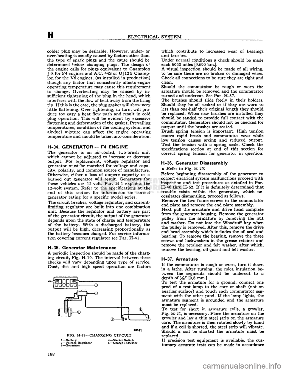
periodic inspection should be made of the charg
ing
circuit,
Fig. H-l9. The interval
between
these
checks
will
vary
depending upon type of service.
Dust,
dirt
and high speed operation are factors 10541
FIG.
H-19—CHARGING
CIRCUIT
1—
Battery
4-—Starter Switch
2—
Voltage
Regulator 5-—Charge Indicator
3—
Generator
which
contribute to increased wear of bearings
and
brushes.
Under
normal conditions a check should be made
each 6000 miles
[9.600
km.].
A
visual inspection should be made of all wiring,
to be sure there are no broken or damaged wires.
Check
all connections to be sure they are tight and
clean.
Should
the commutator be rough or worn the
armature
should be removed and the commutator
turned
and undercut. See Par. H-37.
The
brushes should slide freely in their holders.
Should
they be oil soaked or if they are worn to
less
than one-half their original length they should
be replaced. When new brushes are installed they should be sanded to provide
full
contact with the
commutator. Generators should not be checked for
output until the brushes are seated.
Brush
spring tension is important. High tension causes
rapid
brush and commutator wear while
low tension causes arcing and reduced output.
Test
the tension with a spring scale.
Check
the
specifications section at end of this section for
correct
spring tension for generator in question.
H-36.
Generator Disassembly
•
Refer to Fig. H-20:
Before beginning disassembly of the generator to
correct
electrical system malfunctions proceed with
inspection and
test
procedures as detailed in Par.
H-46
thru
H-62. If it is definitely determined that trouble exists within the generator, which necessitates dismantling, proceed as follows. Remove the two frame screws in the commutator
end plate and remove the end plate assembly. Next
pull
the armature and drive head complete
from
the generator housing. Remove the generator pulley from the armature by removing the nut
and
washer. Do not
lose
the Woodruff key when
the pulley is removed. After this, remove the drive
end head assembly which includes the oil seal and
bearing.
To remove the bearing, remove the three
screws and lockwashers in the grease retainer and remove the retainer and felt washer, after which,
remove the bearing, oil guard and felt washer.
H-37.
Armature
If
the commutator is rough or worn,
turn
it down
in
a lathe. After turning, the mica insulation be tween the
segments
should be undercut to a depth of 34* [0,8 mm.].
To
test
the armature for a ground, connect one
prod
of a
test
lamp to the core or shaft (not on
bearing
surface) and touch each commutator
seg
ment with the other prod. If the lamp lights, the
armature
segment
is grounded and the armature must be replaced.
To
test
for short in armature coils, a growler,
Fig.
H-21, is necessary. Place the armature on the growler and lay a thin steel strip on the armature
core.
The armature is then rotated slowly by hand
and
if a coil is shorted, the steel strip
will
vibrate.
Should
a coil be shorted the armature must be
replaced.
If
precision
test
equipment is available, the cus
tomary
accurate
tests
can be made in accordance 188
Page 224 of 376
H
ELECTRICAL
SYSTEM
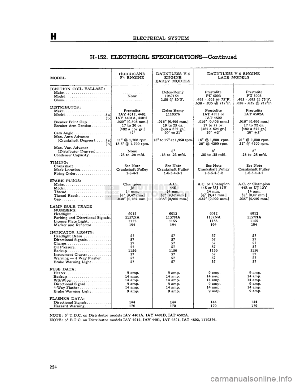
H-152.
ELECTRICAL
SPECIFICATIONS—Continued
HURRICANE DAUNTLESS
V-6
DAUNTLESS
V-6 ENGINE
MODEL -
F4
ENGINE
ENGINE
LATE
MODELS
EARLY
MODELS
IGNITION
COIL
BALLAST
]Make Delco-Remy
Prestolite Prestolite
Model
None
1957154
PU
5003
PU
5003
Ohms • • 1.80 @
80°F.
.495 - .605 @
75°F.
.495 - .605 @
75°F.
1.80 @
80°F.
.638 - .835 @
212°F.
.638 - .835 @
212°F.
DISTRIBUTOR:
Prestolite Delco-Remy Prestolite Prestolite
Model
•
(a)
LAY
4012, 4401
1110376
I
AT
4501 or
IAT
4502A
(b)
I
AY
4401A, 44011
IAT
4502
Breaker
Point Gap (b)
.020"
[0,508
mm.] .016"
[0,406
mm.] .016"
[0,406
mm.]
.016"
[0,406
mm.]
Breaker
Arm Tension. ..... 17 to 20 oz.
19 to 23 oz. 17 to 22 oz. 17 to 22 oz.
[482 a 567 gr.] [538 a 652 gr.] [482 a 624 gr.]
[482 a 624 gr.]
42° 29°
to 31°
29°
±3°
29°
±3°
Max.
Auto Advance
(Crankshaft
Degrees) •(a)
11°
@ 1,700 rpm.
13°
to
15°
at 1,950 rpm.
16°
@ 1,800 rpm.
21°
(2 1,800 rpm.
(Crankshaft
Degrees)
(b)
13.5°
@ 1,700 rpm.
26°
@
4200
rpm.
32°
@
4200
rpm.
Max.
Vac. Advance go
(Distributor Degrees)., . .
None
8° 8°
go
Condenser Capacity. . .25 to .28 mfd. .18 to .23 mfd. .25 to .28 mfd. .25 to .28 mfd.
TIMING:
Crankshaft
See
Note
See
Note
See
Note
See
Note
Mark
Location............
Crankshaft
Pulley
Crankshaft
Pulley
Crankshaft
Pulley
Csankshaft
Pulley
Firing
Order
1-3-4-2
1-6-5-4-3-2
1-6-5-4-3-2 1-6-5-4-3-2
SPARK PLUGS:
Make
Champion
A.C. A.C.
or Champion
A.C.
or Champion
J8
44S
44S or UJ 12Y 44S or UJ 12Y
Thread
14 mm.
14 mm. 14 mm. 14 mm.
Thread
Reach
Vz"
[9,47 mm.]
%"
[9,47 mm.]
¥%"
[9,47 mm.]
V8" [9,47 mm.]
Gap
.030"
[0,762
mm.]
.035"
[0,900
mm.] .035"
[0,900
mm.] .035"
[0,900
mm.|
LAMP BULB TRADE
NUMBERS:
Headlight 6012
6012 6012 6012
Parking
and Directional Signals. 1157NA
1157NA 1157NA 1157NA
License
Plate Light........ 1155
1155 1155 1155
Marker
and Reflector 194
194 194 194
INDICATOR LIGHTS:
57 57 57 57
Directional Signals........ 57
57 57 57
Charge
57
57 57 57
57 57 57 57
1156 1156 1156 1156
Instrument Cluster 57 57 57 57
Warning
— 4 Way Flasher. . 57
57 57 57
Brake
Warning Light 57
57 57 57
FUSE
DATA:
Heater 9 amp. 9 amp. 9 amp. 9 amp.
Backup
14 amp. 14 amp. 14 amp. 14 amp.
WS/Wiper.
14 amp. 14 amp. 14 amp. 14 amp.
Directional Signal 9 amp. 9 amp. 9 amp. 9 amp.
4-Way Flasher 14 amp. 14 amp. 14 amp. 14 amp.
Brake
Warning Light 9 amp. 9 amp. 9 map. 9 amp.
FLASHER
DATA:
Directional Signals. 144
144 144 144
Hazzard
Warning. 170
170 170 170
NOTE:
0°
T.D.C.
on Distributor
models
IAY 4401A, IAY 4401B, IAT 4502A.
NOTE:
5°
B.T.C.
on Distributor
models
IAY 4012, IAY 4401, IAT 4501, IAT 4502,
1110376.
224
Page 362 of 376
u
MISCELLANEOUS
U-12.
STANDARD
AND
RECOMMENDED TOOLS
(Continued)
Tool
Description
CLUTCH
W-296 Fixture — Adjusting
TRANSMISSION
C-3201
- A
Lo-Jack
— Floor Type
AXLE
C-637 Puller — Axle Shaft & Oil Seal
STEERING
DD-428 Gauge — Camber & Caster
DD-435 Turntables — Wheel Alignment C-3479 Gauge & Scribe — Toe-in Checking
BRAKES
C-416 Clamps — Brake Cylinder Retaining C-3080 Hone — Brake Cylinder
C-3496-B Bleeder — Hydraulic Pressure Type C-3785 Remover & Installer — Brake Return Spring
C-3920 Micrometer — Brake Drum Checking
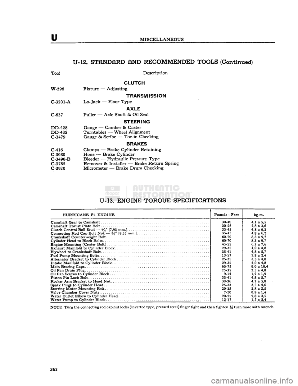
U-13.
ENGINE TORQUE SPECIFICATIONS HURRICANE
F4
ENGINE
Pounds - Feet
kg-m.
30-40
4,1
a
5,5
Camshaft
Thrust Plate Bolt
20-26
2,8
a
3,6
Clutch
Control
Ball
Stud — [7,93 mm.]
35-45
4,8
a
6,2
Connecting Rod Cap Bolt Nut — y8" [9,53 mm.|
35-45
4,8
a
6,2
60-70
8,3
a
9,7
Cylinder
Head to Block Bolts
60-70
8,3
a
9,7
45-55
6,2
a
7,6
29-35
4,0
a
4,8
Flywheel
to Crankshaft Bolt. 35-41
4,8
a
5,7
Fuel
Pump Mounting Bolts 13-17 1,8
a
2,4
Alternator Bracket to Cylinder Block.
25-35
3,5
a
4,8
29-35
4,0
a
4,8
Main
Bearing
Caps.
.
65-75
9,0
a
10,4
Oil
Pan
Drain
Plug
25-35
3,5
a
4,8
9-14 1,2
a
1,9
Piston Pin
Lock
Bolt 35-41
4,8
a
5,7
30-36
4,1
a
5,0
Spark
Plugs to Cylinder Head
25-33
3,5
a
4,6
Starting Motor Mounting Bolt.
20-25
2,8
a
3,5
7-10 0,9
a
1,4
Water
Outlet Elbow to Cylinder Head
20-25
2,8
a
3,5
Water
Pump to Cylinder Block 12-17
1,7
a
2,4
NOTE:
Turn
the connecting rod cap nut locks (inverted type, pressed
steel)
finger
tight
and then
tighten
% turn more with wrench
362
Page 363 of 376
'Jeep*
UNIVERSAL SERIES
SERVICE
MANUAL
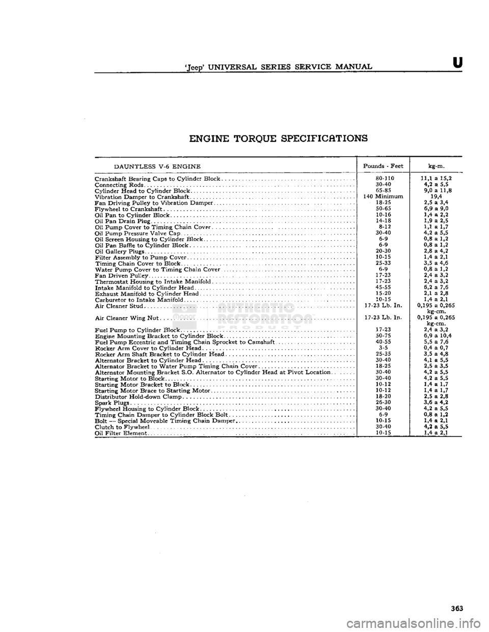
U ENGINE TORQUE SPECIFICATIONS
DAUNTLESS
V-6
ENGINE
Pounds
- Feet
kg-m.
80-110
11,1 a 15,2
30-40
4,2 a 5,5
65-85
9,0 a 11,8
140 Minimum 19,4
18-25 2,5 a 3,4
50-65
6,9 a 9,0
10-16 1,4 a 2,2
14-18 1,9 a 2,5
8-12 1,1 a 1,7
30-40
4,2 a 5,5
6-9 0,8 a 1,2
6-9 0,8 a 1,2
20-30
2,8 a 4,2
10-15 1,4 a 2,1
25-33
3,5 a 4,6
6-9 0,8 a 1,2
17-23 2,4 a 3,2
17-23 2,4 a 3,2
45-55
6,2 a 7,6
15-20 2,1 a 2,8
10-15 1,4 a 2,1
17-23
Lb.
In. 0,195 a
0,265
kg-cm.
17-23 Lb. In. 0,195 a
0,265
kg-cm.
17-23 2,4 a 3,2
50-75
6,9 a 10,4
40-55
5,5 a 7,6
3-5 0,4 a 0,7
25-35
3,5 a 4,8
30-40
4,1 a 5,5
18-25 2,5 a 3,5
30-40
4,2 a 5,5
30-40
4,2 a 5,5
10-12 1,4 a 1,7
10-12 1,4 a 1,7
18-20 2,5 a 2,8
26-30
3,6 a 4,2
30-40
4,2 a 5,5
6-9 0,8 a 1,2
10-15 1,4 a 2,1
30-40
4,2 a 5,5
10-15 1,4 a 2,1
Crankshaft
Bearing Caps to Cylinder Block.
Connecting Rods.
Cylinder
Head to Cylinder Block
Vibration Damper to Crankshaft
Fan
Driving Pulley to Vibration Damper
Flywheel to Crankshaft
Oil
Pan to Cylinder Block
Oil
Pan Drain Plug
Oil
Pump Cover to Timing Chain Cover. . .
Oil
Pump Pressure Valve Cap
Oil
Screen Housing to Cylinder Block
Oil
Pan Baffle to Cylinder Block
Oil
Gallery Plugs.
Filter
Assembly to Pump Cover
Timing
Chain Cover to Block
Water Pump Cover to Timing Chain Cover.
Fan
Driven Pulley Thermostat Housing to Intake Manifold. . . Intake Manifold to Cylinder Head
Exhaust
Manifold to Cylinder Head
Carburetor
to Intake Manifold
Air
Cleaner Stud
Air
Cleaner Wing Nut.
Fuel
Pump to Cylinder Block . . Engine
Mounting
Bracket to Cylinder Block
Fuel
Pump Eccentric and Timing Chain Sprocket to Camshaft
Rocker Arm Cover to Cylinder Head Rocker Arm Shaft Bracket to Cylinder Head
Alternator Bracket to Cylinder Head
Alternator Bracket to Water Pump Timing Chain Cover Alternator
Mounting
Bracket S.O. Alternator to Cylinder Head at Pivot Location.
Starting Motor to Block Starting Motor Bracket to Block
Starting Motor Brace to Starting Motor Distributor
Hold-down
Clamp
Spark
Plugs
Flywheel Housing to Cylinder Block
Timing
Chain Damper to Cylinder Block Bolt.
Bolt — Special
Moveable
Timing Chain Damper
Clutch
to Flywheel
Oil
Filter Element .' 363
Page 372 of 376
ALPHABETICAL
INDEX
SUBJECT
PAR.
SUBJECT
PAR.
Ignition Cable Test C-l9 Ignition
Coil
C-20, H-19, H-31
Ignition Switch H-89 Ignition System H-3
Ignition
Timing
C-14, H-18, H-30 Ignition Wires C-18
Intake Manifold '." Dl-7, Dl-101
Instrument, Electrical H-122
L
License Plate Light H-l36
Lighting
System H-l25
Light
Switch, Main . H-l 26
Lubrication
B-l
Lubrication,
Body B-65
Lubrication
Maintenance Schedule B-8
Lubrication
of Optional Equipment B-69
Lubrication,
Off Highway B-79
Lubrication,
Special. B-2
M
Main
Bearings D-43, D-82, Dl-32, Dl-42, Dl-73
Main
Light Switch. H-l26
Maintenance, Clutch 1-2 Maintenance, Exhaust System.,
-
F-4
Manifold, Exhaust -F-6 Manifold, Intake D-7, Dl-101
Manifold Vacuum Check. .C-24 Master Cylinder, Brake B-40, P-2, P-20
Miscellaneous Data U-16 Mountings, Engine • • •
-
D-3, Dl-3
Muffler. F-9
O
Oil
Filter B-10, B-ll,
D-lll,
Dl-13, Dl-93
Oil
Pan D-19, D-66, D-97, Dl-29, Dl-51, Dl-77
Oil
Pump. D-14, D-65, D-93, Dl-19, Dl-50, Dl-87
P
Paint and
Trim
Plate • • A-7
Parking
Brake Adjustment P-ll
Parking
Lights H-133
Pilot Bushing, Crankshaft D-70, 1-8
Pintle Hook U-7
Pistons D-20, D-95, Dl-31, Dl-48, Dl-75 Piston Rings. • • •
•
D-37, Dl-47 Positive Crankcase Vent. B-13, C-6, D-110
Powr-Lok
Differential B-72, N-20
Primary
Circuit,
Electrical H-4 Propeller Shaft U-Joints .B-58, L-2, L-3 Propeller Shaft Specifications <:' L-7
R
Radiator
B-28, B-29, G-5
Radiator
Hoses. G-7
Radiator
Pressure Cap G-4
Rear
Axle. B-50, B-51, B-52, N-9
Rear
Axle Reassembly • N-l
7
Rear
Axle Disassembly N-l
2
Rear
Axle Pinion Adjustment N-l6
Rear
Axle Shaft N-2, N-3
Rear
Bearing Seal, Crankshaft D-63, D-85, Dl-62
Rear
Wheel Bearings B-56, B-57, N-4, Q-3
Regulator Test, Voltage H-47, H-71
Rocker
Arm Cover.. . Dl-65
Rocker
Arms D-16, D-74, D-99, Dl-60 Rotor, Alternator H-76, H-79
S
Seats
• T-8 Secondary
Circuit,
Electrical H-5
Shock Absorbers B-48, S-7
Solenoid Switch. H-l21 Special Lubricants B-2
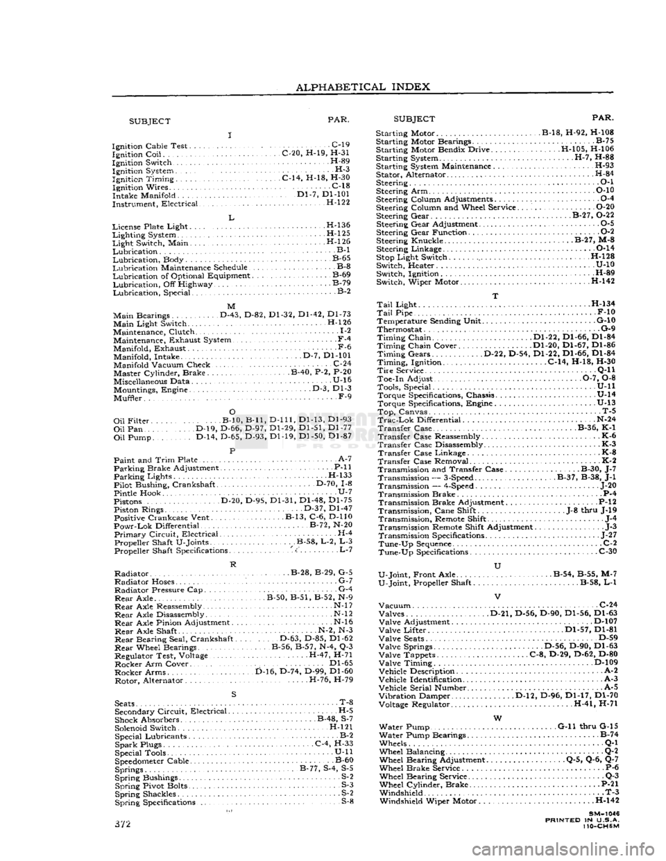
Spark
Plugs C-4, H-33
Special Tools • U-ll
Speedometer
Cable B-60 Springs B-77, S-4, S-5
Spring
Bushings S-2
Spring
Pivot Bolts S-3
Spring
Shackles S^2
Spring
Specifications S-8 372 Starting Motor B-18, H-92, H-108
Starting Motor Bearings B-75
Starting Motor Bendix Drive H-105, H-106
Starting System H-7, H-88
Starting System Maintenance H-93 Stator, Alternator H-84
Steering • • •
•
O-l
Steering Arm P-10
Steering Column Adjustments 0-4
Steering Column and Wheel Service O-20 Steering Gear. . B-27, 0-22
Steering Gear Adjustment 0-5
Steering Gear Function 0-2
Steering Knuckle. B-27, M-8 Steering Linkage 0-14
Stop
Light Switch H-128
Switch, Heater U-10 Switch, Ignition H-89
Switch, Wiper Motor H-142
T
Tail
Light . H-134
Tail
Pipe F-10 Temperature Sending Unit G-10
Thermostat G-9
Timing
Chain Dl-22, Dl-66, Dl-84
Timing
Chain Cover Dl-20, Dl-67, Dl-86
Timing
Gears D-22, D-54, Dl-22, Dl-66, Dl-84
Timing,
Ignition. C-14, H-18, H-30
Tire
Service . •
•
Q-l
1
Toe-in Adjust 0-7, 0-8 Tools, Special. . .
........
U-ll Torque Specifications, Chassis U-14
Torque Specifications, Engine .U-13
Top,
Canvas. T-5
Trac-Lok
Differential N-24
Transfer
Case B-36, K-1
Transfer
Case Reassembly K-6
Transfer
Case Disassembly K-3
Transfer
Case Linkage - K-8
Transfer
Case Removal K-2 Transmission and Transfer Case. B-30, J-7 Transmission —
3-Speed
B-37, B-38, J-l
Transmission —
4-Speed
... J-20
Transmission Brake P-4 Transmission Brake Adjustment P-l
2
Transmission,
Cane Shift .J-8 thru J-19
Transmission,
Remote Shift J-4
Transmission Remote Shift Adjustment J-3
Transmission Specifications
-
J-27
Tune-Up
Sequence
C-2
Tune-Up
Specifications C-30
U
U-Joint, Front Axle . . B-54, B-55, M-7
U-Joint, Propeller Shaft B-58, L-l
Vacuum
C-24 Valves D-21, D-56, D-90, Dl-56, Dl-63
Valve
Adjustment D-107
Valve
Lifter Dl-57, Dl-81
Valve
Seats
D-59
Valve
Springs .D-56, D-90, Dl-63
Valve
Tappets C-8, D-29, D-62, D-80
Valve
Timing D-109
Vehicle Description A-2
Vehicle Identification A-3
Vehicle Serial Number. A-5
Vibration
Damper D-l2, D-96, Dl-17, Dl-70 Voltage Regulator. H-41, H-71
W
Water Pump G-ll thru G-15
Water Pump Bearings B-74
Wheels Q-l
Wheel Balancing Q-2 Wheel Bearing Adjustment Q-5, Q-6, Q-7
Wheel Brake Service P-6 Wheel Bearing Service Q-3
Wheel Cylinder, Brake P-21 Windshield T-3 Windshield Wiper Motor . .H-142
SM-1046
PRINTED
IN U.S.A.
110-CH6M