wheel JEEP CJ 1953 User Guide
[x] Cancel search | Manufacturer: JEEP, Model Year: 1953, Model line: CJ, Model: JEEP CJ 1953Pages: 376, PDF Size: 19.96 MB
Page 37 of 376
'Jeep9
UNIVERSAL SERIES SERVICE
MANUAL
D HURRICANE
F4
ENGINE
Contents
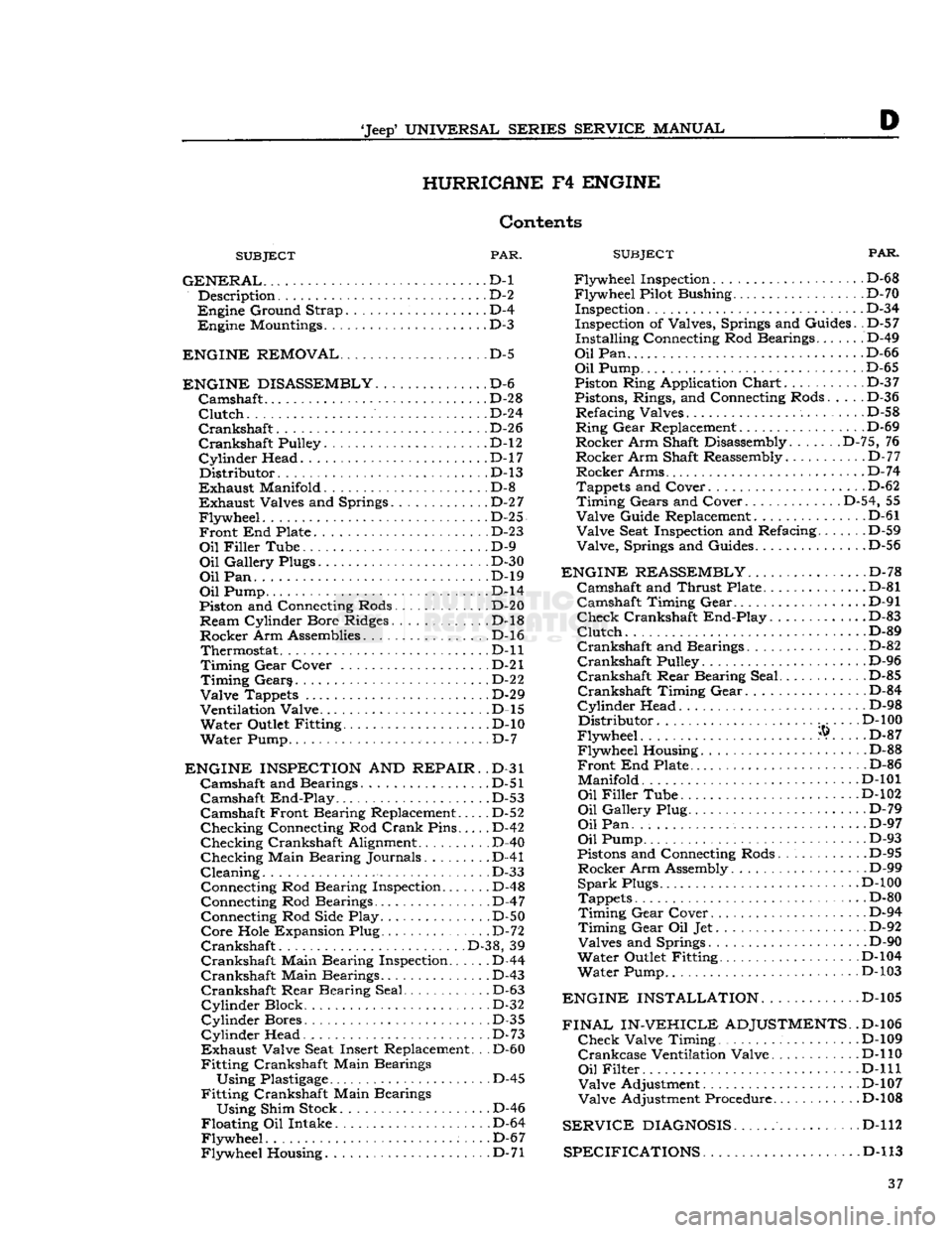
SUBJECT
PAR.
GENERAL...
D-l Description D-2
Engine
Ground Strap D-4
Engine
Mountings D-3
ENGINE REMOVAL
D-5
ENGINE DISASSEMBLY
D-6
Camshaft
.......
D-28
Clutch
D-24
Crankshaft.
D-26
Crankshaft
Pulley. D-l2
Cylinder
Head. .D-17
Distributor.
.D-13
Exhaust
Manifold D-8
Exhaust
Valves and Springs D-2
7
Flywheel.
. D-25
Front
End Plate D-23
Oil
Filler
Tube D-9
Oil
Gallery Plugs D-30
Oil
Pan. . ...D-19
Oil
Pump D-l4
Piston and Connecting Rods. . . D-20
Ream
Cylinder Bore Ridges. D-l8
Rocker
Arm Assemblies D-l6 Thermostat D-ll
Timing
Gear
Cover . . D-21
Timing
Gears D-22
Valve
Tappets D-29
Ventilation Valve D-l5
Water
Outlet Fitting D-10
Water
Pump D-7
ENGINE INSPECTION
AND
REPAIR.
.D-31
Camshaft
and Bearings. D-51
Camshaft
End-Play
. . .D-53
Camshaft
Front Bearing Replacement..... D-52
Checking
Connecting Rod
Crank
Pins D-42
Checking
Crankshaft Alignment .
.
D-40
Checking
Main Bearing Journals. D-41
Cleaning.
. D-33 Connecting Rod Bearing Inspection D-48
Connecting Rod Bearings D-47 Connecting Rod Side Play D-50
Core
Hole Expansion Plug D-72
Crankshaft
.
.
D-38, 39
Crankshaft
Main Bearing Inspection D-44
Crankshaft
Main Bearings D-43
Crankshaft
Rear
Bearing Seal D-63
Cylinder
Block D-32
Cylinder
Bores D-35
Cylinder
Head. . . D-73
Exhaust
Valve Seat Insert Replacement. .
.
D-60
Fitting
Crankshaft Main Bearings
Using
Plastigage
D-45
Fitting
Crankshaft Main Bearings
Using
Shim Stock D-46
Floating
Oil Intake D-64
Flywheel.
. . .D-67
Flywheel
Housing D-71
SUBJECT
FAR.
Flywheel
Inspection. D-6 8
Flywheel
Pilot Bushing D-70 Inspection D-3 4
Inspection of Valves, Springs and Guides. .D-57
Installing
Connecting Rod Bearings....... D-49
Oil
Pan D-66
Oil
Pump D-65
Piston Ring Application
Chart
D-3 7
Pistons, Rings, and Connecting Rods..... D-36
Refacing
Valves
.
D-58
Ring
Gear
Replacement D-69
Rocker
Arm Shaft Disassembly. D-75, 76
Rocker
Arm Shaft Reassembly.
.
D-77
Rocker
Arms D-74
Tappets and Cover. . D-62
Timing
Gears and Cover D-54, 55
Valve
Guide Replacement D-61
Valve
Seat Inspection and Refacing D-59
Valve,
Springs and Guides D-56
ENGINE REASSEMBLY
D-78
Camshaft
and
Thrust
Plate .D-81
Camshaft
Timing
Gear
D-91
Check
Crankshaft
End-Play.
............D-83
Clutch.
...D-89
Crankshaft
and Bearings................ D-82
Crankshaft
Pulley D-96
Crankshaft
Rear
Bearing Seal.. .
.
D-85
Crankshaft
Timing
Gear
D-84
Cylinder
Head D-98
Distributor
D-l
00
Flywheel
®. . .. D-87
Flywheel
Housing D-88
Front
End Plate D-86
Manifold.......
D-101
Oil
Filler
Tube D-102
Oil
Gallery Plug. D-79
Oil
Pan. D-97
Oil
Pump D-93
Pistons and Connecting Rods D-95
Rocker
Arm Assembly D-99
Spark
Plugs. .D-100
Tappets D-80
Timing
Gear
Cover D-94
Timing
Gear
Oil Jet D-92
Valves
and Springs ... D-90
Water
Outlet Fitting D-104
Water
Pump D-103
ENGINE INSTALLATION.
............D-105
FINAL IN-VEHICLE
ADJUSTMENTS.
.D-106
Check
Valve Timing . . D-109
Crankcase
Ventilation Valve. D-l 10
Oil
Filter
, . .
...D-lll
Valve
Adjustment D-107
Valve
Adjustment Procedure D-l08
SERVICE
DIAGNOSIS
D-112
SPECIFICATIONS D-l
13 37
Page 40 of 376
D
HURRICANE
F4
ENGINE ®
® ® ® ®
®
® @> ® ® ®® ® (§) 11759
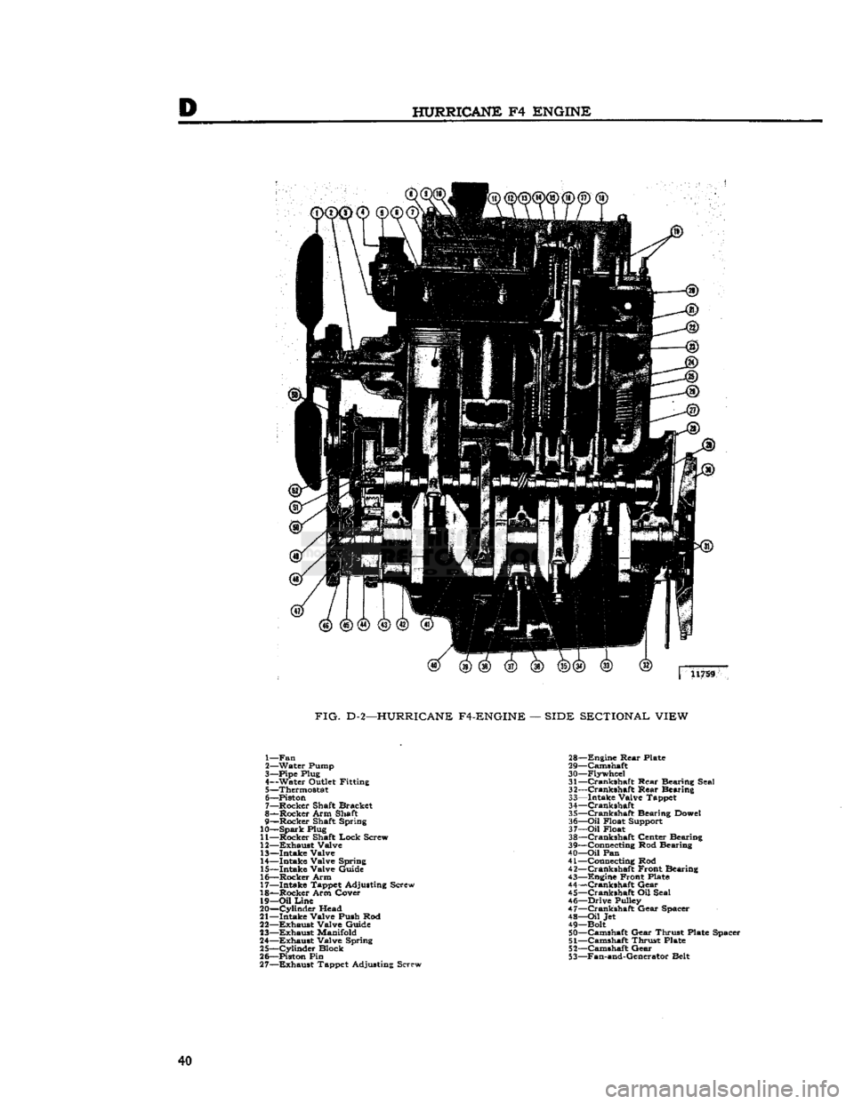
FIG.
D-2—HURRICANE F4-ENGINE
—
SIDE SECTIONAL VIEW
1— Fan
2— Water Pump
3— Pipe Plug
4— Water Outlet Fitting 5— Thermostat
6— Piston
7— Rocker Shaft Bracket
8— Rocker Arm Shaft
9— Rocker Shaft Spring
10—
Spark
Plug
11— Rocker Shaft Lock Screw
12—
Exhaust
Valve 13— Intake Valve
14— Intake Valve Spring
15— Intake Valve Guide
16— Rocker Arm
17— Intake Tappet Adjusting Screw
18— Rocker Arm Cover 19—
Oil
Line
20—
Cylinder
Head
21— Intake Valve Push Rod
22—
Exhaust
Valve Guide
23—
Exhaust
Manifold
24—
Exhaust
Valve Spring
25—
Cylinder
Block
26— Piston Pin 27—
Exhaust
Tappet Adjusting Screw 28—
Engine
Rear
Plate
29— Camshaft
30— Flywheel 31—
Crankshaft
Rear Bearing Seal
32—
Crankshaft
Rear Bearing
33— Intake Valve Tappet
34—
Crankshaft
35—
Crankshaft
Bearing Dowel
36—
Oil
Float Support
37—
Oil
Float
38—
Crankshaft
Center Bearing
39— Connecting Rod Bearing
40—
Oil
Pan
41— Connecting Rod
42—
Crankshaft
Front Bearing
43— Engine Front Plate
44—
Crankshaft
Gear
45—
Crankshaft
Oil Seal
46— Drive Pulley
47—
Crankshaft
Gear Spacer 48—
Oil
Jet
49— Bolt 50— Camshaft Gear Thrust Plate Spacer
51—
Camshaft Thrust Plate
52— Camshaft Gear
53— Fan-and-Generator Belt 40
Page 41 of 376
'Jeep*
UNIVERSAL SERIES
SERVICE
MANUAL
D
insulator
mountings attached to the frame side
rail
brackets. The
rear
of the engine-transmission
assembly is supported by a rubber insulator
mounting under the
rear
of the transmission on
the frame center cross member.
This
cross member
is bolted to the frame side
rails
so that it can be
dropped when removing the transmission or engine-
transmission
assembly. The rubber insulators allow
free side and vertical oscillation to effectively
neutralize
engine
vibration at the source.
The
rubber
insulator mountings should be inspected
for separation and deterioration by jacking the
power plant away from the frame, near the sup
ports. Vibration cannot be effectively absorbed by
separated or worn insulators. They should be re placed if faulty.
D-4.
Engine
Ground
Strap
To
be sure of an
effective
ground for the electrical
circuits,
a ground strap bridges the right front
engine
support to the chassis. The connections of this strap must be kept clean and tight for proper
operation of the electrical system.
D-5. ENGINE REMOVAL
Should
the
engine
require overhauling, it is neces
sary
to remove it from the vehicle. The following procedure covers removal of the
engine
only.
The
engine, transmission and transfer case may be
removed as a unit by removing (in addition to the following procedure) the radiator guard and the
access plates in the floor pan.
a.
Drain
the cooling system by opening the
drain
cocks at the
bottom
of the radiator and lower right
side of the cylinder block.
b.
Disconnect the battery at the positive terminal
to avoid the possibility of short
circuit.
c. Remove the air cleaner horn from the carburetor
and
disconnect the breather
hose
at the oil filler
pipe.
d.
Disconnect the carburetor choke and throttle controls by loosening the clamp
bolts
and set
screws.
e. Disconnect the fuel-tank-to-fuel-pump line at the fuel pump by unscrewing the connecting nut.
f- Plug the fuel line to prevent fuel leakage.
g. Remove the radiator and radiator grille support
rods.
h. Remove the upper and lower radiator
hoses
by
loosening the
hose
clamps and slipping the clamps
back
on the
hose.
If so equipped, remove the heater
hoses
(one to the water pump, one to the
rear
of
the cylinder head) in the same manner.
i.
Remove the four
bolts
from the fan hub and re
move
the fan hub and fan blades.
j.
Remove the four radiator attaching screws. Re
move
the radiator and shroud as one unit, k. Remove the starting motor cables. Remove the
starting
motor.
I.
Disconnect the wires from the alternator or
generator. Disconnect the ignition
primary
wire
at the ignition coil.
NOTE:
ON
ENGINES EQUIPPED WITH EX
HAUST
EMISSION CONTROL, REMOVE THE
AIR
PUMP,
AIR
DISTRIBUTION
MANI
FOLD,
AND
ANTI-BACKFIRE (DIVERTER)
VALVE.
SEE SECTION
Fl
FOR PROCEDURE.
m.
Disconnect the oil pressure and temperature
sending unit wires at the units.
n.
Disconnect the exhaust pipe at the exhaust
manifold by removing the stud nuts.
o.
Disconnect the
spark
plug cables at the plugs
and
remove the cable bracket from the rocker arm cover stud.
p.
Remove the rocker arm cover by removing the
attaching stud nuts.
q.
Attach a lifting bracket to the
engine
using
existing head bolt locations. Be sure the
bolts
selected
will
hold the
engine
with the weight
balanced.
Attach lifting bracket to a boom hoist,
or
other lifting device, and take up all slack,
r.
Remove the two nuts and
bolts
from each front
engine
support. Disconnect the
engine
ground strap.
Remove the
engine
supports.
Lower
the
engine
slightly to permit access to the two top
bolts
on
the flywheel housing.
s. Remove the
bolts
which attach the flywheel
housing to the engine.
t.
Pull
the
engine
forward, or
roll
the vehicle back
wards,
until the clutch clears the flywheel housing.
Lift
the
engine
from the vehicle.
D-6. ENGINE DISASSEMBLY
Engine
disassembly is presented in the sequence to be followed when the
engine
is to be completely
overhauled after removal from the vehicle. Some
of the operations of the procedure are also ap
plicable
separately with the
engine
in the vehicle,
provided
that wherever necessary the part of the
engine
to be worked on is first made accessible by
removal
of
engine
accessories or other parts.
When
the disassembly operations are performed
with
the
engine
out of the vehicle, it is assumed,
in
this procedure, that all of the accessories have been removed
prior
to starting the disassembly
and
the oil has been drained.
In
addition to the instructions covering operations
for disassembling the
engine
out of the vehicle,
special
instructions are given to cover different
operations required when disassembly is
done
with the
engine
installed.
During
disassembly operations, the
engine
should
be mounted in a suitable
engine
repair
stand. Where
practicable,
modify or adapt an existing repair
stand
as necessary to accommodate the engine. If
an
engine
repair stand is not used, take care to
perform
disassembly operations in a manner that
will
protect personnel against an accident and the
engine
and its parts against damage.
NOTE:
If the
engine
is being disassembled because
of possible valve failure, check the valve tappet
clearance
before disassembly. Improper valve
clearance
could be the possible cause of valve
failure,
indicating a need for more frequent valve
checks and adjustments. 41
Page 43 of 376
'Jeep*
UNIVERSAL SERIES SERVICE
MANUAL
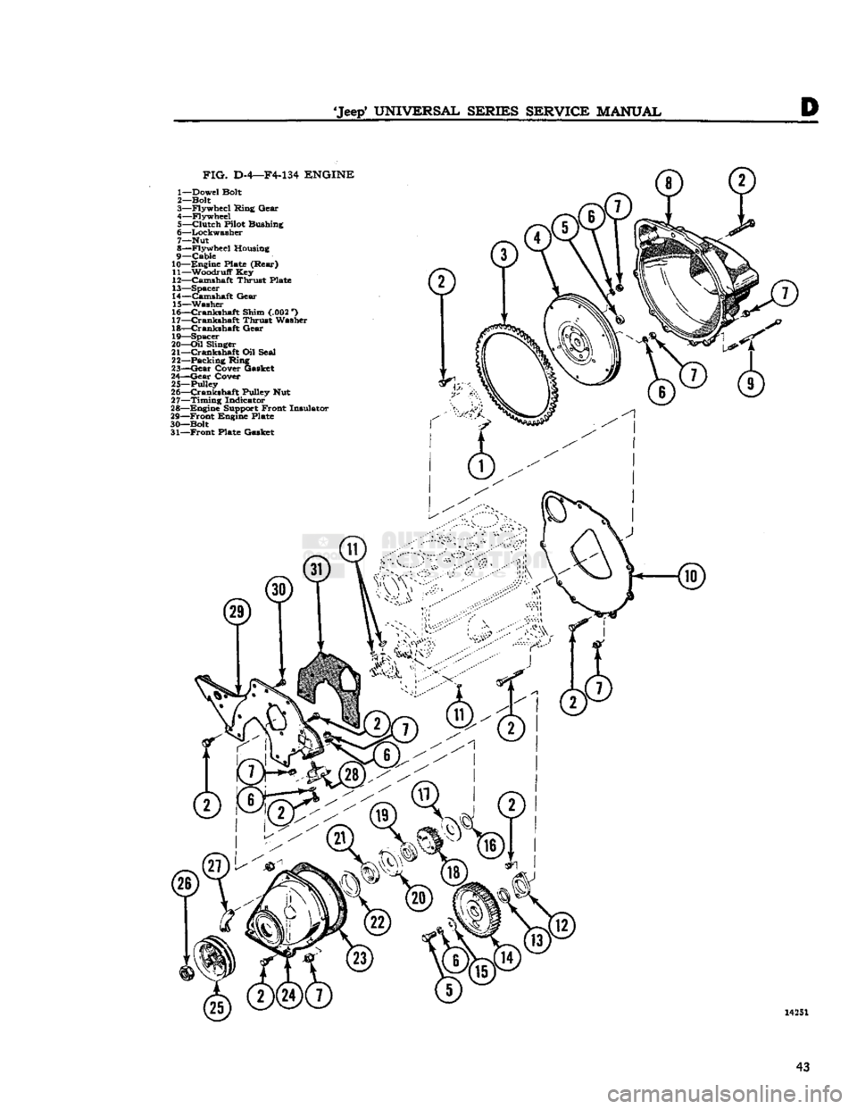
FIG.
D-4—F4-134
ENGINE
1— Dowel Bolt
2— Bolt
3— Flywheel Ring Gear
4— Flywheel 5—
Clutch
Pilot Bushing
6— Lockwasher
7— Nut
8— Flywheel Housing
9—
Cable
10— Engine Plate (Rear)
11— Woodruff Key
12— Camshaft Thrust Plate
13— Spacer
14— Camshaft Gear
15— Washer
16—
Crankshaft
Shim (.002 *)
17—
Crankshaft
Thrust Washer
18—
Crankshaft
Gear
19— Spacer
20—
Oil
Slinger
21—
Crankshaft
Oil Seal
22— Packing Ring
23—
Gear
Cover Gasket
24—
Gear
Cover
25—Pulley
26—
Crankshaft
Pulley Nut
27—
Timing
Indicator
28— Engine Support Front Insulator
29—
Front
Engine Plate
30— Bolt 31—
Front
Plate Gasket 14251
43
Page 44 of 376
D
HURRICANE
F4
ENGINE
Note:
Check
the condition of the rubber O-rings.
Defective O-rings could be the major cause of oil
leakage into cylinders. Always discard and replace
all
O-rings removed as only new O-rings should be installed at reassembly.
D-18.
Ream
Cylinder
Bore Ridges
To
prevent breaking the piston lands, the ridge
at the top of each cylinder bore must be removed
first.
To remove this ridge, use a cylinder ridge
reamer,
as shown in Fig. D-3 following the instruc
tions furnished by the reamer manufacturer. Use
care
not to cut below the top of the upper ring
travel
in the bore. Keep each piston top covered
with
an oil-soaked cloth to prevent cuttings from
falling
into the cylinder.
Note:
This
operation should be performed at this
time before the
engine
is rotated for the sequence
steps
following.
D-19.
Remove Oil Pan
Rotate the
engine
to the upside down position.
Remove the screws and lockwashers that attach
the oil pan to the cylinder block. Remove the oil
pan
and gasket.
Discard
the gasket.
D-20.
Remove Piston and Connecting
Rod
Assemblies
Remove the stamped locking nuts from the lower
end of each connecting rod bearing bolt. Remove
the connecting rod nuts. Remove the bearing cap evenly. Push the connecting rod and piston as
sembly out of the cylinder block with the handle end of a hammer until the piston rings are free from
the cylinder bore. Remove the piston and connecting rod assembly
from
the top of the cylinder block. Reassemble the
connecting rod bearing cap with the bearings in
place in the rod from which it was removed. Rotate
the crankshaft and follow the same procedure until
all
the piston and connecting rod assemblies are
removed.
Pistons and connecting rod assemblies may be removed for repair with the
engine
in the vehicle after draining the cooling system, removing the
oil
pan and the cylinder head, and reaming the ridges as previously described.
D-21.
Remove
Timing
Gear
Cover
Remove the bolts, nuts, and lockwashers, that at
tach
the timing gear cover to the engine. Remove
the cover, timing pointer, and cover gasket.
Dis
card
the gasket. Remove the crankshaft oil seal
from
the timing gear cover and discard the seal. Remove the oil slinger and spacer from the
crank
shaft.
D-22.
Remove
Timing
Gears
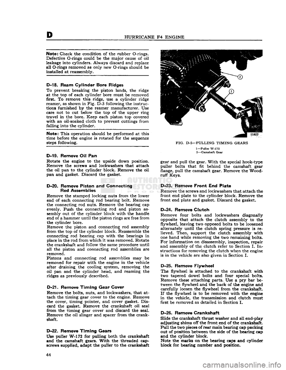
Use puller W-172 for pulling both the crankshaft
and
the camshaft gears.
With
the threaded cap-
screws supplied, adapt the puller to the crankshaft
FIG.
D-5—PULLING TIMING GEARS
1—
Puller
W-172 2—
Camshaft
Gear
gear and
pull
the gear.
With
the special hook-type
puller
bolts
that fit behind the camshaft gear
flange,
pull
the camshaft gear. Remove the Wood
ruff
Keys.
D-23.
Remove
Front
End Plate
Remove the screws and lockwashers that attach the
front end plate to the cylinder block. Remove the
front end plate and gasket.
Discard
the gasket.
D-24. Remove
Clutch
Remove four
bolts
and lockwashers diagonally
opposite
that attach the clutch assembly to the
flywheel, leaving two
opposed
bolts
to be
loosened
alternately until the clutch spring pressure is re
lieved.
Then,
support the clutch assembly with
one hand while removing the two remaining bolts.
For
information on disassembly, inspection, repair
and
assembly of the clutch refer to Section I. In
structions for removing the clutch when the
engine
is in the vehicle are also given in Section I.
D-25.
Remove Flywheel
The
flywheel is attached to the crankshaft with two tapered dowel
bolts
and four special bolts.
Remove
these
attaching parts. Use a pry bar be tween the flywheel and the back of the
engine
and
carefully
loosen
the flywheel from the crankshaft.
If
the flywheel is to be removed with the
engine
in
the vehicle, the transmission and clutch must
first be removed as detailed in Section I.
D-26.
Remove
Crankshaft
Slide
the crankshaft thrust washer and all end-play
adjusting
shims off the front end of the crankshaft.
Pull
the two pieces of
rear
main bearing cap packing out of position
between
the side of the bearing cap
and
the cylinder block.
Note
the marks on the bearing caps and cylinder
block for bearing number and position. 44
Page 45 of 376
'Jeep'
UNIVERSAL SERIES SERVICE
MANUAL
D
Remove the screws and lockwashers that attach
the main bearing caps to the cylinder block. Use
a
lifting bar beneath the ends of each bearing cap.
Be
careful not to exert too much pressure to cause
damage to the cap or
dowels
and pry the caps free.
CAUTION:
If main bearing caps are not removed
carefully
by raising both sides of each cap evenly
until
free of the dowels, the
dowels
may be bent.
A
bent main bearing cap dowel can cause misalign ment of the cap and resultant
rapid
bearing wear
necessitating replacement. Therefore, remove each
main
bearing cap carefully. If there is reason to
believe any of the
dowels
have been bent during
the bearing cap removal, remove them and install
new
dowels
as detailed in Par. D-34c.
Remove the upper
half
of the
rear
main bearing
oil
seal from the cylinder block and the lower
half
from
the oil seal
groove
in the
rear
main bearing
cap.
Install
the main bearing caps and bearings on
the cylinder block in their original positions.
Note;
Removal of the crankshaft may be ac
complished only with the
engine
out of the vehicle.
D-27.
Remove
Exhaust
Valves and Springs
Access to the valve chamber is obtained by re moving the attaching parts and the valve spring
cover and gasket from the cylinder block. Use cloths
to block off the three
holes
in the exhaust valve
chamber to prevent the valve retaining locks falling
into the crankcase, should they be accidentally dropped.
With
a valve
/
spring compressor, compress the valve springs on
those
valves which are in the
closed position (valve seated against cylinder
block).
Remove the exhaust valve spring retainer
locks,
the exhaust valve spring retainer, and the exhaust valve spring. Close the other valves by
rotating the camshaft and repeat the above opera
tion for the other valves in the same manner.
Lift
out all the exhaust valves and tag or place them in
a
rack
to indicate the location where each was removed from the cylinder block. If a valve sticks in
the guide and cannot be easily lifted out,
pull
the valve upward as far as possible and remove the
spring.
Lower
the valve and remove any carbon
deposits
from the valve stem.
This
will
permit re moval of the valve.
For
intake valve and spring removal, see
Par.
D-l7.
D-28.
Remove Camshaft
a.
Push the intake and exhaust valve tappets into the cylinder block as far as possible so the ends of
the tappets are not in contact with the camshaft. b. Secure each tappet in the raised position by in
stalling a common clip-type clothes pin on the
shank
of each tappet or tie them up in the valve
chamber.
c. Remove the camshaft thrust plate attaching
screws.
Remove the camshaft thrust plate and
spacer.
d.
Pull
the camshaft forward out of the cylinder
block using care to prevent damage to the cam
shaft bearing surfaces.
D-29.
Remove Valve Tappets
Remove the intake and exhaust valve tappets from
the
bottom
or crankshaft side of the cylinder block
after the camshaft has been removed. Tag each
tappet or place them in a marked
rack
so they may be reassembled in their original positions.
D-30.
Remove Oil
Gallery
Plugs
Remove the plug at each end of the oil gallery in the cylinder block.
This
operation is only applicable
when the
engine
is out of the vehicle and
will
allow access to the oil gallery so it may be cleaned.
D-31. ENGINE INSPECTION
AND
REPAIR
The
inspection and repair procedures detailed here
in
are recommended to be followed when a com
plete
engine
overhaul is to be made with the
engine
out of the vehicle. These instructions can generally be applied individually with the
engine
in the
vehicle. Wherever the procedure differs due to
the
engine
being in the vehicle, the necessary
special
instructions are provided. Inspection and
repair
instructions are included to cover the
cylinder
block, cylinder head, crankshaft and bearings, connecting rods and bearings, oil pump, valves and tappets, pistons and rings, flywheel,
timing gears, and the camshaft and bearings. In addition, fitting operations for
these
engine
com
ponents
are included.
Important:
Before the inspection and repair pro
cedures listed below are begun, the
engine
serial
number must be checked for the presence of
code
letters denoting undersize bearings or oversize
pistons. Refer to Par. D-2.
D-32.
Cylinder
Block
The
cylinder block must be thoroughly cleaned, inspected and repaired as detailed in the following
paragraphs.
D-33.
Cleaning
The
cylinder block may be steam cleaned or cleaned
with
a suitable solvent. A scraper is recommended
to remove
hard
deposits, except on highly finished surfaces. Special attention must be directed to the
cleaning of the oil passages, valve chamber,
crank
case, and cylinder walls to remove all sludge,
dirt
and
carbon deposits. After cleaning, use air pressure to dry the block thoroughly.
D-34. Inspection
Examine
the cylinder block for minute cracks and
fractures.
Rusted valve springs or evidence of rust
in
the valve chamber or the cylinder walls is a
good
indication of a possible
crack
in the block,
a.
Examine all machined surfaces of the cylinder block for
burrs
and scores.
Check
for cylinder block
distortion by placing a straight
edge
along the
length of the cylinder head surface of the block.
With
a feeler
gauge,
check for clearance
between
the straight
edge
and the block, particularly be
tween adjacent cylinders. Maximum permissible
out of line for service is .010"
[0,254
mm.] over the
full
length of the block. 45
Page 54 of 376
D
HURRICANE
F4
ENGINE
against the hub of the crankshaft pulley.
Timing
gears are accessible for inspection or replacement
with
the
engine
installed in the vehicle after re moving the radiator, belt drive pulley, and timing
cover.
Should
it be necessary to replace the timing gears, attention must be given to the end float of both
the camshaft and crankshaft and to the running
clearance
of both gears. It is also advisable to
check
both the oil jet and oil passage to the
crank
shaft front bearing to be sure that they are clear.
D-55.
Inspection and
Repair
Check
the general condition of both gears and
inspect for evidence of excessive wear. Replace
excessively worn or damaged gears. Inspect the
cover and replace if bent or damaged. It is recom mended that the crankshaft oil seal in the cover
be replaced when the cover is removed to ensure a
good
seal around the crankshaft. To replace this
seal
with the
engine
in the vehicle
requires
removing
the radiator and water pump.
D-56.
Valves, Springs, and Guides
The
exhaust valves seat on the top of the cylinder
block
with the
stems
extending down through
replaceable valve guides. The exhaust valves are actuated by the camshaft through exhaust valve
tappets. The exhaust valve springs are assembled
and
locked on the lower end of the exhaust valve
stems. The retaining locks are the split type, which
fit in a recess on the valve
stems
and into the taper
in
the valve spring retainers.
Adjustment
of exhaust valves is by means of the
adjusting
screw threaded into the upper end of the
exhaust valve tappets. An exhaust valve rotator used as a valve spring retainer is installed on the
lower end of the exhaust valve.
This
valve rotator,
known
as "Roto Cap", is a spring-loaded
ball
bearing
device. On each lift, or opening stroke of
a
valve, the rotator
gives
the valve a slight positive
clockwise rotation.
The
intake valves operate in valve
guides
in the
cylinder
head and are actuated by rocker arms.
The
rocker arms are actuated by valve push rods
and
the intake valve tappets. The intake valve
springs,
the intake valve spring retainers, and the
intake
valve spring retainer locks make up the
remainder
of the valve operating parts. An intake
valve spring retainer oil seal which encircles the
upper
end of the intake valve
between
the valve
locks and the upper end of the valve spring re
tainer,
controls the passage of oil along the valve
stem and guide.
Note:
When
engine
trouble indicates defective
valves as a possible source of trouble, also check
all
vacuum line connections for possible leaks.
D-57.
Inspection of Valves, Springs,
and
Guides
Clean
the valves on a wire wheel, making sure that
all
carbon is removed from the top and the under
side of the heads and that all gum and varnish
deposits
are removed from the stems.
Polish
the valve
stems
with steel wool or crocus
cloth.
Visually
inspect all valves for warpage,
cracks,
or excessive burning and discard if one of
these
conditions exists. Replace any worn, pitted,
or
corroded valves that cannot be cleaned with a
wire
brush.
Replace any valves when
seats
are pitted, burned, or corroded so badly that they
cannot be cleaned up with a light refacing on a valve refacing machine.
Replace
valves with marks of scoring or abrasion visible on the stem. Replace any valves with bent
stems
which
will
be apparent when the valve is
mounted in the valve refacing machine.
Note:
Use only hard-face exhaust valves for
replacement.
Examine
the
stems
of valves which employ the
ball
bearing rotators.
Wear
marks around the
cir
cumference of the
stems
indicates that the valve is
rotating satisfactorily.
Vertical
heavy pressure
areas
indicate that the valve is not rotating and the valve spring retainer (Roto
Cap)
should be replaced
if
at fault.
Check
the diameter of the valve stem at two or three places along the length of the stem
with
a micrometer. The intake valve stem diameter is .3733" to .3738" [9,482 a
9,495
mm.]. The
exhaust valve stem diameter is .371" to .372"
[9,423
a
9,449
mm.].
Note:
Exhaust
and intake valve springs are
similar
in appearance. They must not be inter
changed as they have different spring
charac
teristics.
Wash
the valve springs thoroughly in solvent.
Visually
examine the springs and replace any that
are
deformed or obviously damaged. Examine for
corrosion
from moisture or acid etching which might
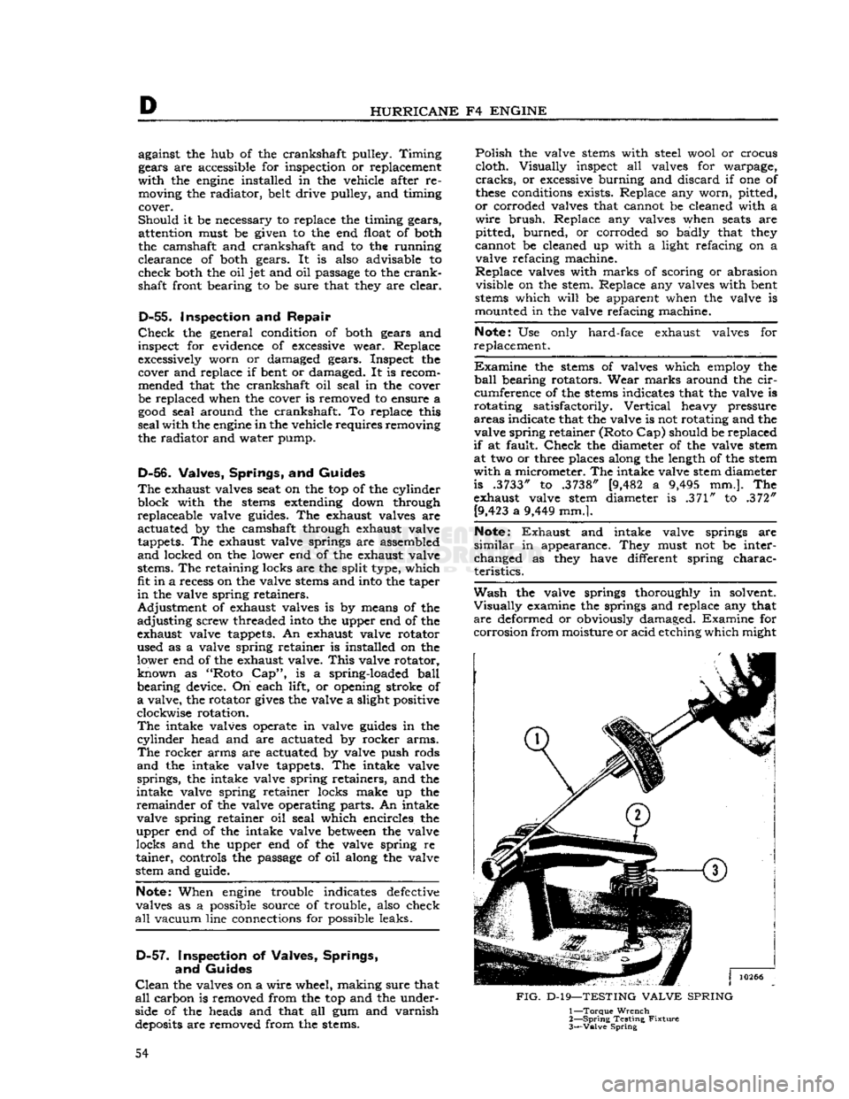
FIG.
D-19—TESTING
VALVE
SPRING
1—
Torque
Wrench
2—
Spring
Testing
Fixture
3—
Valve
Spring
54
Page 59 of 376
'Jeep*
UNIVERSAL SERIES SERVICE
MANUAL
D
10262
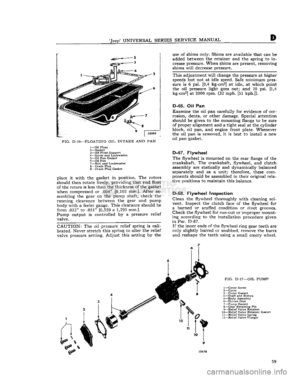
FIG.
D-26—FLOATING OIL INTAKE AND PAN 1—
Oil
Float
2—
Gasket
3—
Oil
Float Support
4—
Screw and Lockwasher 5—
Oil
Pan Gasket
6—
Oil
Pan 7—
Bolt
and Lockwasher
8—
Drain
Plug
9—
Drain
Plug Gasket
place it with the gasket in position. The rotors
should then rotate freely, providing that end float of the rotors is
less
than the thickness of the gasket
when compressed or .004" [0,102 mm.]. After as
sembling the gear on the pump shaft, check the
running
clearance
between
the gear and pump body with a feeler
gauge.
This
clearance should be
from
.022" to .051" [0,559 a 1,295 mm.].
Pump
output is controlled by a pressure relief valve.
CAUTION:
The oil pressure relief spring is
cali
brated.
Never stretch this spring to alter the relief valve pressure setting. Adjust this setting by the use of shims only. Shims are available that can be
added
between
the retainer and the spring to in
crease pressure. When shims are present, removing
shims
will
decrease pressure.
This
adjustment
will
change the pressure at higher
speeds
but not at idle speed. Safe minimum pres
sure
is 6 psi. [0,4 kg-cm2] at idle, at which point
the oil pressure light
goes
out; and 20 psi. [1,4
kg-cm2] at
2000
rpm. (32 mph. [51 kph.]).
D-66.
Oil Pan
Examine
the oil pan carefully for evidence of cor
rosion,
dents, or other damage. Special attention
should be given to the mounting flange to be sure of proper alignment and a tight seal at the cylinder
block, oil pan, and
engine
front plate. Whenever
the oil pan is removed, it is
best
to install a new
oil
pan gasket.
D-67.
Flywheel
The
flywheel is mounted on the
rear
flange of the
crankshaft.
The crankshaft, flywheel, and clutch
assembly are statically and dynamically balanced
separately and as a unit; therefore,
these
com
ponents
should be assembled in their original
rela
tive positions to maintain this balance.
D-68.
Flywheel Inspection
Clean
the flywheel thoroughly with cleaning sol vent. Inspect the clutch face of the flywheel for
a
burned or scuffed condition or rivet grooves.
Check
the flywheel for run-out or improper mount
ing according to the installation procedure given
in Par.
D-87.
If
the inner ends of the flywheel ring gear
teeth
are
only slightly burred cr snubbed, remove the burrs
and
reshape the
teeth
using a small emery wheel. 59
Page 60 of 376
HURRICANE
F4
ENGINE
FIG.
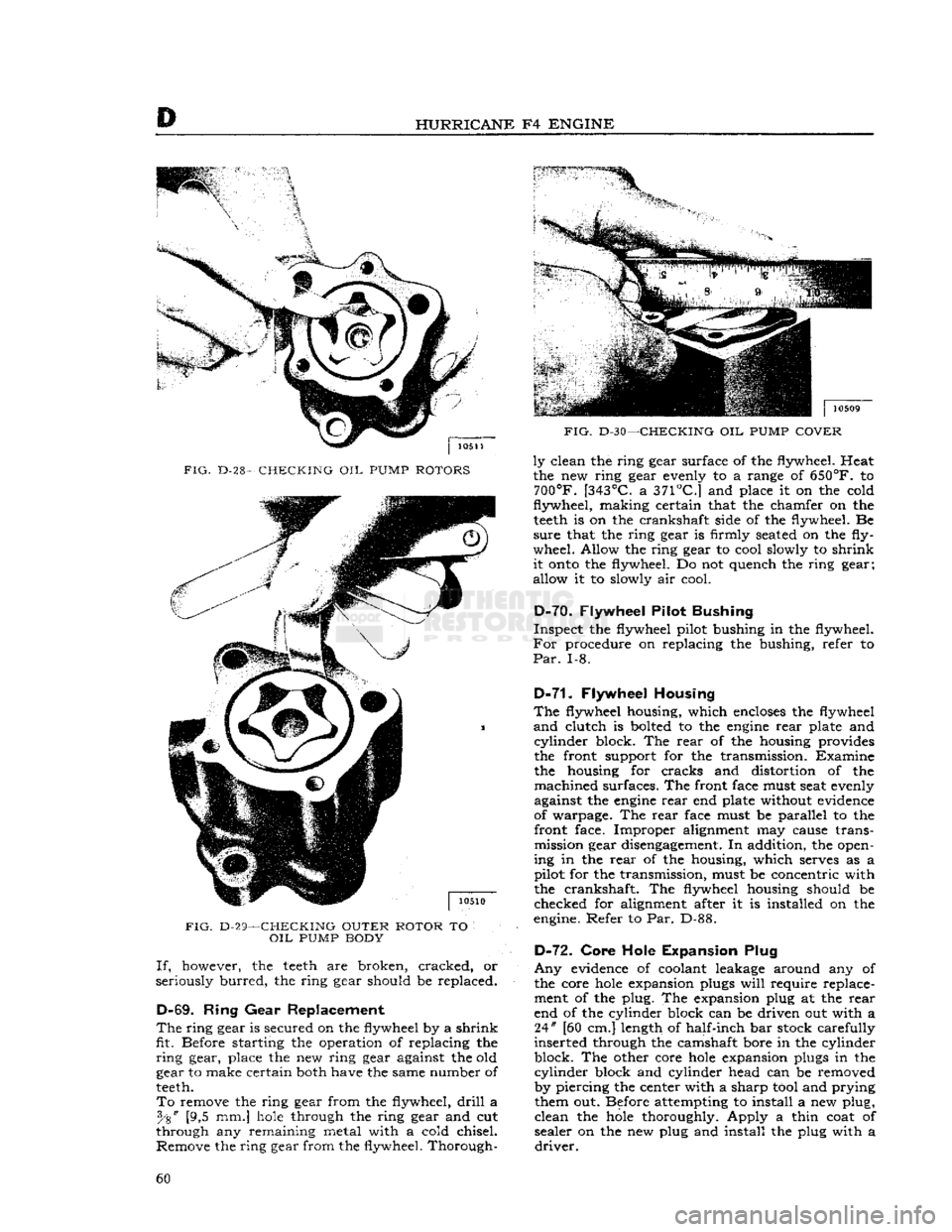
D-28-
CHECKING
OIL
PUMP
ROTORS
FIG.
D-29—CHECKING OUTER ROTOR
TO
OIL
PUMP
BODY If,
however, the
teeth
are broken, cracked, or
seriously
burred,
the ring gear should be replaced.
D-69.
Ring
Gear
Replacement
The
ring
gear
is secured on the flywheel by a
shrink
fit. Before starting the operation of replacing the
ring
gear, place the new ring gear against the old
gear to make certain both have the same number of
teeth.
To
remove the ring gear from the flywheel,
drill
a [9,5 mm.]
hole
through the ring gear and cut
through any remaining metal with a cold chisel. Remove the ring gear from the flywheel. Thorough-
FIG.
D-30—CHECKING
OIL
PUMP
COVER
ly
clean the ring gear surface of the flywheel. Heat
the new ring gear evenly to a range of
650°F.
to
700°F.
[343°C.
a
371°C.]
and place it on the cold
flywheel,
making
certain that the chamfer on the
teeth
is on the crankshaft side of the flywheel. Be
sure
that the ring gear is firmly seated on the fly
wheel. Allow the ring gear to cool slowly to
shrink
it
onto
the flywheel. Do not quench the ring gear;
allow it to slowly air cool.
D-7Q.
Flywheel Pilot Bushing
Inspect
the flywheel pilot bushing in the flywheel.
For
procedure on replacing the bushing, refer to
Par.
1-8.
D-71.
Flywheel Housing
The
flywheel housing, which
encloses
the flywheel
and
clutch is bolted to the
engine
rear
plate and
cylinder
block. The
rear
of the housing provides
the front support for the transmission. Examine the housing for cracks and distortion of the
machined
surfaces. The front face must seat evenly
against the
engine
rear
end plate without evidence
of warpage. The
rear
face must be parallel to the front face. Improper alignment may cause transmission gear disengagement. In addition, the open
ing in the
rear
of the housing, which serves as a
pilot for the transmission, must be concentric with the crankshaft. The flywheel housing should be
checked for alignment after it is installed on the
engine. Refer to Par. D-88.
D-72.
Core Hole Expansion Plug
Any
evidence of coolant leakage around any of
the core
hole
expansion plugs
will
require replace ment of the plug. The expansion plug at the
rear
end of the cylinder block can be driven out with a 24" [60 cm.] length of half-inch bar stock carefully
inserted through the camshaft bore in the cylinder
block. The other core
hole
expansion plugs in the
cylinder
block and cylinder head can be removed
by piercing the center with a sharp tool and prying them out. Before attempting to install a new plug,
clean
the
hole
thoroughly. Apply a thin coat of
sealer on the new plug and install the plug with a
driver.
60
Page 64 of 376
D
HURRICANE
F4
ENGINE
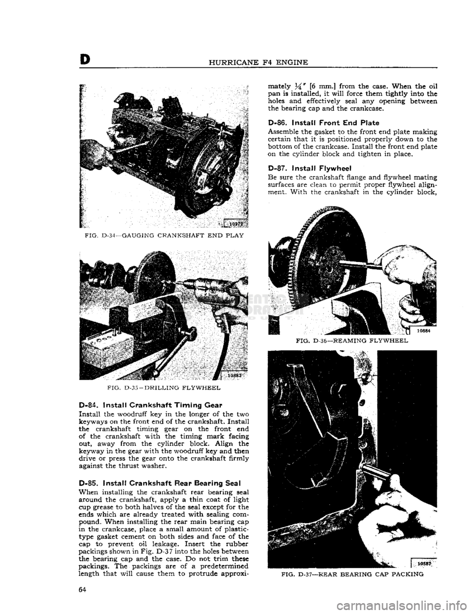
FIG.
D-34—GAUGING
CRANKSHAFT
END
PLAY
FIG.
D-35
—
DRILLING FLYWHEEL
D-84.
Install
Crankshaft Timing
Gear
Install
the woodruff key in the longer of the two keyways on the front end of the crankshaft.
Install
the crankshaft timing gear on the front end of the crankshaft with the timing
mark
facing out, away from the cylinder block. Align the
keyway in the gear with the woodruff key and then
drive
or press the gear
onto
the crankshaft firmly against the thrust washer.
D-85.
Install
Crankshaft
Rear
Bearing Seal
When
installing the crankshaft
rear
bearing seal
around
the crankshaft, apply a thin coat of light cup grease to both halves of the seal except for the
ends which are already treated with sealing com pound. When installing the
rear
main bearing cap
in
the crankcase, place a small amount of plastic- type gasket cement on both sides and face of the
cap to prevent oil leakage. Insert the rubber
packings shown in
Fig. D-3
7
into the
holes
between
the bearing cap and the case. Do not trim
these
packings. The packings are of a predetermined
length that
will
cause them to protrude approxi mately 34* [6 mm.] from the case. When the oil
pan
is installed, it
will
force them tightly into the
holes
and effectively seal any opening
between
the bearing cap and the crankcase.
D-86.
Install
Front
End Plate
Assemble the gasket to the front end plate making
certain
that it is positioned properly down to the
bottom
of the crankcase.
Install
the front end plate
on the cylinder block and tighten in place.
D-87.
Install
Flywheel
Be
sure the crankshaft flange and flywheel mating
surfaces are clean to permit proper flywheel align ment. With the crankshaft in the cylinder block,
FIG.
D-36—
REAMING FLYWHEEL
FIG.
D-37—REAR
BEARING
CAP
PACKING
64