engine JEEP CJ 1953 Owner's Guide
[x] Cancel search | Manufacturer: JEEP, Model Year: 1953, Model line: CJ, Model: JEEP CJ 1953Pages: 376, PDF Size: 19.96 MB
Page 31 of 376
'Jeep'
UNIVERSAL
SERIES
SERVICE
MANUAL
C
FIG.
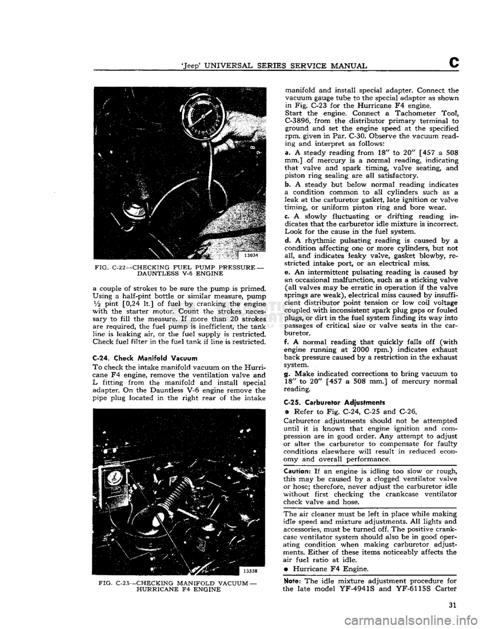
C-22—-CHECKING
FUEL
PUMP
PRESSURE
—
DAUNTLESS
V-6
ENGINE a
couple of strokes to be sure the pump is primed.
Using
a half-pint
bottle
or similar measure, pump
Vi
pint [0,24 It] of fuel by cranking the
engine
with
the starter motor. Count the strokes neces
sary
to
fill
the measure. If more than 20 strokes
are
required, the fuel pump is inefficient, the tank
line is leaking air, or the fuel supply is restricted.
Check
fuel filter in the fuel tank if line is restricted.
C-24.
Check Manifold Vacuum
To
check the intake manifold vacuum on the
Hurri
cane F4 engine, remove the ventilation valve and
L
fitting from the manifold and install special adapter. On the Dauntless V-6
engine
remove the
pipe plug located in the right
rear
of the intake
FIG.
C-23—CHECKING MANIFOLD VACUUM
—
HURRICANE
F4
ENGINE
manifold and install special adapter. Connect the
vacuum
gauge
tube to the special adapter as shown
in
Fig. C-23 for the
Hurricane
F4 engine.
Start
the engine. Connect a Tachometer
Tool,
C-3896,
from the distributor
primary
terminal to ground and set the
engine
speed at the specified
rpm.
given in Par. C-30. Observe the vacuum
read
ing and interpret as follows:
a.
A steady reading from 18" to 20" [457 a 508
mm.] of mercury is a normal reading, indicating
that valve and
spark
timing, valve seating, and
piston ring sealing are all satisfactory.
b. A steady but below normal reading indicates
a
condition common to all cylinders such as a
leak
at the carburetor gasket, late ignition or valve
timing, or uniform piston ring and bore wear.
c.
A slowly fluctuating or drifting reading in dicates that the carburetor idle mixture is incorrect
Look
for the cause in the fuel system.
d.
A rhythmic pulsating reading is caused by a
condition affecting one or more cylinders, but not
all,
and indicates leaky valve, gasket blowby, re
stricted intake port, or an electrical miss.
e. An intermittent pulsating reading is caused by
an
occasional malfunction, such as a sticking valve
(all
valves may be
erratic
in operation if the valve
springs are weak), electrical miss caused by insuffi
cient distributor point tension or low coil
voltage
coupled with inconsistent
spark
plug
gaps
or fouled
plugs, or
dirt
in the fuel system finding its way into
passages of
critical
size or valve
seats
in the
car
buretor.
f.
A normal reading that quickly falls off (with
engine
running at
2000
rpm.) indicates exhaust
back
pressure caused by a restriction in the exhaust
system.
g.
Make indicated corrections to bring vacuum to 18" to 20" [457 a 508 mm.] of mercury normal
reading.
C-25.
Carburetor Adjustments
•
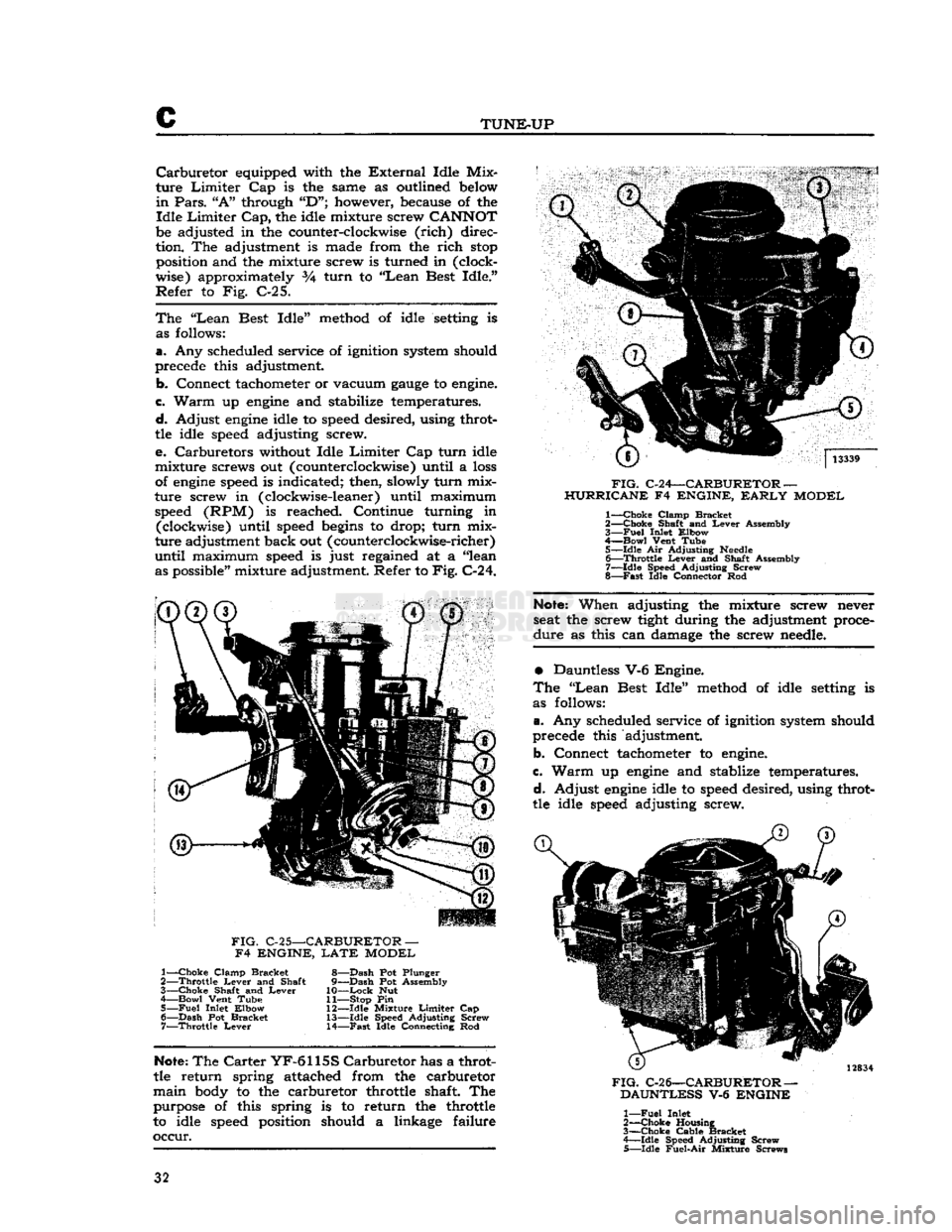
Refer to Fig. C-24, C-25 and C-26.
Carburetor
adjustments should not be attempted
until
it is known that
engine
ignition and com
pression are in
good
order. Any attempt to adjust
or
alter the carburetor to compensate for faulty conditions elsewhere
will
result in reduced econ
omy and overall performance.
Caution:
If an
engine
is idling too slow or rough,
this may be caused by a
clogged
ventilator valve
or
hose;
therefore, never adjust the carburetor idle
without first checking the crankcase ventilator
check valve and
hose.
The
air cleaner must be left in place while making
idle speed and mixture adjustments. All lights and accessories, must be turned off. The positive
crank
case ventilator system should also be in
good
oper
ating condition when making carburetor adjust ments.
Either
of
these
items noticeably affects the
air
fuel ratio at idle.
•
Hurricane
F4 Engine.
Note:
The idle mixture adjustment procedure for
the late model
YF-4941S
and
YF-6115S
Carter
31
Page 32 of 376
c
TUNE-UP
Carburetor
equipped with the
External
Idle Mix
ture
Limiter
Cap is the same as outlined below
in
Pars.
"A"
through
"D";
however, because of the
Idle
Limiter
Cap,
the idle mixture screw
CANNOT
be adjusted in the counter-clockwise
(rich)
direc
tion. The adjustment is made from the
rich
stop
position and the mixture screw is turned in (clock
wise) approximately 3A turn to
"Lean
Best Idle."
Refer
to Fig. C-25.
The
"Lean
Best Idle" method of idle setting is as follows:
a.
Any scheduled service of ignition system should
precede this adjustment.
b.
Connect tachometer or vacuum
gauge
to engine.
c.
Warm
up
engine
and stabilize temperatures.
d.
Adjust
engine
idle to speed desired, using throt
tle idle speed adjusting screw.
e.
Carburetors without Idle
Limiter
Cap turn idle
mixture screws out (counterclockwise) until a
loss
of
engine
speed is indicated; then, slowly turn mix
ture screw in (clockwise-leaner) until maximum speed (RPM) is reached. Continue turning in (clockwise) until speed
begins
to drop; turn mix
ture adjustment back out (counterclockwise-richer)
until
maximum speed is just regained at a "lean as possible" mixture adjustment. Refer to
Fig.
C-24.
FIG.
C-24—CARBURETOR —
HURRICANE F4 ENGINE,
EARLY
MODEL 1—
Choke
Clamp Bracket
2—
Choke
Shaft and
Lever
Assembly
3—
Fuel
Inlet Elbow
4—
Bowl
Vent Tube 5— idle Air Adjusting
Needle
6—
Throttle
Lever
and Shalt Assembly
7—
Idle
Speed Adjusting Screw
8—
Fast
Idle Connector Rod
FIG.
C-25—CARBURETOR —
F4 ENGINE,
LATE
MODEL 1—
Choke
Clamp Bracket
2—
Throttle
Lever
and Shaft
3—
Choke
Shaft and
Lever
4 Bowl Vent Tube 5—
Fuel
Inlet Elbow 6—
Dash
Pot Bracket 7—
Throttle
Lever
8—
Dash
Pot Plunger
9—
Dash
Pot Assembly
10—
Lock
Nut
11— Stop Pin
12—
Idle
Mixture
Limiter
Cap 13—
Idle
Speed Adjusting Screw
14—
Fast
Idle Connecting Rod
Note:
When adjusting the mixture screw never
seat the screw tight during the adjustment proce
dure
as this can damage the screw needle.
•
Dauntless V-6 Engine.
The
"Lean
Best Idle" method of idle setting is
as follows:
a.
Any scheduled service of ignition system should
precede this adjustment.
b. Connect tachometer to engine.
c.
Warm
up
engine
and stablize temperatures.
d.
Adjust
engine
idle to speed desired, using throt
tle idle speed adjusting screw.
Note:
The
Carter
YF-6115S
Carburetor
has a throt
tle return spring attached from the carburetor
main
body to the carburetor throttle shaft The purpose of this spring is to return the throttle
to idle speed position should a linkage failure
occur.
FIG.
C-26—CARBURETOR —
DAUNTLESS V-6 ENGINE 1—
Fuel
Inlet
2—
-Choke
Housing
3—
Choke
Cable Bracket
4—
Idle
Speed Adjusting Screw
5—
Idle
Fuel-Air
Mixture Screws 32
Page 33 of 376
'Jeep*
UNIVERSAL
SERIES
SERVICE
MANUAL
C
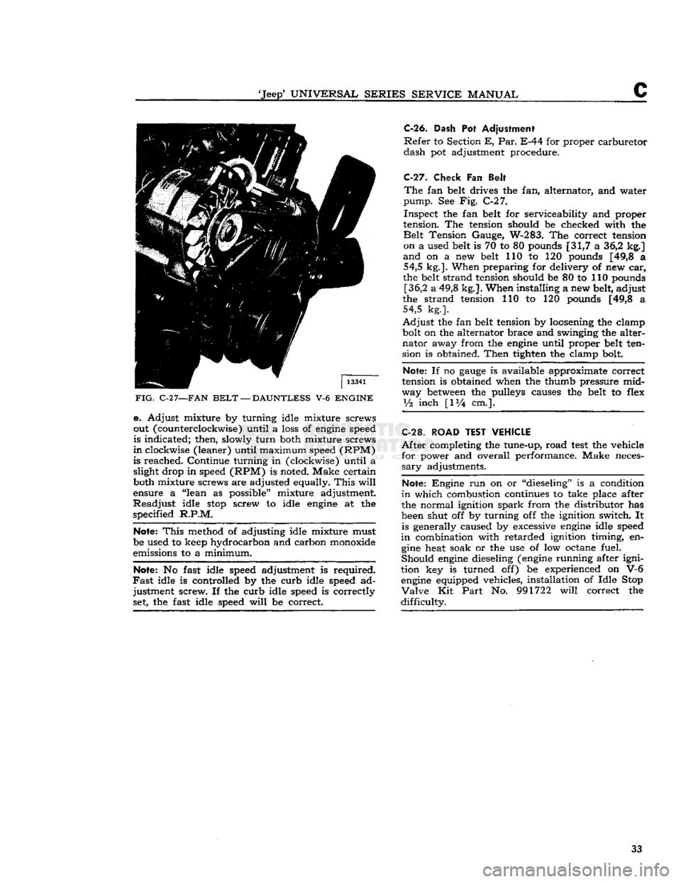
FIG.
C-2
7—FAN
BELT
—
DAUNTLESS
V-6
ENGINE
e. Adjust mixture by turning idle mixture screws
out (counterclockwise) until a loss of engine speed
is indicated; then, slowly
turn
both mixture screws
in
clockwise (leaner) until maximum speed (RPM)
is reached. Continue turning in (clockwise) until a slight drop in speed (RPM) is noted. Make certain
both mixture screws are adjusted equally.
This
will
ensure a "lean as possible" mixture adjustment.
Readjust
idle
stop
screw to idle engine at the
specified
R.P.M.
Note:
This
method of adjusting idle mixture must
be used to keep hydrocarbon and carbon monoxide
emissions to a minimum.
Note:
No fast idle speed adjustment is required.
Fast
idle is controlled by the curb idle speed ad justment screw. If the curb idle speed is correctly set, the fast idle speed
will
be correct.
C-26.
Dash
Pot
Adjustment
Refer
to Section
E, Par.
E-44 for proper carburetor
dash
pot adjustment procedure.
C-27.
Check
Fan
Belt
The
fan belt drives the fan, alternator, and water
pump.
See Fig. C-27.
Inspect
the fan belt for serviceability and proper
tension. The tension should be checked with the
Belt
Tension Gauge, W-283. The correct tension on a used belt is 70 to 80 pounds [31,7 a 36,2 kg.]
and
on a new belt 110 to 120 pounds [49,8 a 54,5 kg.]. When preparing for delivery of new car,
the belt strand tension should be 80 to 110 pounds [36,2 a 49,8 kg.]. When installing a new belt, adjust
the strand tension 110 to 120 pounds [49,8 a 54,5 kg.].
Adjust
the fan belt tension by loosening the clamp
bolt on the alternator brace and swinging the alter
nator
away from the engine until proper belt ten
sion is obtained.
Then
tighten the clamp bolt.
Note:
If no
gauge
is available approximate correct
tension is obtained when the thumb pressure mid
way between the pulleys causes the belt to flex
y%
inch
[IV4
cm.].
C-28.
ROAD TEST VEHICLE
After
completing the tune-up, road
test
the vehicle for power and overall performance. Make neces
sary
adjustments.
Note:
Engine run on or "dieseling" is a condition
in
which combustion continues to take place after
the normal ignition
spark
from the distributor has
been shut off by turning off the ignition switch. It is generally caused by excessive engine idle speed
in
combination with retarded ignition timing, en gine heat soak or the use of low octane fuel.
Should
engine dieseling (engine running after igni
tion key is turned off) be experienced on V-6 engine equipped vehicles, installation of Idle Stop
Valve
Kit
Part
No. 991722
will
correct the
difficulty.
33
Page 34 of 376
TUNE-UP
C-29.
SERVICE
DIAGNOSIS
POOR
FUEL ECONOMY Ignition Timing Slow or Spark Advance Stuck
Carburetor
Float High
Accelerator Pump Not Properly Adjusted High Fuel Pump Pressure
Fuel
Leakage
Leaky
Fuel Pump Diaphragm Loose Engine Mounting Causing High Fuel Level in Carburetor
Low
Compression
Valves Sticking
Spark
Plugs Bad
Spark
Plug Cables Bad
Weak
Coil
or Condenser Improper Valve Tappet Clearance
Carburetor
Air Cleaner Dirty
High Oil Level in Air Cleaner Dragging Brakes
Front
Wheels Out of Alignment
Tires
Improperly Inflated Inaccurate Odometer
Faulty
Fuel Tank Cap
Clogged
Muffler or Bent Exhaust Pipe Sticking Exhaust Manifold Valve
LACK
OF POWER
Low
Compression Ignition System (Timing Late)
Improper Functioning Carburetor
or Fuel Pump
Fuel
Lines
Clogged
Air
Cleaner Restricted Engine Temperature High Improper Tappet Clearance
Sticking Valves
Valve Timing Late
Leaky
Gaskets
Muffler
Clogged
Bent Exhaust Pipe Sticking Exhaust Manifold Valve —
Dauntless V-6 Engine
LOW
COMPRESSION
Leaky
Valves Poor Piston Ring Seal Sticking Valves
Valve Spring Weak or Broken
Cylinder
Scored or Worn
Tappet Clearance Incorrect Piston Clearance too Large
Leaky
Cylinder Head Gasket
BURNED
VALVES AND SEATS Sticking Valves or too Loose in Guides
Improper Timing
Excessive Carbon Around Valve Head and Seat Overheating
Valve Spring Weak or Broken
Valve Tappet Sticking
Valve Tappet Clearance Incorrect
Clogged
Exhaust System
Defective
Valve
Lifter
— Hydraulic
VALVES
STICKING
Warped Valve Improper Tappet Clearance Carbonized or Scored Valve
Stems
Insufficient Clearance Valve Stem to Guide
Weak or Broken Valve Spring Valve Spring Cocked Contaminated Oil
OVERHEATING
Inoperative Cooling System
Theromstat Inoperative Improper Ignition Timing
Improper Valve Timing
Excessive Carbon Accumulation
Fan
Belt too Loose
Clogged
Muffler or Bent Exhaust Pipe
Oil
System Failure Scored or Leaky Piston Rings
Sticking Exhaust Manifold Valve — Dauntless V-6 Engine
POPPING-SPITTING-DETONATION
Improper Ignition Improper Carburetion
Excessive Carbon
Deposit
in
Combustion Chambers
Poor Valve Seating Sticking Valves
Broken Valve Spring Tappets Adjusted too Close
Spark
Plug Electrodes Burned
Water or Dirt in Fuel
Clogged
Lines Improper Valve Timing
Clogged
Fuel Filter Sticking Exhaust Manifold Valve —
Dauntless V-6 Engine
EXCESSIVE
OIL CONSUMPTION Piston Rings Stuck in Grooves, Worn or Broken Piston Rings Improperly Fitted or Weak Piston Ring Oil Return
Holes
Clogged
Excessive Clearance, Main and
Connecting Rod Bearings
Oil
Leaks at Gaskets or Oil Seals
Excessive Clearance, Valve Stem
to Valve Guide (Intake)
Cylinder
Bores Scored, Out-of-
Round or Tapered
Too Much Clearance, Piston to Cylinder Bore
Misaligned Connecting Rods
High Road
Speeds
or Temperature
Crankcase
Ventilator Not Operating
BEARING
FAILURE
Crankshaft
Bearing Journal Out-of-Round
Crankshaft
Bearing Journal Rough
Lack
of Oil
Oil
Leakage
Dirty
Oil
Low
Oil Pressure or Oil Pump Failure
Drilled
Passages
in Crankcase or Crankshaft
Clogged
Oil
Screen Dirty
Connecting Rod Bent 34
Page 35 of 376
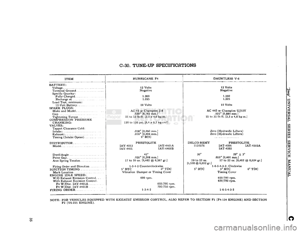
C-30.
TUNE-UP
SPECIFICATIONS
ITEM
BATTERY:
Voltage
Terminal
Ground Specific Gravity:
Fully
Charged Recharge at
Load
Test, minimum:
12-Volt Battery. .
SPARK PLUGS:
Make and Model
Gap
Tightening Torque
COMPRESSION
PRESSURE CRANKING:
VALVES:
Tappet Clearance Cold:
Intake
Exhaust:
Timing (Intake Opens)
DISTRIBUTOR
Model
Dwell
Angle
Point Gap
Arm
Spring Tension
Firing
Order and Direction ....
IGNITION TIMING.
Mark
Location
ENGINE
IDLE
SPEED: W/O
Exhaust Emission Control With Exhaust Emission Control
F4
W/Dist. IAY-4401A
F4
W/Dist. IAY-4401B
FIRING
ORDER HURRICANE
F4
DAUNTLESS
V-6
12 Volts
Negative
1.260 1.225
10 Volts
AC
45 or Champion J-8 .030"
[0,762
mm.]
25 to 33
lb-ft.
[3,5 a 4,6
kg-m.]
120 to 130 psi. [8,4 a 9,2
kg-cm2]
.018"
[0,460
mm.] .016"
[0,406
mm.]
9°
BTC
PRESTOLITE
IAY-4012
IAY-4401A
IAY-4401
IAY-4401B
42°
.020"
[0,508
mm.]
17 to 20 oz.
[0,482
@
0,567
gr.]
1-3-4-2
Counterclockwise
5° BTC
0° TDC
Vibration Damper or Timing Cover
600 rpm.
1-3-4-2
650/700
rpm.
700/750
rpm. 12 Volts
Negative
1.260 1.225
10 Volts
AC
44S or Champion UJ12Y .035"
[0,889
mm.]
25 to 35
lb-ft.
[3,5 a 4,8
kg-m.]
Zero (Hydraulic Lifters)
Zero (Hydraulic Lifters)
DELCO-REMY
1110376
PRESTOLITE
IAT-4501 IAT-4502A
IAT-4502
30°
19 to 23 oz.
[0,538
@
0,652
gr.'
5°
BTC
29°
± 3°
.016"
[0,401
mm.] 17 to 22 oz.
[0,482
1-6-5-4-3-2-
Clockwise
5°
BTC
Timing Cover
650/700
rpm.
650/700
rpm.
1-6-5-4-3-2
%
0,624
gr.]
0°
TDC
NOTE:
FOR
VEHICLES
EQUIPPED WITH EXHAUST
EMISSION
CONTROL, ALSO
REFER
TO
SECTION
Fl (F4-134
ENGINE)
AND
SECTION
F2
(V6-225
ENGINE).
Co O
Page 37 of 376
'Jeep9
UNIVERSAL SERIES SERVICE
MANUAL
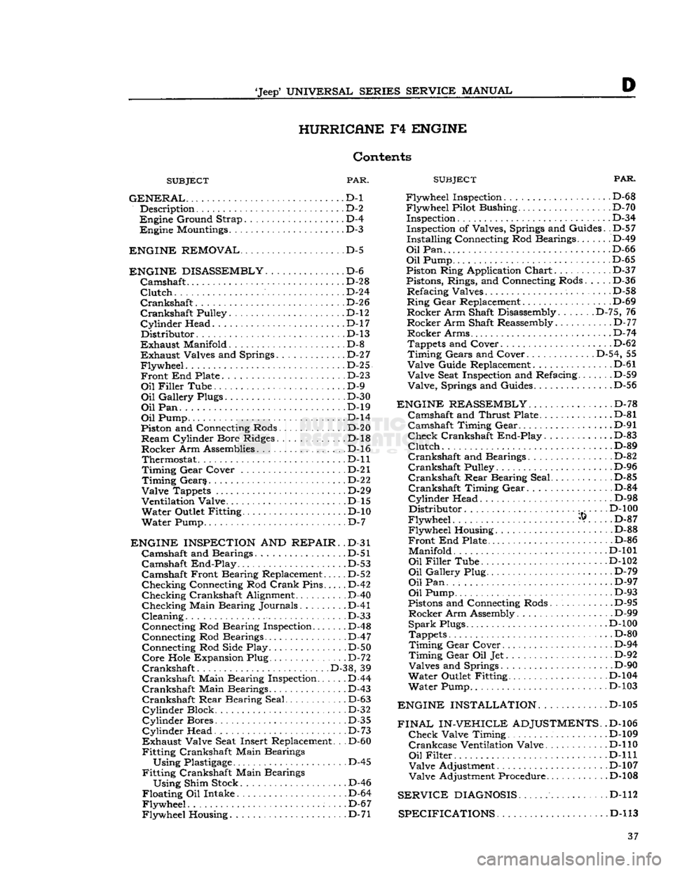
D HURRICANE
F4
ENGINE
Contents
SUBJECT
PAR.
GENERAL...
D-l Description D-2
Engine
Ground Strap D-4
Engine
Mountings D-3
ENGINE REMOVAL
D-5
ENGINE DISASSEMBLY
D-6
Camshaft
.......
D-28
Clutch
D-24
Crankshaft.
D-26
Crankshaft
Pulley. D-l2
Cylinder
Head. .D-17
Distributor.
.D-13
Exhaust
Manifold D-8
Exhaust
Valves and Springs D-2
7
Flywheel.
. D-25
Front
End Plate D-23
Oil
Filler
Tube D-9
Oil
Gallery Plugs D-30
Oil
Pan. . ...D-19
Oil
Pump D-l4
Piston and Connecting Rods. . . D-20
Ream
Cylinder Bore Ridges. D-l8
Rocker
Arm Assemblies D-l6 Thermostat D-ll
Timing
Gear
Cover . . D-21
Timing
Gears D-22
Valve
Tappets D-29
Ventilation Valve D-l5
Water
Outlet Fitting D-10
Water
Pump D-7
ENGINE INSPECTION
AND
REPAIR.
.D-31
Camshaft
and Bearings. D-51
Camshaft
End-Play
. . .D-53
Camshaft
Front Bearing Replacement..... D-52
Checking
Connecting Rod
Crank
Pins D-42
Checking
Crankshaft Alignment .
.
D-40
Checking
Main Bearing Journals. D-41
Cleaning.
. D-33 Connecting Rod Bearing Inspection D-48
Connecting Rod Bearings D-47 Connecting Rod Side Play D-50
Core
Hole Expansion Plug D-72
Crankshaft
.
.
D-38, 39
Crankshaft
Main Bearing Inspection D-44
Crankshaft
Main Bearings D-43
Crankshaft
Rear
Bearing Seal D-63
Cylinder
Block D-32
Cylinder
Bores D-35
Cylinder
Head. . . D-73
Exhaust
Valve Seat Insert Replacement. .
.
D-60
Fitting
Crankshaft Main Bearings
Using
Plastigage
D-45
Fitting
Crankshaft Main Bearings
Using
Shim Stock D-46
Floating
Oil Intake D-64
Flywheel.
. . .D-67
Flywheel
Housing D-71
SUBJECT
FAR.
Flywheel
Inspection. D-6 8
Flywheel
Pilot Bushing D-70 Inspection D-3 4
Inspection of Valves, Springs and Guides. .D-57
Installing
Connecting Rod Bearings....... D-49
Oil
Pan D-66
Oil
Pump D-65
Piston Ring Application
Chart
D-3 7
Pistons, Rings, and Connecting Rods..... D-36
Refacing
Valves
.
D-58
Ring
Gear
Replacement D-69
Rocker
Arm Shaft Disassembly. D-75, 76
Rocker
Arm Shaft Reassembly.
.
D-77
Rocker
Arms D-74
Tappets and Cover. . D-62
Timing
Gears and Cover D-54, 55
Valve
Guide Replacement D-61
Valve
Seat Inspection and Refacing D-59
Valve,
Springs and Guides D-56
ENGINE REASSEMBLY
D-78
Camshaft
and
Thrust
Plate .D-81
Camshaft
Timing
Gear
D-91
Check
Crankshaft
End-Play.
............D-83
Clutch.
...D-89
Crankshaft
and Bearings................ D-82
Crankshaft
Pulley D-96
Crankshaft
Rear
Bearing Seal.. .
.
D-85
Crankshaft
Timing
Gear
D-84
Cylinder
Head D-98
Distributor
D-l
00
Flywheel
®. . .. D-87
Flywheel
Housing D-88
Front
End Plate D-86
Manifold.......
D-101
Oil
Filler
Tube D-102
Oil
Gallery Plug. D-79
Oil
Pan. D-97
Oil
Pump D-93
Pistons and Connecting Rods D-95
Rocker
Arm Assembly D-99
Spark
Plugs. .D-100
Tappets D-80
Timing
Gear
Cover D-94
Timing
Gear
Oil Jet D-92
Valves
and Springs ... D-90
Water
Outlet Fitting D-104
Water
Pump D-103
ENGINE INSTALLATION.
............D-105
FINAL IN-VEHICLE
ADJUSTMENTS.
.D-106
Check
Valve Timing . . D-109
Crankcase
Ventilation Valve. D-l 10
Oil
Filter
, . .
...D-lll
Valve
Adjustment D-107
Valve
Adjustment Procedure D-l08
SERVICE
DIAGNOSIS
D-112
SPECIFICATIONS D-l
13 37
Page 38 of 376
HURRICANE
F4
ENGINE
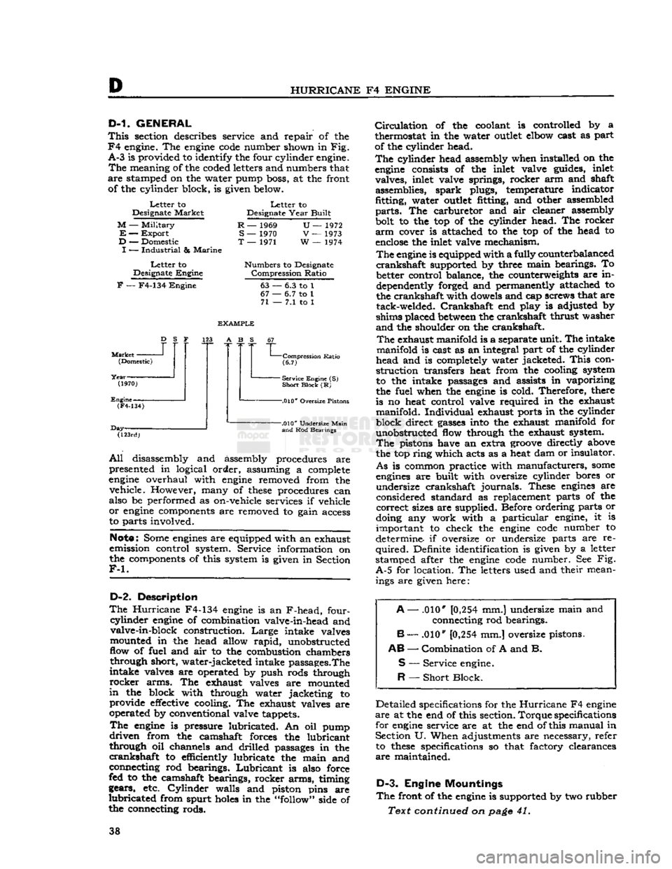
D-1.
GENERAL
This
section describes service and repair of the
F4
engine. The
engine
code
number shown in Fig.
A-3
is provided to identify the four cylinder engine.
The
meaning of the coded letters and numbers that
are
stamped on the water pump boss, at the front of the cylinder block, is given below.
Letter
to
Designate
Market
M
—
Military
E
—
Export
D
— Domestic
I
—
Industrial
&
Marine
Letter
to
Designate
Engine
Letter
to
Designate
Year
Built
R
— 1969
S
— 1970
T
— 1971
U—
1972
V
— 1973
W
— 1974
Numbers
to Designate
Compression
Ratio
F
— F4-134
Engine
63
67
•
71
-
6.3 to 1
•
6.7 to 1
-
7.1 to 1
Market
-
D
S F
(Domestic)
(1970)
Engine-
EXAMPLE
123 A B S
(F4-134)
Day- "L
Compression
Ratio
(6.7)
-
Service Engine (S)
Short
Block
(R)
-.010*
Oversize Pistons
(123rd)
-.010*
Undersize
Main
and
Rod Bearings
All
disassembly and assembly procedures are
presented in logical order, assuming a complete
engine
overhaul with
engine
removed from the vehicle. However, many of
these
procedures can
also be performed as on-vehicle services if vehicle
or
engine
components are removed to gain access
to parts involved.
Note:
Some
engines
are equipped with an exhaust
emission control system. Service information on
the components of this system is given in Section
F-l.
D-2.
Description
The
Hurricane
F4-134
engine
is an F-head, four-
cyiinder
engine
of combination valve-in-head and valve-in-block construction.
Large
intake valves
mounted in the head allow
rapid,
unobstructed
flow of fuel and air to the combustion chambers through short, water-jacketed intake passages.The
intake valves are operated by push rods through
rocker
arms. The exhaust valves are mounted
in
the block with through water jacketing to provide
effective
cooling. The exhaust valves are
operated by conventional valve tappets.
The
engine
is pressure lubricated. An oil pump
driven
from the camshaft forces the lubricant
through oil channels and drilled passages in the
crankshaft
to efficiently lubricate the main and
connecting rod bearings.
Lubricant
is also force
fed to the camshaft bearings, rocker arms, timing
gears, etc.
Cylinder
walls and piston pins are
lubricated
from spurt
holes
in the "follow" side of
the connecting rods.
Circulation
of the coolant is controlled by a
thermostat in the water
outlet
elbow cast as part
of the cylinder head.
The
cylinder head assembly when installed on the
engine
consists of the inlet valve guides, inlet valves, inlet valve springs, rocker arm and shaft assemblies, spark plugs, temperature indicator
fitting, water
outlet
fitting, and other assembled
parts.
The carburetor and air cleaner assembly
bolt to the top of the cylinder head. The rocker
arm
cover is attached to the top of the head to
enclose
the inlet valve mechanism.
The
engine
is equipped with a fully counterbalanced
crankshaft
supported by three main bearings. To better control balance, the counterweights are in
dependently forged and permanently attached to
the crankshaft with dowels and cap screws that are tack-welded.
Crankshaft
end play is adjusted by
shims placed
between
the crankshaft thrust washer
and
the shoulder on the crankshaft.
The
exhaust manifold is a separate unit. The intake
manifold is cast as an integral part of the cylinder
head and is completely water jacketed.
This
con
struction transfers heat from the cooling system
to the intake passages and assists in vaporizing
the fuel when the
engine
is cold. Therefore, there
is no heat control valve required in the exhaust manifold. Individual exhaust ports in the cylinder
block direct
gasses
into the exhaust manifold for unobstructed flow through the exhaust system.
The
pistons have an extra
groove
directly above
the top ring which acts as a heat dam or insulator.
As
is common practice with manufacturers,
some
engines
are built with oversize cylinder bores or undersize crankshaft journals. These
engines
are
considered standard as replacement parts of the
correct
sizes are supplied. Before ordering parts or
doing any work with a particular engine, it is important to check the
engine
code
number to
determine if oversize or undersize parts are re
quired.
Definite identification is given by a letter
stamped after the
engine
code
number. See Fig.
A-5
for location. The letters used and their mean ings are given here:
A
— .010*
[0,254
mm.] undersize main and
connecting rod bearings.
B
— .010"
[0,254
mm.] oversize pistons.
AB
—
Combination
of A and B.
S
—
Service
engine.
R
—
Short
Block.
Detailed specifications for the
Hurricane
F4
engine
are
at the end of this section.
Torque
specifications
for
engine
service are at the end of this manual in Section U. When adjustments are necessary, refer to
these
specifications so that factory clearances
are
maintained.
D-3.
Engine Mountings
The
front of the
engine
is supported by two rubber
Text continued on
page
41. 38
Page 39 of 376
'Jeep'
UNIVERSAL
SERIES
SERVICE
MANUAL
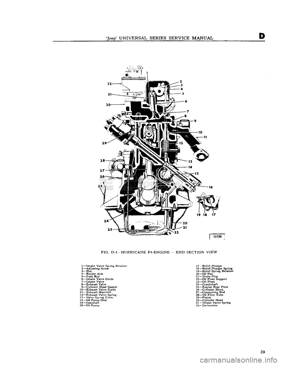
FIG.
D-l—HURRICANE
F4-ENGINE
— END
SECTION
VIEW
1— Intake Valve Spring Retainer
2—
Adjusting
Screw
3—
Nut
4— Rocker Arm
5—
Push
Rod
6— Intake Valve Guide 7— Intake Valve
8— Exhaust Valve
9—
Cylinder
Head
Gasket
10— Exhaust Valve Guide
11— Exhaust
Manifold
12—
Exhaust Valve Spring
13—
Valve
Spring Cover
14—
Oil
Pump
Gear
15— Camshaft
16—
Oil
Pump
17—
Relief
Plunger
18—
Relief
Plunger Spring
19—
Relief
Spring Retainer
20—
Oil
Pan
21—
Drain
Plug
22—
Oil
Float Support
23—
Oil
Float
24—
Crankshaft
25—
Engine
Rear
Plate
26—
Cylinder
Block
27—
Connecting Rod
28—
Oil
Filler
Tube
29—
Piston
30—
Cylinder
Head
31—
Intake Valve Spring
.12—Carburetor 39
Page 40 of 376
D
HURRICANE
F4
ENGINE ®
® ® ® ®
®
® @> ® ® ®® ® (§) 11759
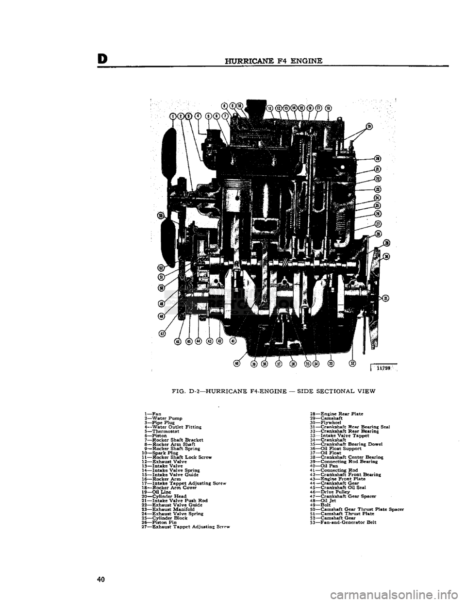
FIG.
D-2—HURRICANE F4-ENGINE
—
SIDE SECTIONAL VIEW
1— Fan
2— Water Pump
3— Pipe Plug
4— Water Outlet Fitting 5— Thermostat
6— Piston
7— Rocker Shaft Bracket
8— Rocker Arm Shaft
9— Rocker Shaft Spring
10—
Spark
Plug
11— Rocker Shaft Lock Screw
12—
Exhaust
Valve 13— Intake Valve
14— Intake Valve Spring
15— Intake Valve Guide
16— Rocker Arm
17— Intake Tappet Adjusting Screw
18— Rocker Arm Cover 19—
Oil
Line
20—
Cylinder
Head
21— Intake Valve Push Rod
22—
Exhaust
Valve Guide
23—
Exhaust
Manifold
24—
Exhaust
Valve Spring
25—
Cylinder
Block
26— Piston Pin 27—
Exhaust
Tappet Adjusting Screw 28—
Engine
Rear
Plate
29— Camshaft
30— Flywheel 31—
Crankshaft
Rear Bearing Seal
32—
Crankshaft
Rear Bearing
33— Intake Valve Tappet
34—
Crankshaft
35—
Crankshaft
Bearing Dowel
36—
Oil
Float Support
37—
Oil
Float
38—
Crankshaft
Center Bearing
39— Connecting Rod Bearing
40—
Oil
Pan
41— Connecting Rod
42—
Crankshaft
Front Bearing
43— Engine Front Plate
44—
Crankshaft
Gear
45—
Crankshaft
Oil Seal
46— Drive Pulley
47—
Crankshaft
Gear Spacer 48—
Oil
Jet
49— Bolt 50— Camshaft Gear Thrust Plate Spacer
51—
Camshaft Thrust Plate
52— Camshaft Gear
53— Fan-and-Generator Belt 40
Page 41 of 376
'Jeep*
UNIVERSAL SERIES
SERVICE
MANUAL
D
insulator
mountings attached to the frame side
rail
brackets. The
rear
of the engine-transmission
assembly is supported by a rubber insulator
mounting under the
rear
of the transmission on
the frame center cross member.
This
cross member
is bolted to the frame side
rails
so that it can be
dropped when removing the transmission or engine-
transmission
assembly. The rubber insulators allow
free side and vertical oscillation to effectively
neutralize
engine
vibration at the source.
The
rubber
insulator mountings should be inspected
for separation and deterioration by jacking the
power plant away from the frame, near the sup
ports. Vibration cannot be effectively absorbed by
separated or worn insulators. They should be re placed if faulty.
D-4.
Engine
Ground
Strap
To
be sure of an
effective
ground for the electrical
circuits,
a ground strap bridges the right front
engine
support to the chassis. The connections of this strap must be kept clean and tight for proper
operation of the electrical system.
D-5. ENGINE REMOVAL
Should
the
engine
require overhauling, it is neces
sary
to remove it from the vehicle. The following procedure covers removal of the
engine
only.
The
engine, transmission and transfer case may be
removed as a unit by removing (in addition to the following procedure) the radiator guard and the
access plates in the floor pan.
a.
Drain
the cooling system by opening the
drain
cocks at the
bottom
of the radiator and lower right
side of the cylinder block.
b.
Disconnect the battery at the positive terminal
to avoid the possibility of short
circuit.
c. Remove the air cleaner horn from the carburetor
and
disconnect the breather
hose
at the oil filler
pipe.
d.
Disconnect the carburetor choke and throttle controls by loosening the clamp
bolts
and set
screws.
e. Disconnect the fuel-tank-to-fuel-pump line at the fuel pump by unscrewing the connecting nut.
f- Plug the fuel line to prevent fuel leakage.
g. Remove the radiator and radiator grille support
rods.
h. Remove the upper and lower radiator
hoses
by
loosening the
hose
clamps and slipping the clamps
back
on the
hose.
If so equipped, remove the heater
hoses
(one to the water pump, one to the
rear
of
the cylinder head) in the same manner.
i.
Remove the four
bolts
from the fan hub and re
move
the fan hub and fan blades.
j.
Remove the four radiator attaching screws. Re
move
the radiator and shroud as one unit, k. Remove the starting motor cables. Remove the
starting
motor.
I.
Disconnect the wires from the alternator or
generator. Disconnect the ignition
primary
wire
at the ignition coil.
NOTE:
ON
ENGINES EQUIPPED WITH EX
HAUST
EMISSION CONTROL, REMOVE THE
AIR
PUMP,
AIR
DISTRIBUTION
MANI
FOLD,
AND
ANTI-BACKFIRE (DIVERTER)
VALVE.
SEE SECTION
Fl
FOR PROCEDURE.
m.
Disconnect the oil pressure and temperature
sending unit wires at the units.
n.
Disconnect the exhaust pipe at the exhaust
manifold by removing the stud nuts.
o.
Disconnect the
spark
plug cables at the plugs
and
remove the cable bracket from the rocker arm cover stud.
p.
Remove the rocker arm cover by removing the
attaching stud nuts.
q.
Attach a lifting bracket to the
engine
using
existing head bolt locations. Be sure the
bolts
selected
will
hold the
engine
with the weight
balanced.
Attach lifting bracket to a boom hoist,
or
other lifting device, and take up all slack,
r.
Remove the two nuts and
bolts
from each front
engine
support. Disconnect the
engine
ground strap.
Remove the
engine
supports.
Lower
the
engine
slightly to permit access to the two top
bolts
on
the flywheel housing.
s. Remove the
bolts
which attach the flywheel
housing to the engine.
t.
Pull
the
engine
forward, or
roll
the vehicle back
wards,
until the clutch clears the flywheel housing.
Lift
the
engine
from the vehicle.
D-6. ENGINE DISASSEMBLY
Engine
disassembly is presented in the sequence to be followed when the
engine
is to be completely
overhauled after removal from the vehicle. Some
of the operations of the procedure are also ap
plicable
separately with the
engine
in the vehicle,
provided
that wherever necessary the part of the
engine
to be worked on is first made accessible by
removal
of
engine
accessories or other parts.
When
the disassembly operations are performed
with
the
engine
out of the vehicle, it is assumed,
in
this procedure, that all of the accessories have been removed
prior
to starting the disassembly
and
the oil has been drained.
In
addition to the instructions covering operations
for disassembling the
engine
out of the vehicle,
special
instructions are given to cover different
operations required when disassembly is
done
with the
engine
installed.
During
disassembly operations, the
engine
should
be mounted in a suitable
engine
repair
stand. Where
practicable,
modify or adapt an existing repair
stand
as necessary to accommodate the engine. If
an
engine
repair stand is not used, take care to
perform
disassembly operations in a manner that
will
protect personnel against an accident and the
engine
and its parts against damage.
NOTE:
If the
engine
is being disassembled because
of possible valve failure, check the valve tappet
clearance
before disassembly. Improper valve
clearance
could be the possible cause of valve
failure,
indicating a need for more frequent valve
checks and adjustments. 41