check engine JEEP CJ 1953 Workshop Manual
[x] Cancel search | Manufacturer: JEEP, Model Year: 1953, Model line: CJ, Model: JEEP CJ 1953Pages: 376, PDF Size: 19.96 MB
Page 60 of 376
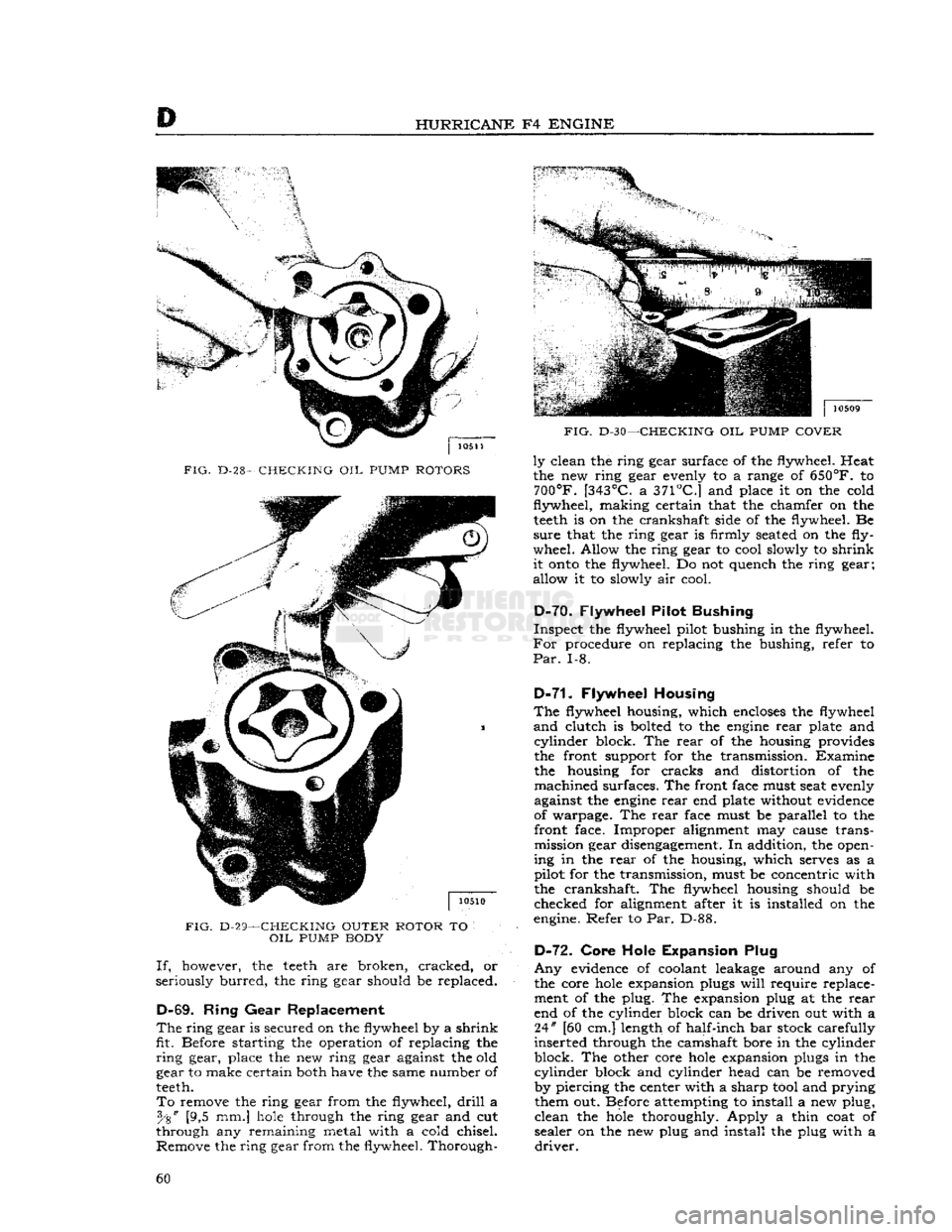
HURRICANE
F4
ENGINE
FIG.
D-28-
CHECKING
OIL
PUMP
ROTORS
FIG.
D-29—CHECKING OUTER ROTOR
TO
OIL
PUMP
BODY If,
however, the
teeth
are broken, cracked, or
seriously
burred,
the ring gear should be replaced.
D-69.
Ring
Gear
Replacement
The
ring
gear
is secured on the flywheel by a
shrink
fit. Before starting the operation of replacing the
ring
gear, place the new ring gear against the old
gear to make certain both have the same number of
teeth.
To
remove the ring gear from the flywheel,
drill
a [9,5 mm.]
hole
through the ring gear and cut
through any remaining metal with a cold chisel. Remove the ring gear from the flywheel. Thorough-
FIG.
D-30—CHECKING
OIL
PUMP
COVER
ly
clean the ring gear surface of the flywheel. Heat
the new ring gear evenly to a range of
650°F.
to
700°F.
[343°C.
a
371°C.]
and place it on the cold
flywheel,
making
certain that the chamfer on the
teeth
is on the crankshaft side of the flywheel. Be
sure
that the ring gear is firmly seated on the fly
wheel. Allow the ring gear to cool slowly to
shrink
it
onto
the flywheel. Do not quench the ring gear;
allow it to slowly air cool.
D-7Q.
Flywheel Pilot Bushing
Inspect
the flywheel pilot bushing in the flywheel.
For
procedure on replacing the bushing, refer to
Par.
1-8.
D-71.
Flywheel Housing
The
flywheel housing, which
encloses
the flywheel
and
clutch is bolted to the
engine
rear
plate and
cylinder
block. The
rear
of the housing provides
the front support for the transmission. Examine the housing for cracks and distortion of the
machined
surfaces. The front face must seat evenly
against the
engine
rear
end plate without evidence
of warpage. The
rear
face must be parallel to the front face. Improper alignment may cause transmission gear disengagement. In addition, the open
ing in the
rear
of the housing, which serves as a
pilot for the transmission, must be concentric with the crankshaft. The flywheel housing should be
checked for alignment after it is installed on the
engine. Refer to Par. D-88.
D-72.
Core Hole Expansion Plug
Any
evidence of coolant leakage around any of
the core
hole
expansion plugs
will
require replace ment of the plug. The expansion plug at the
rear
end of the cylinder block can be driven out with a 24" [60 cm.] length of half-inch bar stock carefully
inserted through the camshaft bore in the cylinder
block. The other core
hole
expansion plugs in the
cylinder
block and cylinder head can be removed
by piercing the center with a sharp tool and prying them out. Before attempting to install a new plug,
clean
the
hole
thoroughly. Apply a thin coat of
sealer on the new plug and install the plug with a
driver.
60
Page 62 of 376
D
HURRICANE
F4
ENGINE d.
Remove the intake valve adjusting screw lock-
nuts from each of the rocker arm valve lash ad
justing
screws. Remove the screws from the rocker
arms.
D-76.
Inspection and
Repair
Run
a round wire brush through the bore of the
rocker
arm shaft and clean out the drilled oil holes.
Clean
out the oil
holes
in the rocker arm shaft
brackets,
and the oil
holes
and
grooves
in the bores
of the rocker arm.
Inspect
the diameter of the shaft at the rocker arm
bearing
areas. Replace the shaft if there are scores
or
abrasion marks along the length of the shaft.
Check
the shaft for alignment by rolling it across
a
smooth level surface. If the shaft
will
not
roll
freely, or if it rolls with a bumping motion, the
shaft is out of alignment and must be replaced.
Inspect
the threads of the adjusting screw
hole
in
the rocker arms and if necessary clean with a
proper
size tap. Replace the adjusting screw lock-
nut or the adjusting screw if either part is damaged
or
deformed.
Inspect
the threads in the tapped
hole
in the top
of the rocker arm shaft brackets and if necessary
clean
with a proper size tap. Replace the bracket
if
either side is worn or scored.
D-77.
Reassembly
a.
Install
two rocker arm shaft plugs, one in each
end of the shaft. Slide two
rocker
arm
shaft brackets
onto
the center of the shaft. Align the tapped
holes
in
the brackets with the drilled
holes
in the top of
the shaft and install the rocker arm shaft lock
screws,
making sure the points of the screws enter
the drilled
holes
in the shaft.
b.
Screw the intake valve adjusting screws into
the rocker arms and install the locknuts.
c.
The rocker arms are paired; that is, two of the
arms
are angled to the right and two are angled to
the left. One of each type is used on each end of
the rocker arm shaft. Slide a rocker arm with the
adjusting
screw end of the rocker arm angling
away
from the bracket
onto
the shaft so that the
adjusting
screw is on the same side of the shaft
as the mounting
hole
in the bracket.
d.
Temporarily
secure the end bracket in place by
installing
a rocker arm cover stud in the tapped
opening in the top of the support.
e. Assemble the parts on the
opposite
end of the
rocker
arm shaft repeating
steps
c and d above.
D-78. ENGINE REASSEMBLY
The
engine
reassembly procedure in the following
paragraphs
is given in the sequence to be followed
when the
engine
is being completely overhauled.
Individual
inspection,
repair,
and fitting operations
previously covered in detail are made throughout
the reassembly procedure. The reassembly pro
cedure
does
not cover accessories. If a new cylinder
block
fitted with pistons is used, many of the
operations
will
not be required.
Mount
the cylinder block in an
engine
repair stand.
If
an
engine
stand is not available, perform the fol
lowing reassembly operation in a manner designed to protect personnel against an accident and the
engine
and its parts against damage.
Note:
During
engine
reassembly, use Perfect Seal
Aerosol
Spray
Sealer
Part
No.
994757
on all
engine
gaskets to ensure against vacuum, oil, gasoline and
water
leaks. Apply to head gaskets, valve covers,
water
pumps, oil pan gaskets, radiator and heater
hose
connections, felt gaskets, gasoline and oil line
connections, stud bolts,
spark
plug threads, and
grease retainer washers. Refer to manufacturer's in
structions on container for proper application pro
cedure.
D-79.
Install
Oil
Gallery
Plug
Coat
plug threads with a suitable sealing compound
and
install the plugs in the front and
rear
ends of
the oil gallery in the cylinder block and the
rear
end of the cylinder head. Torque the plugs 20 to 25 lb-ft. [2,8 a 3,4 kg-m.].
There
is also a pipe plug
(}/g,f
[3,2 mm.] slotted, headless) in the opening in the main oil gallery inside the cylinder block at No. 2 cylinder and another pipe plug
(}/g
"
square-head) in the opening
in
the oil passage directly below the oil pump intake
passage. If
these
two pipe plugs were removed,
make
certain they are reinstalled in the locations
described above or the counterweight of the
crankshaft
might strike the projecting head of the
square-head
plug.
D-80.
Install
Tappets
Turn
the block upside down. Beginning at the
rear
end of the cylinder block, install the intake
and
exhaust valve tappets in the tappet bores in the cylinder block in the following order: one
exhaust, two intake, two exhaust, two intake, and
finally
one exhaust valve tappet.
Check
the tappet to bore fit of each tappet as it
is installed in the block. If the stem-to-block
clearance
tolerance of .0005" to .002" [0,0127 a
0,051 mm.] is
exceeded
install a new tappet fitting
within
this tolerance or ream the bore to accomo date the next oversize tappet which is available
in
.004" oversize.
D-81.
Install
Camshaft and
Thrust
Plate
Lubricate
all camshaft bearings and cam surfaces generously with clean, light
engine
oil.
Carefully,
so not to damage or score the camshaft front bear
ing,
install the camshaft, locating it properly in the bearings. Do not allow the
rear
end of the camshaft to strike sharply against the expansion plug
installed
in the
rear
end of the bore.
Install
the camshaft thrust plate. Slide the thrust
plate spacer
onto
the end of the camshaft with the
beveled inner
edge
of the spacer facing the cam
shaft. If the same camshaft is being reinstalled,
install
any shims previously removed. These shims
are
placed
between
the camshaft shoulder and the
spacer.
Torque the thrust plate attaching
bolts
20
to 26 lb-ft. [2,8 a 3,6 kg-m.].
End
play of the camshaft is determined by running
clearance
between
the
rear
face of the camshaft
gear and the thrust plate. The standard clearance 62
Page 63 of 376
![JEEP CJ 1953 Workshop Manual
Jeep
UNIVERSAL SERIES SERVICE
MANUAL
D
is .004" to .007"
[0,102
a 0,178 mm.] as measured
by a dial indicator. Should a check
show
too little
end play, place a shim of suitable thickness
JEEP CJ 1953 Workshop Manual
Jeep
UNIVERSAL SERIES SERVICE
MANUAL
D
is .004" to .007"
[0,102
a 0,178 mm.] as measured
by a dial indicator. Should a check
show
too little
end play, place a shim of suitable thickness](/img/16/57040/w960_57040-62.png)
'Jeep'
UNIVERSAL SERIES SERVICE
MANUAL
D
is .004" to .007"
[0,102
a 0,178 mm.] as measured
by a dial indicator. Should a check
show
too little
end play, place a shim of suitable thickness
between
the camshaft shoulder and the spacer. Too much
end play may be corrected by removing shims or
dressing off the spacer a slight amount. See Fig. D-33.
D-82. Install Crankshaft and Bearings
Fit
the three upper main bearings
into
their
respective
locations
in the cylinder block. Fit the
three lower main bearings
into
their respective
bearing caps.
NOTE:
It is
possible
to incorrectly install the front main bearing. The bearing is properly installed in
the cap with the narrower of the two radial oil
grooves
toward the front
edge
of the cap. If this
bearing is not properly installed, the oil
grooves
in
the two halves of the bearing will not match at the
parting line and premature failure of the bearing
will
result.
Lubricate
all bearing surfaces
generously
with
clean, light
engine
oil. Place the crankshaft in
position
in the cylinder block and install the main
bearing caps. Torque the
bolts
65 to 75 lb-ft.
[9,0 a 10,4 kg-m.] rotating the crankshaft after
each bearing cap is
tightened
D-83. Check Crankshaft End-Play
End
play of the crankshaft is set by the running
clearance
between
the crankshaft thrust washer
and the front
face
of the front main bearing. The
standard end play is .004" to .006"
[0,102
a 0,152
mm.] which is controlled by .002"
[0,051
mm.]
shims placed
between
the thrust washer and the
shoulder on the crankshaft. Check the end play
with a dial indicator as shown in
Fig.
D-34. If clear ance is incorrect, adjustment is made by adding or
removing shims.
Install
the thrust washer with the
beveled
inner
edge
toward the front bearing.
10668
FIG.
D-33—VALVES, CAMSHAFT,
AND
TIMING GEARS
1— Nut
2—
Left
Rocker Arm
3—
Rocker
Arm Shaft Spring
4—
Rocker
Shaft
Lock
Screw 5—
Rocker
Shaft
6— Nut 7—
Right
Rocker Arm
8—
Rocker
Arm Shaft Bracket
9—
Intake
Valve Tappet Adjusting Screw
10—
Intake
Valve Upper Retainer
Lock
11—
Oil
Seal
12—
Intake
Valve Spring Upper Retainer 13—
Intake
Valve Spring
14—
Intake
Valve Push Rod 15—
Intake
Valve
16—
Intake
Valve Tappet
17—
Camshaft
18—
Camshaft
Front Bearing
19—
Camshaft
Thrust Plate Spacer
20—
Camshaft
Thrust Plate
21— Bolt and Lockwasher
22— Bolt 13—Lockwasher
24—Camshaft
Gear
Washer 25—
Crankshaft
Gear
26—
Camshaft
Gear
27— Woodruff Key No. 9
28—
Exhaust
Valve Tappet
29— Tappet Adjusting Screw
30—
Spring
Retainer
Lock
31— Roto Cap Assembly
32—
Exhaust
Valve Spring
33—
Exhaust
Valve
34—
Rocker
Shaft Support Stud
35—
Washer
36—
Rocker
Arm Cover Stud 63
Page 65 of 376
'Jeep'
UNIVERSAL
SERIES
SERVICE
MANUAL
D
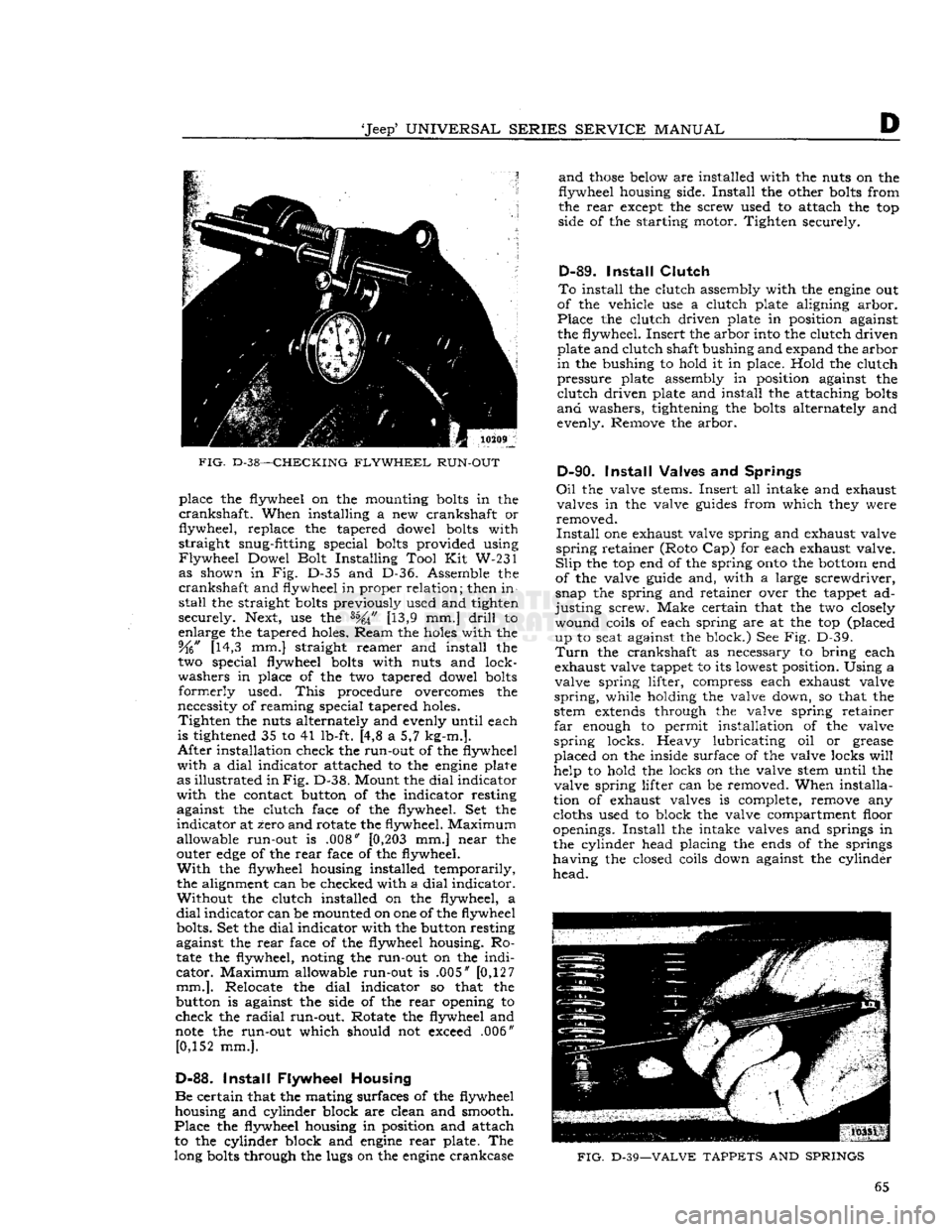
FIG.
D-38—CHECKING
FLYWHEEL
RUN-OUT
place the flywheel on the mounting
bolts
in the
crankshaft.
When installing a new crankshaft or
flywheel, replace the tapered dowel
bolts
with
straight snug-fitting special
bolts
provided using
Flywheel
Dowel Bolt Installing Tool Kit W-231 as shown in Fig. D-35 and D-36. Assemble the
crankshaft
and flywheel in proper relation; then in
stall
the straight
bolts
previously used and tighten
securely. Next, use the [13,9 mm.]
drill
to
enlarge the tapered holes. Ream the
holes
with the 5fo" [14,3 mm.] straight reamer and install the
two special flywheel
bolts
with nuts and lock
washers in place of the two tapered dowel
bolts
formerly
used.
This
procedure overcomes the
necessity of reaming special tapered holes.
Tighten
the nuts alternately and evenly until each
is tightened 35 to 41 lb-ft. [4,8 a 5,7 kg-m.].
After
installation check the run-out of the flywheel
with
a
dial
indicator attached to the
engine
plate
as illustrated in
Fig.
D-38. Mount the
dial
indicator
with
the contact button of the indicator resting against the clutch face of the flywheel. Set the
indicator
at zero and rotate the flywheel. Maximum
allowable run-out is .008"
[0,203
mm.] near the
outer
edge
of the
rear
face of the flywheel.
With
the flywheel housing installed temporarily,
the alignment can be checked with a
dial
indicator. Without the clutch installed on the flywheel, a
dial
indicator can be mounted on one of the flywheel bolts. Set the
dial
indicator with the button resting
against the
rear
face of the flywheel housing. Ro
tate
the flywheel, noting the run-out on the
indi
cator.
Maximum allowable run-out is .005" [0,127
mm.].
Relocate the
dial
indicator so that the
button is against the side of the
rear
opening to
check the
radial
run-out. Rotate the flywheel and
note
the run-out which should not exceed .006" [0,152 mm.].
D-88.
Install
Flywheel Housing
Be
certain that the mating surfaces of the flywheel housing and cylinder block are clean and smooth.
Place
the flywheel housing in position and attach to the cylinder block and
engine
rear
plate. The
long
bolts
through the lugs on the
engine
crankcase
and
those
below are installed with the nuts on the
flywheel housing side.
Install
the other
bolts
from
the
rear
except the screw used to attach the top
side of the starting motor. Tighten securely.
D-89.
Install
Clutch
To
install the clutch assembly with the
engine
out
of the vehicle use a clutch plate aligning arbor.
Place
the clutch driven plate in position against
the flywheel. Insert the arbor into the clutch driven plate and clutch shaft bushing and expand the arbor
in
the bushing to hold it in place. Hold the clutch
pressure plate assembly in position against the
clutch
driven plate and install the attaching
bolts
and
washers, tightening the
bolts
alternately and
evenly. Remove the arbor.
D-90.
Install
Valves and Springs
Oil
the valve stems. Insert all intake and exhaust valves in the valve
guides
from which they were
removed.
Install
one exhaust valve spring and exhaust valve
spring
retainer (Roto Cap) for each exhaust valve.
Slip
the top end of the spring
onto
the
bottom
end
of the valve guide and, with a large screwdriver,
snap the spring and retainer over the tappet ad
justing
screw. Make certain that the two closely wound coils of each spring are at the top (placed up to seat against the block.) See Fig. D-39.
Turn
the crankshaft as necessary to bring each
exhaust valve tappet to its lowest position. Using a
valve spring lifter, compress each exhaust valve
spring,
while holding the valve down, so that the
stem
extends
through the valve spring retainer
far
enough to permit installation of the valve
spring
locks. Heavy lubricating oil or grease
placed on the inside surface of the valve locks
will
help to hold the locks on the valve stem until the valve spring lifter can be removed. When installa
tion of exhaust valves is complete, remove any
cloths used to block the valve compartment floor
openings.
Install
the intake valves and springs in the cylinder head placing the ends of the springs
having the closed coils down against the cylinder
head.
FIG.
D-39—VALVE
TAPPETS
AND
SPRINGS
65
Page 66 of 376
D
HURRICANE
F4
ENGINE
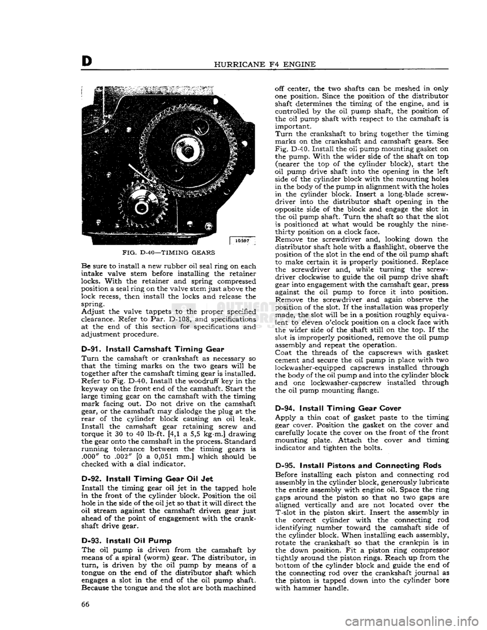
FIG.
D-40—TIMING
GEARS Be
sure
to install a new rubber oil
seal
ring on each
intake
valve stem before installing the retainer
locks.
With
the retainer and spring compressed position a
seal
ring
on the valve stem just above the
lock
recess, then install the locks and release the
spring.
Adjust
the valve tappets to the proper specified
clearance.
Refer to Par. D-108, and specifications
at the end of this section for specifications and
adjustment procedure.
D-91.
Install
Camshaft
Timing
Gear
Turn
the camshaft or crankshaft as necessary so
that the timing marks on the two gears
will
be
together
after the camshaft timing gear is installed.
Refer
to Fig. D-40.
Install
the woodruff key in the key way on the front end of the camshaft.
Start
the large timing gear on the camshaft with the timing
mark
facing out. Do not drive on the camshaft gear, or the camshaft may
dislodge
the plug at the
rear
of the cylinder block causing an oil leak.
Install
the camshaft gear retaining screw and
torque it 30 to 40 lb-ft. [4,1 a 5,5 kg-m.] drawing
the gear
onto
the camshaft in the process. Standard
running
tolerance
between
the timing gears is .000" to .002" [0 a 0,051 mm.] which should be
checked with a
dial
indicator.
D-92.
Install
Timing
Gear
Oil Jet
Install
the timing gear oil jet in the tapped
hole
in
the front of the cylinder block. Position the oil
hole
in the side of the oil jet so that it
will
direct the
oil
stream against the camshaft driven gear just
ahead
of the point of
engagement
with the
crank
shaft drive gear.
D-93.
Install
Oil Pump
The
oil pump is driven from the camshaft by means of a
spiral
(worm) gear. The distributor, in
turn,
is driven by the oil pump by means of a
tongue
on the end of the distributor shaft which
engages
a slot in the end of the oil pump shaft.
Because the
tongue
and the slot are both machined off center, the two shafts can be meshed in only
one position. Since the position of the distributor shaft determines the timing of the engine, and is
controlled by the oil pump shaft, the position of the oil pump shaft with respect to the camshaft is
important.
Turn
the crankshaft to bring
together
the timing
marks
on the crankshaft and camshaft gears. See
Fig.
D-4 0.
Install
the oil pump mounting gasket on
the pump.
With
the wider side of the shaft on top
(nearer
the top of the cylinder block), start the
oil
pump drive shaft into the opening in the left side of the cylinder block with the mounting
holes
in
the body of the pump in alignment with the
holes
in
the cylinder block. Insert a long-blade screw
driver
into the distributor shaft opening in the
opposite
side of the block and
engage
the slot in the oil pump shaft.
Turn
the shaft so that the slot is positioned at what would be roughly the nine-
thirty
position on a clock face. Remove tne screwdriver and, looking down the
distributor
shaft
hole
with a flashlight, observe the position of the slot in the end of the oil pump shaft
to make certain it is properly positioned. Replace the screwdriver and, while turning the screw
driver
clockwise to guide the oil pump drive shaft
gear into
engagement
with the camshaft gear, press
against the oil pump to force it into position. Remove the screwdriver and again observe the
position of the slot. If the installation was properly made, the slot
will
be in a position roughly equiva
lent to eleven o'clock position on a clock face with
the wider side of the shaft
still
on the top. If the
slot is improperly positioned, remove the oil pump
assembly and repeat the operation.
Coat
the threads of the capscrews with gasket
cement and secure the oil pump in place with two
lockwasher-equipped capscrews installed through the body of the oil pump and into the cylinder block
and
one lockwasher-capscrew installed through
the oil pump mounting flange.
D-94.
Install
Timing
Gear
Cover
Apply
a thin coat of gasket paste to the timing
gear cover. Position the gasket on the cover and
carefully
locate the cover on the front of the front mounting plate. Attach the cover and timing
indicator
and tighten the bolts.
D-95.
Install
Pistons and Connecting Rods
Before installing each piston and connecting rod assembly in the cylinder block, generously lubricate
the entire assembly with
engine
oil. Space the ring
gaps
around the piston so that no two
gaps
are
aligned vertically and are not located over the
T-slot
in the piston
skirt.
Insert the assembly in
the correct cylinder with the connecting rod
identifying number toward the camshaft side of
the cylinder block. When installing each assembly, rotate the crankshaft so that the
crankpin
is in
the down position. Fit a piston ring compressor
tightly around the piston rings. Reach up from the
bottom
of the cylinder block and guide the end of
the connecting rod over the crankshaft
journal
as
the piston is tapped down into the cylinder bore
with
hammer handle. 66
Page 68 of 376
D
HURRICANE
F4
ENGINE
D-101.
Install
Manifold
If
manifold studs were removed for replacement,
apply sealer on the stud threads
before
installing
a
new stud.
See Section Fl for exhaust emission controlled
engines.
Make
certain that no foreign objects are inside the manifold and that all
passages
are clear. Place a
new set of manifold
gaskets
in position on the side
of the cylinder block.
Then,
carefully slide the manifold
onto
the studs and against the cylinder block being careful not to damage the gaskets.
Torque
all manifold attaching nuts evenly 29 to
35 lb-ft. [4,0 a 4,8 kg-m.].
D-102.
Install
Oil
Filler
Tube
When
installing the oil filler tube, be sure that the
beveled lower end is away from the crankshaft.
Place a
piece
of
hard
wood
over the top of the
tube
to prevent damage to the cap gasket seat.
D-103.
Install
Water Pump
Make
certain that the mating surfaces of the water pump and the cylinder block are clean and smooth.
Install
the gasket on the
flange
of the pump and
install
the pump in position on the cylinder block.
Torque
the water pump attaching
bolts
alternately
and
evenly 12 to 17 lb-ft. [1,7 a 2,3 kg-m.].
D-104.
Install
Water Outlet Fitting
Install
the thermostat and the water
outlet
fitting.
Torque
the water
outlet
fitting attaching
bolts
20
to 25 lb-ft. [2,8 a 3,4 kg-m.].
FIG.
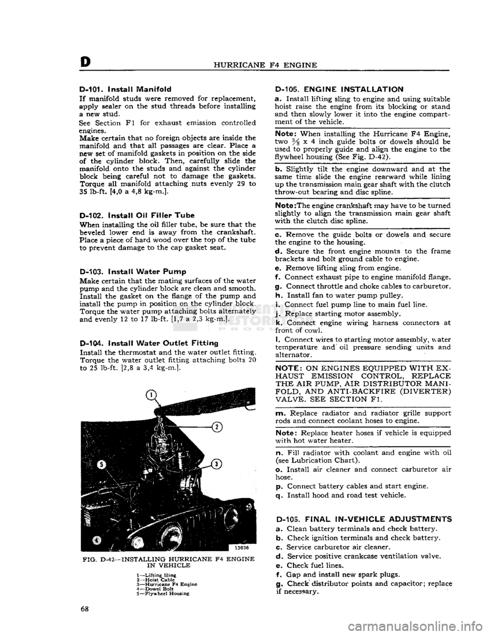
D-42—INSTALLING HURRICANE F4 ENGINE
IN
VEHICLE
1—
Lifting
Sling
2— Hoist
Cable
3—
Hurricane
F4 Engine
4— Dowel Bolt
5—
Flywheel
Housing
D-105.
ENGINE INSTALLATION
a.
Install
lifting sling to
engine
and using suitable hoist raise the
engine
from its blocking or stand
and
then slowly lower it
into
the
engine
compartment of the vehicle.
Note:
When installing the
Hurricane
F4 Engine,
two % x 4 inch
guide
bolts
or
dowels
should be
used to properly
guide
and align the
engine
to the
flywheel housing (See Fig. D-42).
b. Slightly tilt the
engine
downward and at the
same time slide the
engine
rearward
while lining up the transmission main gear shaft with the clutch
throw-out bearing and disc spline.
Note
:The
engine
crankshaft may have to be turned
slightly to align the transmission main gear shaft
with the clutch disc spline.
c. Remove the
guide
bolts
or
dowels
and secure
the
engine
to the housing.
d.
Secure the front
engine
mounts to the frame brackets and
bolt
ground cable to
engine.
e. Remove lifting sling from
engine.
f. Connect exhaust pipe to
engine
manifold flange.
g. Connect throttle and choke cables to carburetor.
h.
Install
fan to water pump pulley.
i.
Connect fuel pump line to main fuel line,
j.
Replace starting motor assembly. k. Connect
engine
wiring harness connectors at
front of cowl.
I.
Connect wires to starting motor assembly, water
temperature and oil pressure sending units and alternator.
NOTE:
ON
ENGINES EQUIPPED WITH EX
HAUST
EMISSION CONTROL,
REPLACE
THE
AIR
PUMP,
AIR
DISTRIBUTOR
MANI
FOLD,
AND
ANTI-BACKFIRE (DIVERTER)
VALVE.
SEE
SECTION
Fl.
m. Replace radiator and radiator grille support
rods and connect coolant
hoses
to
engine.
Note:
Replace heater
hoses
if vehicle is equipped
with hot water heater.
n. Fill
radiator with coolant and
engine
with oil
(see
Lubrication
Chart).
o.
Install
air cleaner and connect carburetor air
hose.
p. Connect battery cables and start
engine,
q.
Install
hood
and road
test
vehicle.
D-103.
FINAL
IN-VEHICLE
ADJUSTMENTS
a.
Clean
battery terminals and check battery. b.
Check
ignition terminals and check battery.
c. Service carburetor air cleaner.
d.
Service positive crankcase ventilation valve.
e.
Check
fuel lines. f. Gap and install new
spark
plugs.
g.
Check
distributor
points
and capacitor; replace
if
necessary. 68
Page 69 of 376
'Jeep9
UNIVERSAL
SERIES
SERVICE
MANUAL
h.
Check
ignition (distributor) timing; reset if
necessary.
i.
Check
carburetor
adjustments; reset if necessary,
j.
With
engine
fully warmed up, tighten cylinder
head and manifold
bolts
and nuts to specified
torque.
Check
cylinder head gaskets and
bolts
for
air
or coolant leaks.
Note:
Tightness of cylinder head
bolts
should be
checked and corrected after 500 to 600 miles [800
a
960 km.] of normal operation.
k.
Check
fan belt tension; adjust if necessary.
I.
Check
for and correct any oil leak, fuel leak or
coolant leak.
D-107.
VALVE
ADJUSTMENT
Proper
valve adjustment is important to prevent
burning
of valves and poor
engine
performance.
This
adjustment consists of obtaining a specified
lash
in the valve mechanism. The exhaust valve
tappets and the intake valve rocker arms should be adjusted to the proper clearance with the
engine
cold (at room temperature). Valve clearance can
be properly adjusted only when the tappet is on the
heel or low portion of the cam.
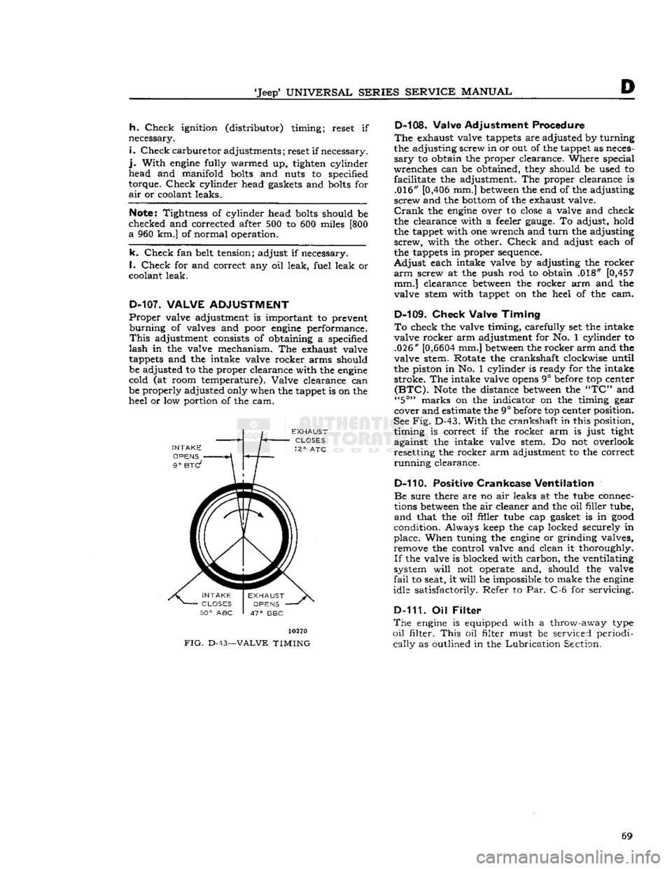
INTAKE
OPENS
9°
BTC?
FIG.
D-43-
10270
-VALVE
TIMING
D-108. Valve Adjustment Procedure
The
exhaust valve tappets are adjusted by turning
the adjusting screw in or out of the tappet as neces
sary
to obtain the proper clearance. Where special
wrenches can be obtained, they should be used to facilitate the adjustment. The proper clearance is .016" [0,406 mm.]
between
the end of the adjusting
screw and the
bottom
of the exhaust valve.
Crank
the
engine
over to
close
a valve and check
the clearance with a feeler
gauge.
To adjust, hold
the tappet with one wrench and
turn
the adjusting
screw,
with the other.
Check
and adjust each of
the tappets in proper sequence.
Adjust
each intake valve by adjusting the rocker
arm
screw at the push rod to obtain .018" [0,457 mm.] clearance
between
the rocker arm and the
valve stem with tappet on the heel of the cam.
D-109.
Check
Valve
Timing
To
check the valve timing, carefully set the intake
valve rocker arm adjustment for No. 1 cylinder to .026"
[0,6604
mm.]
between
the rocker arm and the
valve stem. Rotate the crankshaft clockwise until
the piston in No. 1 cylinder is ready for the intake stroke. The intake valve
opens
9° before top center
(BTC).
Note
the distance
between
the
"TC"
and
"5°"
marks on the indicator on the timing gear
cover and estimate the 9° before top center position.
See
Fig.
D-43.
With
the crankshaft in this position, timing is correct if the rocker arm is just tight
against the intake valve stem. Do not overlook resetting the rocker arm adjustment to the correct
running
clearance.
D-110. Positive
Crankcase
Ventilation
Be
sure there are no air leaks at the tube connec
tions
between
the air cleaner and the oil filler tube,
and
that the oil filler tube cap gasket is in
good
condition. Always keep the cap locked securely in
place. When tuning the
engine
or grinding valves, remove the control valve and clean it thoroughly.
If
the valve is blocked with carbon, the ventilating
system
will
not operate and, should the valve
fail
to seat, it
will
be impossible to make the
engine
idle satisfactorily. Refer to Par. C-6 for servicing.
D-111. Oil
Filter
The
engine
is equipped with a throw-away type
oil
filter.
This
oil filter must be serviced periodi
cally
as outlined in the
Lubrication
Section. 69
Page 75 of 376
'Jeep'
UNIVERSAL SERIES
SERVICE
MANUAL
Dl
DAUNTLESS
V-6
ENGINE
Contents
SUBJECT
PAR.
SUBJEC
GENERAL
.... . . Dl-1 Oil Pump Cl(
ENGINE DESCRIPTION
D1-2
Engine
Mounts Dl-3
ENGINE REMOVAL
Dl-4
ENGINE DISASSEMBLY
Dl-5
Alternator
and Fan Belt Dl-11
Camshaft
.... Dl-26
Cooling Fan and Water Pump.
......
.Dl-12
Crankshaft
Front Oil Seal .Dl-21
Crankshaft
Pulley D1-17
Crankshaft
Vibration Damper Dl-18
Cylinder
Head Assembly Dl-24
Distributor
Dl-9
Exhaust
Manifold .Dl-8
Flywheel
Dl-28
Flywheel
Housing and
Clutch
Dl-27
Fuel
Pump. ... . .Dl-10
Intake
Manifold and
Carburetor
Assembly.
.............
.Dl-7
Main
Bearing and Crankshaft. Dl-32 Mounting Engine on Engine Stand. . . . .Dl-6
Oil
Dipstick. Dl-16
Oil
Filter
Dl-13
Oil
Pan.. ...
.......
.Dl-29
Oil
Pressure Sending Unit Dl-15
Oil
Pump Dl-19
Oil
Pump Intake Pipe and Screen Dl-30
Piston and Rod Assembly. Dl-31
Push
Rod and Valve
Lifter.
.Dl-25
Rocker
Arm Cover Dl-23
Starter
Motor Dl-14
Timing
Chain
and Sprocket Dl-22
Timing
Chain
Cover Dl-20
ENGINE CLEANING, INSPECTION AND REPAIR
. . ... .Dl-33
Camshaft
Cleaning and Inspection Dl-55
Connecting Rod Bearing Inspection
and
Fitting .Dl-49
Crankshaft
Cleaning Dl-38
Crankshaft
Inspection and Repair Dl-39
Crankshaft
Main Bearing Cleaning
and
Inspection Dl-41
Crankshaft
Main Bearings. Dl-40
Crankshaft
Pulley Inspection. Dl-70
Crankshaft
Vibration Damper Inspection. D1-69
Cylinder
Block .Dl-34
Cylinder
Block Cleaning Dl-35
Cylinder
Block Inspection Dl-36
Cylinder
Block Repair. .Dl-37
Cylinder
Head and Valve Repair .Dl-63
Cylinder
Head and Valve Cleaning
and
Inspection.. . .Dl-62
Flywheel
Cleaning and Inspection Dl-52
Flywheel
Housing Cleaning
and
Inspection Dl-54
Hydraulic
Valve
Lifter
Leakdown Test. .Dl-57
Main
Bearing Fitting or
Shim
Stock Dl-42, Dl-43
Oil
Pan Cleaning and Inspection .Dl-51
PAR.
and
Inspection. .... .Dl-68
Oil
Pump Intake and Screen Cleaning. . .Dl-50
Piston and Rod Assembly.
...........
.Dl-48
Piston and Rod Cleaning and Inspection.D1-45
Piston and Rod Disassembly Dl-44
Piston Fitting Dl-46
Piston Ring Fitting. .Dl-47
Ring
Gear
Replacement. .Dl-53
Rocker
Arm Assembly. Dl-60
Rocker
Arm Cleaning and Inspection. . .Dl-59
Rocker
Arm Cover Cleaning
and
Inspection D1-65
Rocker
Arm Disassembly .Dl-58
Timing
Chain
and Sprocket Inspection. . .Dl-66
Timing
Chain
Cover Cleaning
and
Inspection.. . Dl-67
Valve
Installation D1-64
Valve
Lifter
and Push Rod
Cleaning
and Inspection. . Dl-56
Valve
Removal Dl-61
ENGINE REASSEMBLY
Dl-71
Alternator
and Fan Belt Dl-96
Camshaft
Dl-80
Clutch
and Flywheel Housing Dl-79
Cooling Fan.. . .Dl-95
Crankshaft
End Play Check. . Dl-74
Crankshaft
Front Oil Seal Dl-85
Crankshaft
Pulley Dl-89
Crankshaft
Vibration Damper Dl-88
Cylinder
Block and Crankshaft
Rear
Oil Seals Dl-72
Cylinder
Head Assembly .Dl-82
Distributor
Dl-99
Exhaust
Manifold Dl-98
Flywheel
.Dl-78
Fuel
Pump.. .. . Dl-97
Intake
Manifold and Carburetor Assembly Dl-101
Main
Bearing and
Crankshaft
Installation
.
Dl-73
Oil
Filter
Dl-93
Oil
Level
Dipstick Dl-90
Oil
Pan Dl-77
Oil
Pressure Sending Unit Dl-91
Oil
Pump.. .Dl-87
Oil
Pump Intake and Screen Assembly. .Dl-76
Piston and Rod Installation Dl-75
Rocker
Arm Cover. Dl-83
Spark
Plugs.. Dl-100
Starter
Motor Dl-92
Timing
Chain
and Sprocket.
..........
.Dl-84
Timing
Chain
Cover Dl-86
Valve
Lifter
and Push Rod Dl-81
Water
Pump. Dl-94
ENGINE INSTALLATION
Dl-102
FINAL
IN-VEHICLE
ADJUSTMENTS.
D1-103
SERVICE
DIAGNOSIS
Dl-104
ENGINE SPECIFICATIONS
. .Dl-105 75
Page 77 of 376
'Jeep'
UNIVERSAL SERIES SERVICE
MANUAL
Dl
©©©©©©©©©
12697
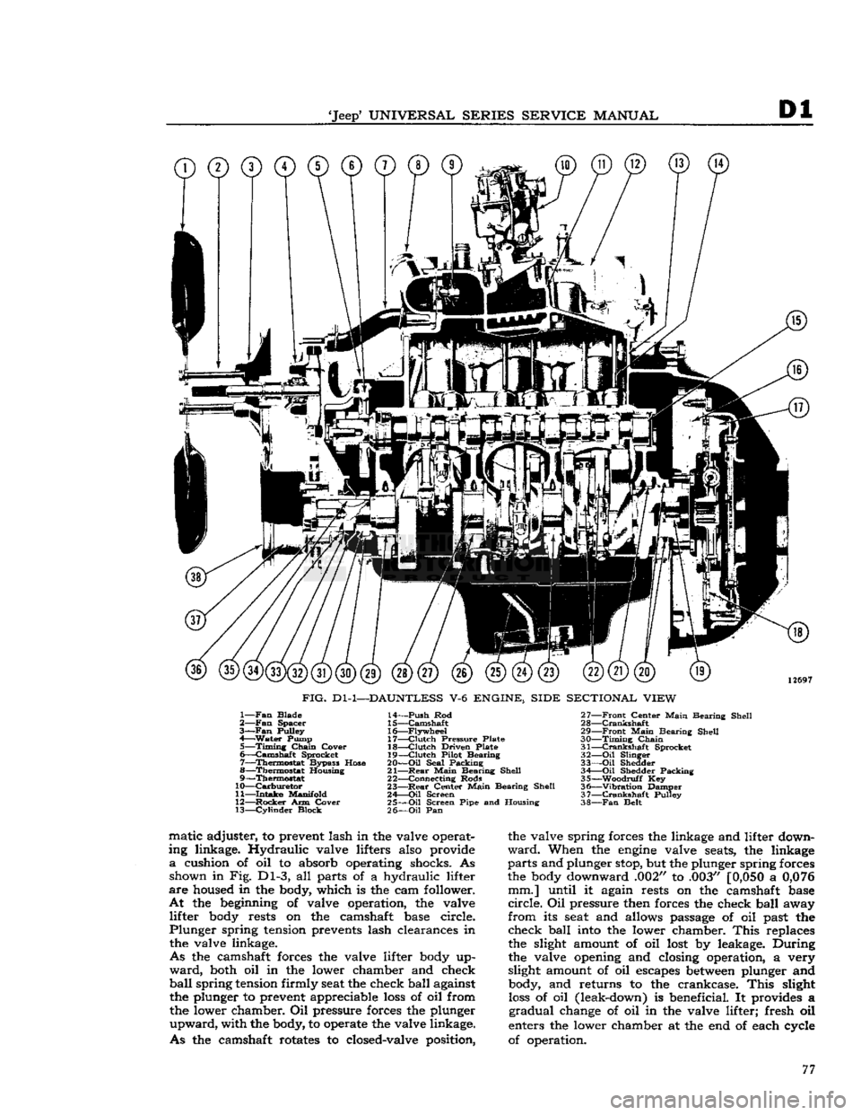
FIG.
Dl-1—DAUNTLESS
V-6
ENGINE, SIDE SECTIONAL VIEW
1—
Fan
Blade
2—
Fan
Spacer
3—Fan
Pulley
4—
Water
Pump 5—
Timing
Chain
Cover
6—
Camshaft
Sprocket
7—
Thermostat
Bypass Hose
8—
Thermostat
Housing
9—
Thermostat
10—
Carburetor
11—
Intake
Manifold
12—
Rocker
Arm Cover 13—
Cylinder
Block 14—
Push
Rod
15—
Camshaft
16—
Flywheel
17—
Clutch
Pressure Plate
18—
Clutch
Driven Plate
19—
Clutch
Pilot Bearing
20—
Oil
Seal Packing
21—
Rear
Main
Bearing Shell
22— Connecting Rods
23—
Rear
Center
Main
Bearing Shell
24—
Oil
Screen
25—
Oil
Screen Pipe and Housing
26—
Oil
Pan 27—
Front
Center
Main
Bearing Shell
28—
Crankshaft
29—
Front
Main
Bearing Shell
30—
Timing
Chain
31—
Crankshaft
Sprocket
32—
Oil
Slinger
33—
Oil
Shedder 34 Oil Shedder Packing
35—
-Woodruff
Key
36—
"Vibration
Damper
37—
Crankshaft
Pulley
38—
Fan
Belt matic adjuster, to prevent lash in the valve operat
ing linkage. Hydraulic valve lifters also provide
a
cushion of oil to absorb operating shocks. As shown in Fig. Dl-3, all parts of a hydraulic lifter
are
housed in the body, which is the cam follower.
At
the beginning of valve operation, the valve lifter body rests on the camshaft base circle.
Plunger
spring tension prevents lash clearances in the valve linkage.
As
the camshaft forces the valve lifter body up
ward,
both oil in the lower chamber and check
ball
spring
tension firmly seat the check ball against the plunger to prevent appreciable
loss
of oil from
the lower chamber. Oil pressure forces the plunger
upward,
with the body, to operate the valve linkage.
As
the camshaft rotates to closed-valve position, the valve spring forces the linkage and lifter down
ward.
When the
engine
valve seats, the linkage
parts
and plunger stop, but the plunger spring forces
the body downward .002" to .003"
[0,050
a
0,076
mm.] until it again rests on the camshaft base
circle.
Oil pressure then forces the check ball away
from
its seat and allows passage of oil past the check ball into the lower chamber.
This
replaces
the slight amount of oil lost by leakage. During
the valve opening and closing operation, a very
slight amount of oil escapes
between
plunger and body, and returns to the crankcase.
This
slight
loss
of oil (leak-down) is beneficial. It provides a
gradual
change of oil in the valve lifter; fresh oil
enters the lower chamber at the end of each cycle
of operation. 77
Page 84 of 376
Dl
DAUNTLESS
V-6
ENGINE
This
will
prevent damage to piston rings or
crack
ing piston lands during removal.
b. Use a silver pencil or quick-drying paint to mark
the cylinder number on all pistons, connecting rods,
and
caps. Starting at the front end of the crankcase,
the cylinders in the right bank are numbered 2-4-6
and
in the
left
bank are numbered
1-3-5.
c. Remove cap and lower connecting rod bearing
half
from No. 1 connecting rod.
d.
Push the piston and rod assembly away from
the crankshaft and remove it from top of cylinder bore. Then install cap and lower bearing half on
connecting rod.
e. Remove each connecting rod and piston as sembly as described in c and d, above.
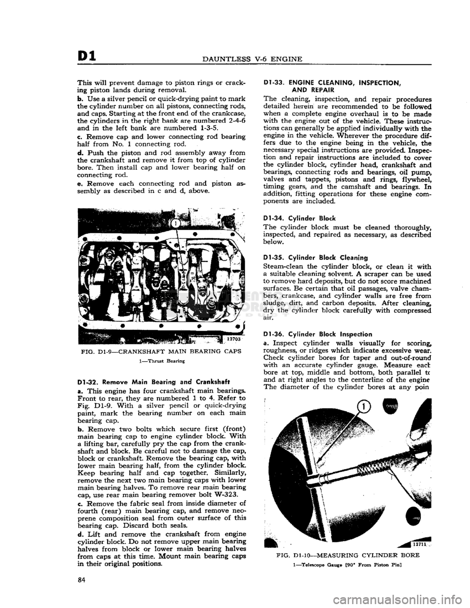
FIG.
D1-9—CRANKSHAFT
MAIN
BEARING
CAPS
1—Thrust
Bearing
D1-32.
Remove
Main
Bearing and Crankshaft
a.
This
engine
has four crankshaft main bearings.
Front
to
rear,
they are numbered 1 to 4. Refer to
Fig.
Dl-9. With a silver pencil or quick-drying
paint, mark the bearing number on each main bearing cap.
b. Remove two
bolts
which secure first (front)
main
bearing cap to
engine
cylinder block. With
a
lifting bar, carefully pry the cap from the crank shaft and block. Be careful not to damage the cap,
block or crankshaft. Remove the bearing cap, with
lower main bearing half, from the cylinder block.
Keep
bearing half and cap
together.
Similarly, remove the next two main bearing caps with lower
main
bearing halves. To remove
rear
main bearing
cap,
use
rear
main bearing remover bolt W-323.
c. Remove the fabric seal from inside diameter of
fourth (rear) main bearing cap, and remove neo-
prene composition seal from outer surface of this
bearing cap. Discard both seals.
d.
Lift
and remove the crankshaft from
engine
cylinder
block. Do not remove upper main bearing
halves from block or lower main bearing halves
from
caps at this time. Mount main bearing caps
in
their original positions.
Dl-33.
ENGINE
CLEANING,
INSPECTION,
AND
REPAIR
The
cleaning, inspection, and repair procedures
detailed herein are recommended to be followed
when a
complete
engine
overhaul is to be made
with the
engine
out of the vehicle. These instruc
tions
can generally be applied individually with the
engine
in the vehicle. Wherever the procedure dif
fers due to the
engine
being in the vehicle, the necessary special instructions are provided. Inspec
tion and repair instructions are included to cover
the cylinder block, cylinder head, crankshaft and bearings, connecting rods and bearings, oil pump,
valves and tappets, pistons and rings, flywheel,
timing gears, and the camshaft and bearings. In
addition, fitting operations for
these
engine
com
ponents
are included.
D1-34.
Cylinder Block
The
cylinder block must be cleaned thoroughly, inspected, and repaired as necessary, as described
below.
Dl-35.
Cylinder Block Cleaning
Steam-clean the cylinder block, or clean it with
a
suitable cleaning solvent A scraper can be used
to remove
hard
deposits, but do not score machined
surfaces. Be certain that oil passages, valve cham
bers,
crankcase, and cylinder walls are free from sludge, dirt, and carbon deposits. After cleaning,
dry
the cylinder block carefully with compressed
air.
Dl-36.
Cylinder Block Inspection
a.
Inspect cylinder walls visually for scoring,
roughness, or ridges which indicate excessive wear.
Check
cylinder bores for taper and out-of-round
with an accurate cylinder
gauge.
Measure eact bore at top, middle and bottom, both parallel tc
and
at right
angles
to the centerline of the
engine
The
diameter of the cylinder bores at any poin
FIG.
Dl-10—MEASURING
CYLINDER
BORE
1—Telescope Gauge [90*
From
Piston Pin]
84