ad blue JEEP COMPASS 2020 Owner handbook (in English)
[x] Cancel search | Manufacturer: JEEP, Model Year: 2020, Model line: COMPASS, Model: JEEP COMPASS 2020Pages: 328, PDF Size: 8.85 MB
Page 72 of 328
GETTING TO KNOW YOUR INSTRUMENT PANEL
70
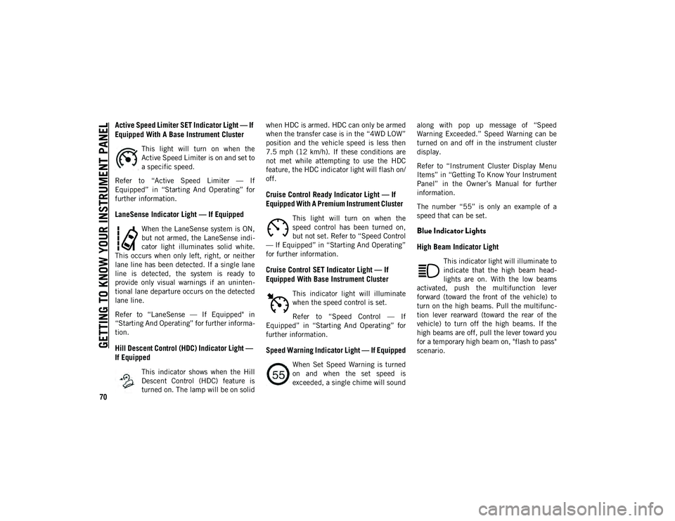
Active Speed Limiter SET Indicator Light — If
Equipped With A Base Instrument Cluster
This light will turn on when the
Active Speed Limiter is on and set to
a specific speed.
Refer to “Active Speed Limiter — If
Equipped” in “Starting And Operating” for
further information.
LaneSense Indicator Light — If Equipped
When the LaneSense system is ON,
but not armed, the LaneSense indi -
cator light illuminates solid white.
This occurs when only left, right, or neither
lane line has been detected. If a single lane
line is detected, the system is ready to
provide only visual warnings if an uninten -
tional lane departure occurs on the detected
lane line.
Refer to “LaneSense — If Equipped" in
“Starting And Operating” for further informa -
tion.
Hill Descent Control (HDC) Indicator Light —
If Equipped
This indicator shows when the Hill
Descent Control (HDC) feature is
turned on. The lamp will be on solid when HDC is armed. HDC can only be armed
when the transfer case is in the “4WD LOW”
position and the vehicle speed is less then
7.5 mph (12 km/h). If these conditions are
not met while attempting to use the HDC
feature, the HDC indicator light will flash on/
off.
Cruise Control Ready Indicator Light — If
Equipped With A Premium Instrument Cluster
This light will turn on when the
speed control has been turned on,
but not set. Refer to “Speed Control
— If Equipped” in “Starting And Operating”
for further information.
Cruise Control SET Indicator Light — If
Equipped With Base Instrument Cluster
This indicator light will illuminate
when the speed control is set.
Refer to “Speed Control — If
Equipped” in “Starting And Operating” for
further information.
Speed Warning Indicator Light — If Equipped
When Set Speed Warning is turned
on and when the set speed is
exceeded, a single chime will sound along with pop up message of “Speed
Warning Exceeded.” Speed Warning can be
turned on and off in the instrument cluster
display.
Refer to “Instrument Cluster Display Menu
Items” in “Getting To Know Your Instrument
Panel” in the Owner’s Manual for further
information.
The number “55” is only an example of a
speed that can be set.
Blue Indicator Lights
High Beam Indicator Light
This indicator light will illuminate to
indicate that the high beam head
-
lights are on. With the low beams
activated, push the multifunction lever
forward (toward the front of the vehicle) to
turn on the high beams. Pull the multifunc -
tion lever rearward (toward the rear of the
vehicle) to turn off the high beams. If the
high beams are off, pull the lever toward you
for a temporary high beam on, "flash to pass"
scenario.
2020_JEEP_M6_UG_UK.book Page 70
Page 170 of 328
STARTING AND OPERATING
168
(Continued)
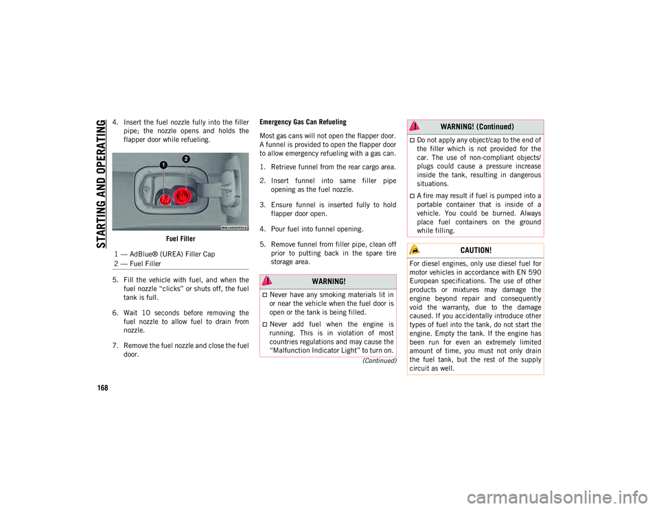
4. Insert the fuel nozzle fully into the fillerpipe; the nozzle opens and holds the
flapper door while refueling.
Fuel Filler
5. Fill the vehicle with fuel, and when the fuel nozzle “clicks” or shuts off, the fuel
tank is full.
6. Wait 10 seconds before removing the fuel nozzle to allow fuel to drain from
nozzle.
7. Remove the fuel nozzle and close the fuel door. Emergency Gas Can Refueling
Most gas cans will not open the flapper door.
A funnel is provided to open the flapper door
to allow emergency refueling with a gas can.
1. Retrieve funnel from the rear cargo area.
2. Insert funnel into same filler pipe
opening as the fuel nozzle.
3. Ensure funnel is inserted fully to hold flapper door open.
4. Pour fuel into funnel opening.
5. Remove funnel from filler pipe, clean off prior to putting back in the spare tire
storage area.
1 — AdBlue® (UREA) Filler Cap
2 — Fuel Filler
WARNING!
Never have any smoking materials lit in
or near the vehicle when the fuel door is
open or the tank is being filled.
Never add fuel when the engine is
running. This is in violation of most
countries regulations and may cause the
“Malfunction Indicator Light” to turn on.
Do not apply any object/cap to the end of
the filler which is not provided for the
car. The use of non-compliant objects/
plugs could cause a pressure increase
inside the tank, resulting in dangerous
situations.
A fire may result if fuel is pumped into a
portable container that is inside of a
vehicle. You could be burned. Always
place fuel containers on the ground
while filling.
CAUTION!
For diesel engines, only use diesel fuel for
motor vehicles in accordance with EN 590
European specifications. The use of other
products or mixtures may damage the
engine beyond repair and consequently
void the warranty, due to the damage
caused. If you accidentally introduce other
types of fuel into the tank, do not start the
engine. Empty the tank. If the engine has
been run for even an extremely limited
amount of time, you must not only drain
the fuel tank, but the rest of the supply
circuit as well.
WARNING! (Continued)
2020_JEEP_M6_UG_UK.book Page 168
Page 171 of 328
169
AdBlue® (UREA) — If Equipped
The vehicle is equipped with an UREA injec -
tion system and Selective Catalytic Reduc -
tion to meet emission standards. These two
systems ensure compliance with the diesel
emissions requirements; at the same time,
they ensure fuel-efficiency, handling, torque
and power. For messages and system warn -
ings, refer to the "Warning Lights And
Messages" in the "Getting To Know Your
Instrument Panel" section. AdBlue® (UREA)
is a very stable product with a long shelf life.
Stored at temperatures LOWER than 90°F
(32°C), it has a shelf life of at least one year.
For more information on the AdBlue® liquid
type, see the “Fluids and lubricants” in the
“Technical specifications” section. The
vehicle is equipped with an automatic
AdBlue® heating system when the engine
starts allowing the system to work correctly
at temperatures lower than 12°F (-11°C).
NOTE:
AdBlue® freezes at temperatures lower than
12 °F (-11 °C).
AdBlue® (UREA) Storage
AdBlue® (UREA) is considered a very stable
product with a long shelf life. If AdBlue®
(UREA) is kept in temperatures between 10°
and 90°F (-12° and 32°C), it will last a
minimum of one year.
AdBlue® (UREA) is subject to freezing at the
lowest temperatures. For example, AdBlue®
(UREA) may freeze at temperatures at or
below 12°F (-11°C). The system has been
designed to operate in this environment.
NOTE:
When working with AdBlue® (UREA), it is
important to know that:
Any containers or parts that come into
contact with AdBlue® (UREA) must be
AdBlue® (UREA) compatible (plastic or
stainless steel). Copper, brass, aluminum,
iron or non-stainless steel should be
avoided as they are subject to corrosion by
AdBlue® (UREA).
If AdBlue® (UREA) is spilled, it should be
wiped up completely.
Adding AdBlue® (UREA)
Preliminary Conditions
AdBlue® (UREA) freezes at temperatures
lower than 12°F (-11°C). If the car stands for
a long time at this temperature refilling
could be difficult. For this reason, it is
advised to park the vehicle in a garage and/
or heated environment and wait for the urea
to return to liquid state before topping up.
Proceed as follows:
Park the car on flat ground and stop the
engine by cycling the ignition to the OFF
position.
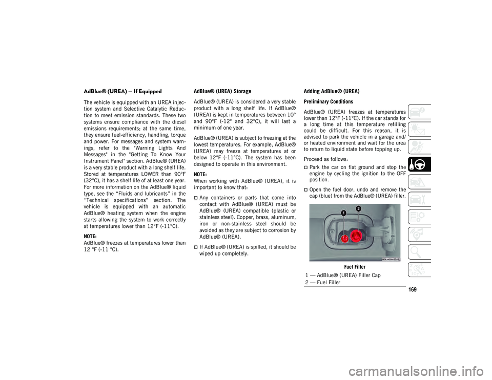
Open the fuel door, undo and remove the
cap (blue) from the AdBlue® (UREA) filler.
Fuel Filler
1 — AdBlue® (UREA) Filler Cap
2 — Fuel Filler
2020_JEEP_M6_UG_UK.book Page 169
Page 172 of 328
STARTING AND OPERATING
170
Refilling With Nozzles
You can fill up at any AdBlue® (UREA)
distributor.
Proceed as follows:
Insert the AdBlue® (UREA) nozzle in the
filler, start refilling and stop refilling at the
first shut-off (the shut-off indicates that
the AdBlue® (UREA) tank is full). Do not
proceed with the refilling, to prevent
spillage of AdBlue® (UREA).
Extract the nozzle.
Refilling With Containers
Proceed as follows:
Check the expiration date.
Read the advice for use on the label before
pouring the content of the bottle into the
AdBlue® (UREA) tank.
If systems which cannot be screwed in
(e.g. tanks) are used for refilling, after the
indication appears on the instrument
panel display refer to “Warning lights And
Messages" in the “Getting To Know Your
Instrument Panel” for further information,
fill the AdBlue® (UREA) tank with no
more than 2 Gallons (8 liters).
If containers which can be screwed to the
filler are used, the reservoir is full when
the AdBlue® (UREA) level in the
container stops pouring out. Do not
proceed further.
Operations After Refilling
Proceed as follows:
Fit the cap back on the AdBlue® (UREA)
filler by turning it clockwise and screwing
it completely.
Cycle the ignition to RUN (it is not neces-
sary to start the engine).
Wait for the indication on the instrument
panel to switch off before moving the car.
The indication may stay on for a few
seconds to approximately half a minute. If
the engine is started and the car is moved,
the indication will remain on for longer.
This will not compromise engine opera-
tion.
If the AdBlue® (UREA) was topped up
when the tank was empty, wait for
2 minutes before starting the engine. NOTE:
If AdBlue® (UREA) is spilled out of the
filler neck, clean up well the area and
proceed to filling up again. If the liquid
crystallizes, eliminate it with a sponge and
warm water.
DO NOT EXCEED THE MAXIMUM LEVEL:
this could cause damage to the reservoir.
AdBlue® (UREA) freezes at under 12°F
(-11°C). Although the system is designed
to operate below the freezing point of the
UREA, it is advisable not to fill the tank
beyond the maximum level because if the
UREA freezes the system can be
damaged. Follow the instructions in this
section.
If the AdBlue® (UREA) is spilled on
painted surfaces or aluminium, immedi
-
ately clean the area with water and use
absorbent material to collect the fluid that
has been spilled on the ground.
Do not try to start the engine if AdBlue®
(UREA) was accidentally added to the
diesel fuel tank, this can result in serious
engine damage, contact an authorized
dealer.
2020_JEEP_M6_UG_UK.book Page 170
Page 173 of 328
171
Do not add additives or other fluids to
AdBlue® (UREA), doing so could damage
the system.
The use of non-conforming or degraded
AdBlue® (UREA) may lead to indications
appearing on the instrument panel display
refer to “Warning Lights And Messages" in
the “Getting To Know Your Instrument
Panel” for further information.
Never pour AdBlue® (UREA) into another
container: it could be contaminated.
If the AdBlue® (UREA) runs out, see refer
to “Warning Lights And Messages" in the
“Getting To Know Your Instrument Panel”
for further information to continue using
the car normally.
VEHICLE LOADING
Certification Label
As required by local traffic regulations, your
vehicle has a certification label affixed to the
driver's side door or pillar.
Refer to “Tire Safety” in “Servicing And
Maintenance” for further informationThis label contains the month and year of
manufacture, Gross Vehicle Weight Rating
(GVWR), Gross Axle Weight Rating (GAWR)
front and rear, and Vehicle Identification
Number (VIN). A Month-Day-Hour (MDH)
number is included on this label and indi
-
cates the Month, Day and Hour of manufac -
ture. The bar code that appears on the
bottom of the label is your VIN.
TRAILER TOWING
Common Towing Definitions
The following trailer towing related defini -
tions will assist you in understanding the
following information:
Gross Vehicle Weight Rating (GVWR)
The GVWR is the total allowable weight of
your vehicle. This includes driver, passen -
gers, cargo and tongue weight. The total load
must be limited so that you do not exceed
the GVWR. Refer to “Vehicle Loading/Vehicle
Certification Label” in “Starting And Oper -
ating” for further information.
Gross Trailer Weight (GTW)
The GTW is the weight of the trailer plus the
weight of all cargo, consumables and equip -
ment (permanent or temporary) loaded in or
on the trailer in its "loaded and ready for
operation" condition.
The recommended way to measure GTW is to
put your fully loaded trailer on a vehicle
scale. The entire weight of the trailer must be
supported by the scale.
Gross Axle Weight Rating (GAWR)
The GAWR is the maximum capacity of the
front and rear axles. Distribute the load over
the front and rear axles evenly. Make sure
that you do not exceed either front or rear
GAWR. Refer to “Vehicle Loading/Vehicle
Certification Label” in “Starting And Oper -
ating” for further information.
WARNING!
It is important that you do not exceed the
maximum front or rear GAWR. A dangerous
driving condition can result if either rating
is exceeded. You could lose control of the
vehicle and have a collision.
2020_JEEP_M6_UG_UK.book Page 171
Page 181 of 328
179
High Intensity Discharge (HID)
Headlamps — If Equipped
The headlamps contain a type of high voltage
discharge light source. High voltage can
remain in the circuit even with the headlamp
switch off. Because of this, you should not
attempt to service a HID headlamp light
source yourself. If an HID headlamp light
source fails, take your vehicle to an autho-
rized dealer for service.
NOTE:
On vehicles equipped with HID headlamps,
when the headlamps are turned on, there is
a blue hue to the lights. This diminishes and
becomes more white after approximately 10
seconds, as the system charges.
Replacing Exterior Bulbs
Headlamps
Hi/Lo Beam Light Halogen
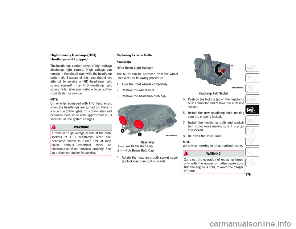
The bulbs can be accessed from the wheel
liner with the following procedure:
1. Turn the front wheels completely.
2. Remove the wheel liner.
3. Remove the headlamp bulb cap.
Headlamp
4. Rotate the headlamp bulb socket coun -
terclockwise then pull outwards. Headlamp Bulb Socket
5. Push on the locking tab on the headlamp bulb connector and remove the bulb and
socket.
6. Install the new headlamp bulb making sure it’s properly locked.
7. Install the headlamp bulb and socket; turn it clockwise making sure it is prop -
erly locked.
8. Reinstall the wheel liner.
NOTE:
We advise referring to an authorized dealer.
WARNING!
A transient high voltage occurs at the bulb
sockets of HID headlamps when the
headlamp switch is turned ON. It may
cause serious electrical shock or
electrocution if not serviced properly. See
an authorized dealer for service.
1 — Low Beam Bulb Cap
2 — High Beam Bulb Cap
WARNING!
Carry out the operation of replacing lamps
only with the engine off. Also make sure
that the engine is cold, to avoid the danger
of burns.
2020_JEEP_M6_UG_UK.book Page 179
Page 185 of 328
183
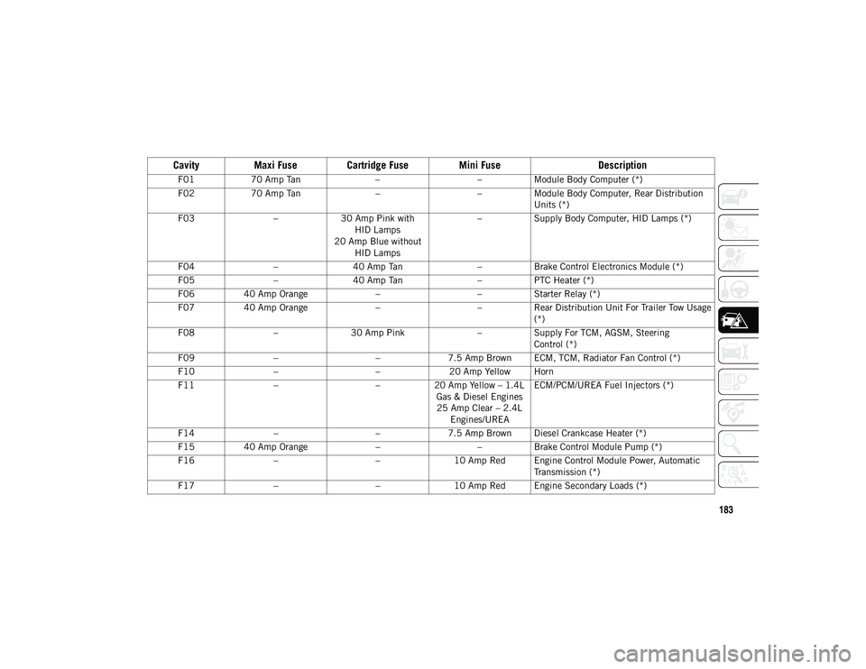
Cavity
Maxi Fuse Cartridge Fuse Mini Fuse Description
F0170 Amp Tan ––Module Body Computer (*)
F02 70 Amp Tan ––Module Body Computer, Rear Distribution
Units (*)
F03 –30 Amp Pink with
HID Lamps
20 Amp Blue without HID Lamps –
Supply Body Computer, HID Lamps (*)
F04 –40 Amp Tan –Brake Control Electronics Module (*)
F05 –40 Amp Tan –PTC Heater (*)
F06 40 Amp Orange ––Starter Relay (*)
F07 40 Amp Orange ––Rear Distribution Unit For Trailer Tow Usage
(*)
F08 –30 Amp Pink –Supply For TCM, AGSM, Steering
Control (*)
F09 – –7.5 Amp Brown ECM, TCM, Radiator Fan Control (*)
F10 – –20 Amp Yellow Horn
F11 – –20 Amp Yellow – 1.4L
Gas & Diesel Engines25 Amp Clear – 2.4L Engines/UREA ECM/PCM/UREA Fuel Injectors (*)
F14 – –7.5 Amp Brown Diesel Crankcase Heater (*)
F15 40 Amp Orange ––Brake Control Module Pump (*)
F16 – –10 Amp Red Engine Control Module Power, Automatic
Transmission (*)
F17 – –10 Amp Red Engine Secondary Loads (*)
2020_JEEP_M6_UG_UK.book Page 183
Page 186 of 328
IN CASE OF EMERGENCY
184
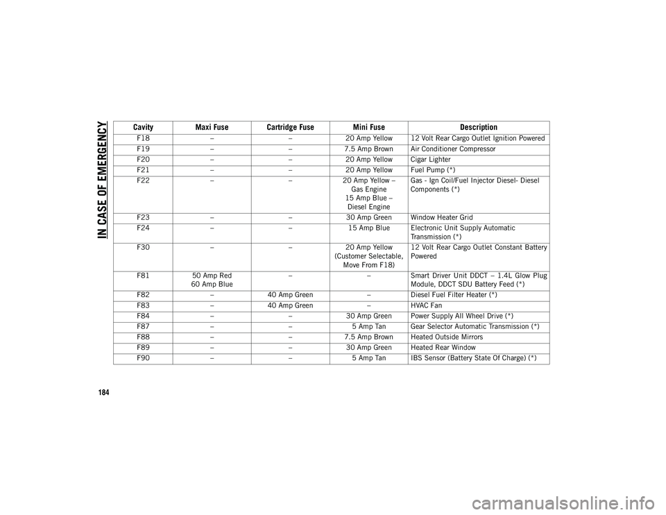
F18– –20 Amp Yellow 12 Volt Rear Cargo Outlet Ignition Powered
F19 – –7.5 Amp Brown Air Conditioner Compressor
F20 – –20 Amp Yellow Cigar Lighter
F21 – –20 Amp Yellow Fuel Pump (*)
F22 – –20 Amp Yellow –
Gas Engine
15 Amp Blue – Diesel Engine Gas - Ign Coil/Fuel Injector Diesel- Diesel
Components (*)
F23 – –30 Amp Green Window Heater Grid
F24 – –15 Amp Blue Electronic Unit Supply Automatic
Transmission (*)
F30 – –20 Amp Yellow
(Customer Selectable, Move From F18) 12 Volt Rear Cargo Outlet Constant Battery
Powered
F81 50 Amp Red
60 Amp Blue –
–Smart Driver Unit DDCT – 1.4L Glow Plug
Module, DDCT SDU Battery Feed (*)
F82 –40 Amp Green –Diesel Fuel Filter Heater (*)
F83 –40 Amp Green –HVAC Fan
F84 – –30 Amp Green Power Supply All Wheel Drive (*)
F87 – –5 Amp Tan Gear Selector Automatic Transmission (*)
F88 – –7.5 Amp Brown Heated Outside Mirrors
F89 – –30 Amp Green Heated Rear Window
F90 – –5 Amp Tan IBS Sensor (Battery State Of Charge) (*)
CavityMaxi Fuse Cartridge Fuse Mini Fuse Description
2020_JEEP_M6_UG_UK.book Page 184
Page 187 of 328
185
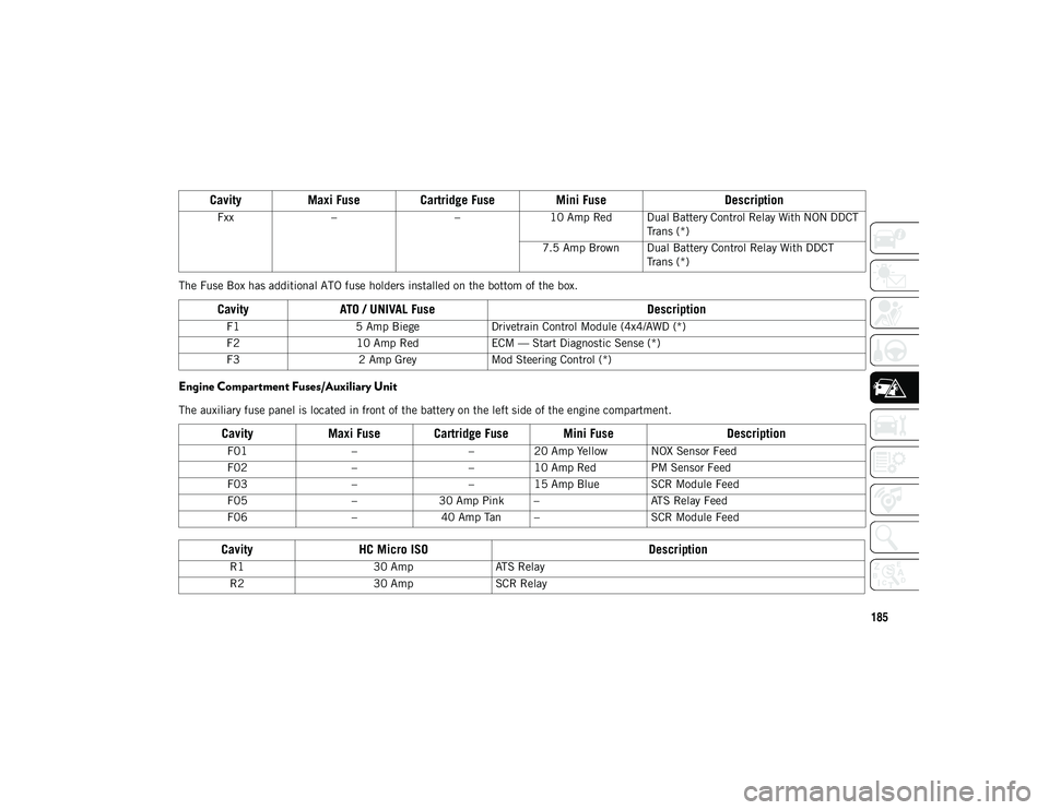
The Fuse Box has additional ATO fuse holders installed on the bottom of the box.
Engine Compartment Fuses/Auxiliary Unit
The auxiliary fuse panel is located in front of the battery on the left side of the engine compartment.Fxx
– –10 Amp Red Dual Battery Control Relay With NON DDCT
Trans (*)
7.5 Amp Brown Dual Battery Control Relay With DDCT Trans (*)
Cavity ATO / UNIVAL Fuse Description
F15 Amp Biege Drivetrain Control Module (4x4/AWD (*)
F2 10 Amp Red ECM — Start Diagnostic Sense (*)
F3 2 Amp Grey Mod Steering Control (*)
CavityMaxi Fuse Cartridge Fuse Mini Fuse Description
F01––20 Amp Yellow NOX Sensor Feed
F02 ––10 Amp Red PM Sensor Feed
F03 ––15 Amp Blue SCR Module Feed
F05 –30 Amp Pink – ATS Relay Feed
F06 –40 Amp Tan – SCR Module Feed
CavityHC Micro ISO Description
R130 AmpATS Relay
R2 30 AmpSCR Relay
CavityMaxi Fuse Cartridge Fuse Mini Fuse Description
2020_JEEP_M6_UG_UK.book Page 185
Page 189 of 328
187
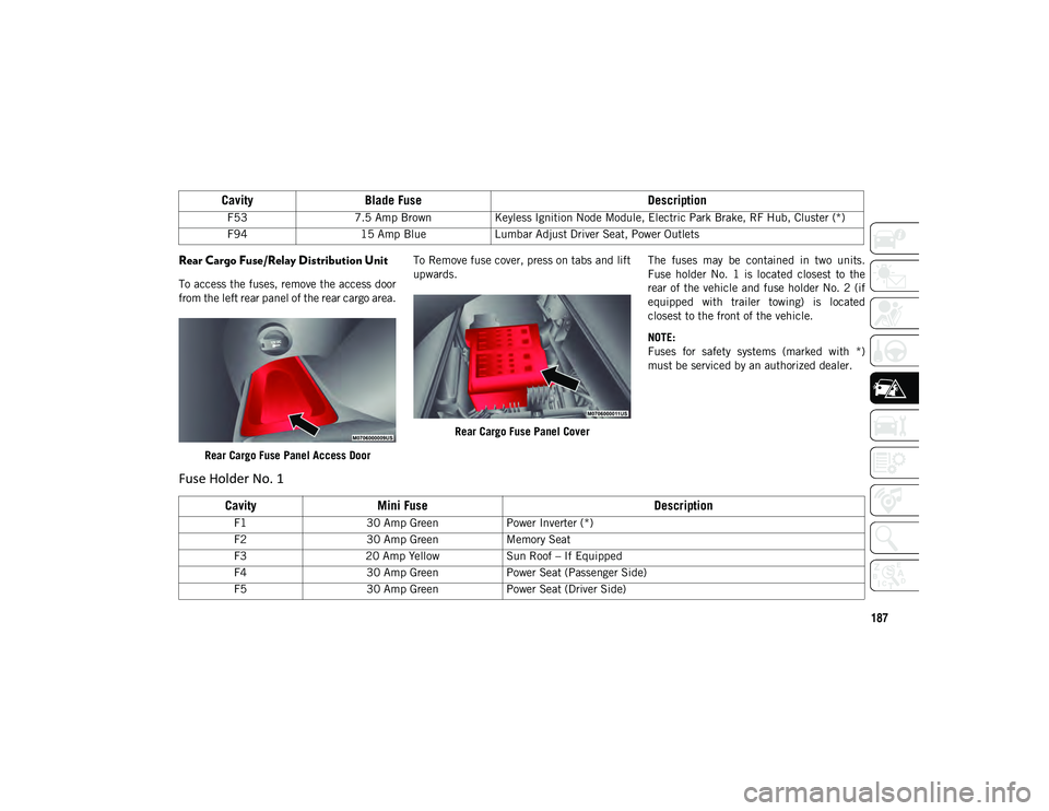
Rear Cargo Fuse/Relay Distribution Unit
To access the fuses, remove the access door
from the left rear panel of the rear cargo area.Rear Cargo Fuse Panel Access Door To Remove fuse cover, press on tabs and lift
upwards.
Rear Cargo Fuse Panel Cover The fuses may be contained in two units.
Fuse holder No. 1 is located closest to the
rear of the vehicle and fuse holder No. 2 (if
equipped with trailer towing) is located
closest to the front of the vehicle.
NOTE:
Fuses for safety systems (marked with *)
must be serviced by an authorized dealer.
F53
7.5 Amp Brown Keyless Ignition Node Module, Electric Park Brake, RF Hub, Cluster (*)
F94 15 Amp Blue Lumbar Adjust Driver Seat, Power Outlets
CavityBlade Fuse Description
Fuse Holder No. 1
CavityMini Fuse Description
F130 Amp Green Power Inverter (*)
F2 30 Amp Green Memory Seat
F3 20 Amp Yellow Sun Roof – If Equipped
F4 30 Amp Green Power Seat (Passenger Side)
F5 30 Amp Green Power Seat (Driver Side)
2020_JEEP_M6_UG_UK.book Page 187