stop start JEEP GLADIATOR 2023 Owners Manual
[x] Cancel search | Manufacturer: JEEP, Model Year: 2023, Model line: GLADIATOR, Model: JEEP GLADIATOR 2023Pages: 448, PDF Size: 17.37 MB
Page 6 of 448

4
INSTRUMENT CLUSTER DISPLAY ...................... 121 Instrument Cluster Display Location And
Controls .......................................................... 122
Oil Life Reset — If Equipped
S
................... 122
Off Road+ Display — If Equipped .................. 123
Instrument Cluster Display Selectable
Items .............................................................. 123
Instrument Cluster Display Menu Items ...... 124
Battery Saver On, Battery Saver Mode
Message, And Electrical Load Reduction
Actions
(If Equipped) .................................................. 127
Diesel Displays .............................................. 128 Diesel Particulate Filter (DPF) Messages .... 128Fuel System Messages ................................. 130
WARNING LIGHTS AND MESSAGES ................. 132
Red Warning Lights ....................................... 132
Yellow Warning Lights ................................... 135Yellow Indicator Lights .................................. 138
Green Indicator Lights................................... 139White Indicator Lights ................................... 140Blue Indicator Lights ..................................... 141
ONBOARD DIAGNOSTIC SYSTEM — OBD II ...... 141
Onboard Diagnostic System
(OBD II) Cybersecurity ................................... 142
EMISSIONS INSPECTION AND MAINTENANCE
PROGRAMS .......................................................... 142
STARTING AND OPERATING
STARTING THE ENGINE — GASOLINE ENGINE
(IF EQUIPPED) ...................................................... 144
Manual Transmission — If Equipped ........... 144Automatic Transmission —
If Equipped .................................................... 144
Normal Starting ............................................ 144
AutoPark ........................................................ 145Extreme Cold Weather
(Below –22°F Or −30°C) ............................ 146
Extended Park Starting ................................. 146
If Engine Fails To Start ................................. 147
After Starting ................................................. 147
STARTING THE ENGINE — DIESEL ENGINE
(IF EQUIPPED) ...................................................... 147
Automatic Transmission ............................... 148
Extreme Cold Weather .................................. 148
Normal Starting ............................................. 148Starting Fluids ............................................... 149
NORMAL OPERATION — DIESEL ENGINE ......... 149
Cold Weather Precautions ............................ 149
Engine Idling .................................................. 150
Stopping The Engine ..................................... 150
Cooling System Tips — Automatic
Transmission ................................................. 151
ENGINE BREAK-IN RECOMMENDATIONS —
GASOLINE ENGINE (IF EQUIPPED) ................... 151 ENGINE BREAK-IN RECOMMENDATIONS —
DIESEL ENGINE (IF EQUIPPED) .......................... 152
PARKING BRAKE ................................................. 152
MANUAL TRANSMISSION — IF EQUIPPED ....... 153
Shifting........................................................... 154
Downshifting.................................................. 155
AUTOMATIC TRANSMISSION —
IF EQUIPPED ......................................................... 155
Ignition Park Interlock................................... 156
Brake/Transmission Shift Interlock (BTSI)
System .......................................................... 1578–Speed Automatic Transmission .............. 157
Gear Ranges .................................................. 157
FOUR–WHEEL DRIVE OPERATION ................... 161
Four-Position Transfer Case —
If Equipped .................................................... 161
Five-Position Transfer Case —
If Equipped .................................................... 163
Trac-Lok Rear Axle — If Equipped ................ 165Axle Lock (Tru-Lok) Front And Rear —
If Equipped ................................................... 165
Axle Lock (Tru-Lok) Rear Only —
If Equipped ................................................... 166
Electronic Sway Bar Disconnect —
If Equipped ................................................... 166
OFF ROAD+ — If Equipped ............................ 168
ELECTRO-HYDRAULIC POWER STEERING ....... 168
23_JT_OM_EN_USC_t.book Page 4
Page 7 of 448

5
STOP/START SYSTEM — AUTOMATIC
TRANSMISSION (IF EQUIPPED) ........................ 169 Autostop Mode .............................................. 169Possible Reasons The Engine Does Not
Autostop ......................................................... 170
To Start The Engine While In Autostop
Mode .............................................................. 170
To Manually Turn Off The Stop/Start
System ........................................................... 171To Manually Turn On The Stop/Start
System ........................................................... 171System Malfunction ...................................... 171
STOP/START SYSTEM — MANUAL
TRANSMISSION (IF EQUIPPED) .........................171
Autostop Mode .............................................. 172Possible Reasons The Engine Does Not
Autostop ......................................................... 172
To Start The Engine While In Autostop
Mode .............................................................. 172
To Manually Turn Off The Stop/Start
System ........................................................... 173To Manually Turn On The Stop/Start
System ........................................................... 173System Malfunction ...................................... 173
CRUISE CONTROL SYSTEMS —
IF EQUIPPED ........................................................ 173
Cruise Control ............................................... 173
Adaptive Cruise Control (ACC) ...................... 175 PARKSENSE FRONT/REAR PARK ASSIST
SYSTEM — IF EQUIPPED .................................... 184
ParkSense Sensors ....................................... 184
ParkSense Warning Display ......................... 184
ParkSense Display ........................................ 184Enabling And Disabling ParkSense .............. 187Service The ParkSense Park Assist
System ........................................................... 187
Cleaning The ParkSense System ................. 187
ParkSense System Usage Precautions........ 188
PARKVIEW REAR BACK UP CAMERA............... 189
TRAILCAM SYSTEM — IF EQUIPPED ................ 190
REFUELING THE VEHICLE — GASOLINE
ENGINE (IF EQUIPPED) ....................................... 191 Fuel Filler Cap................................................ 191Loose Fuel Filler Cap Message ................... 192
REFUELING THE VEHICLE — DIESEL ENGINE
(IF EQUIPPED) ..................................................... 192
Avoid Using Contaminated Fuel ................... 193Bulk Fuel Storage — Diesel Fuel................... 193Diesel Exhaust Fluid ..................................... 193
VEHICLE LOADING .............................................. 195
Certification Label ......................................... 195
TRAILER TOWING ............................................... 197
Common Towing Definitions......................... 197
Trailer Hitch Classification ............................ 199
Trailer Towing Weights (Maximum Trailer
Weight Ratings) ............................................ 199
Trailer And Tongue Weight............................ 202
Towing Requirements ................................... 202Towing Tips .................................................... 204 RECREATIONAL TOWING (BEHIND
MOTORHOME) ...................................................... 205
Towing This Vehicle Behind Another
Vehicle ........................................................... 205
Recreational Towing — Four-Wheel Drive
Models ........................................................... 205
DRIVING TIPS ....................................................... 207
On-Road Driving Tips..................................... 207Off-Road Driving Tips .................................... 207
MULTIMEDIA
UCONNECT SYSTEMS ......................................... 214
CYBERSECURITY ................................................. 214
UCONNECT SETTINGS ......................................... 215 Customer Programmable Features ............. 215
UCONNECT INTRODUCTION................................ 230
System Overview .......................................... 230Drag & Drop Menu Bar ................................. 232
Safety And General Information................... 232
UCONNECT MODES ............................................. 233
Steering Wheel Audio Controls .................... 233
Radio Mode .................................................. 234Media Mode ................................................. 242
Phone Mode ................................................. 244
ANDROID AUTO™ & APPLE CARPLAY® —
IF EQUIPPED ......................................................... 254
Android Auto™
S
........................................ 254
Apple CarPlay®
S
....................................... 256
Android Auto™ And Apple CarPlay® Tips
And Tricks ...................................................... 258
23_JT_OM_EN_USC_t.book Page 5
Page 14 of 448
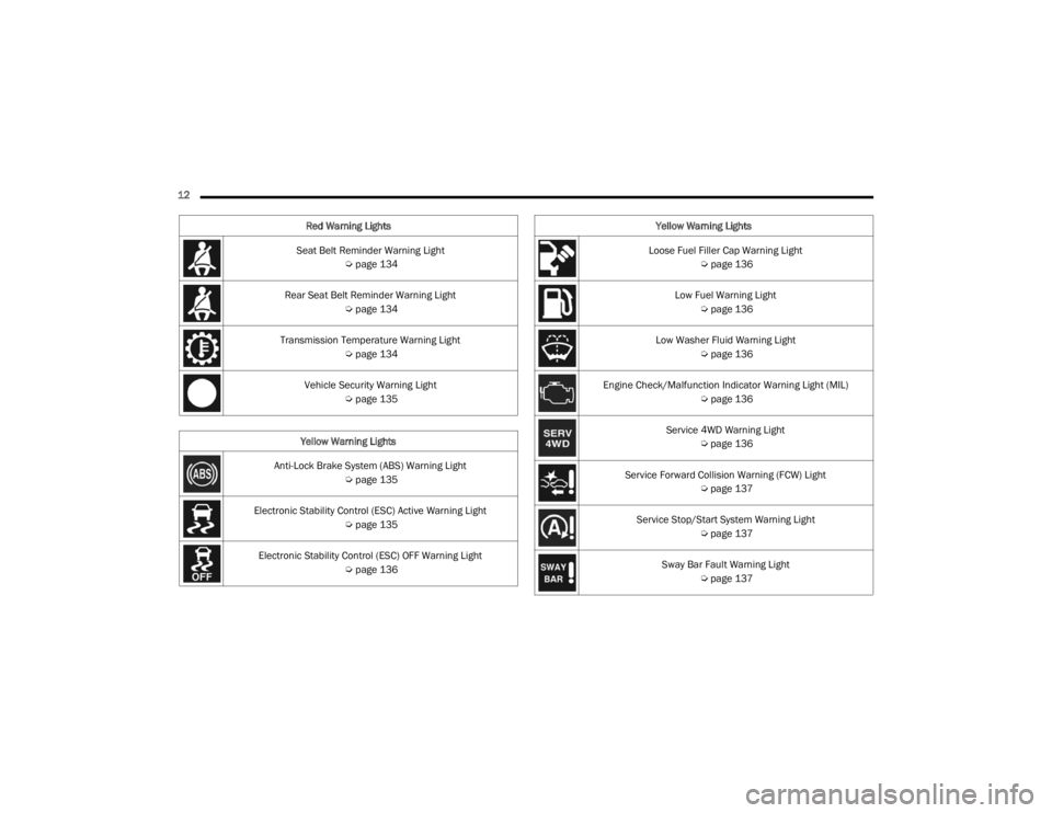
12 Seat Belt Reminder Warning Light Úpage 134
Rear Seat Belt Reminder Warning Light Úpage 134
Transmission Temperature Warning Light Úpage 134
Vehicle Security Warning Light Úpage 135
Yellow Warning Lights
Anti-Lock Brake System (ABS) Warning Light Úpage 135
Electronic Stability Control (ESC) Active Warning Light Úpage 135
Electronic Stability Control (ESC) OFF Warning Light Úpage 136
Red Warning Lights
Loose Fuel Filler Cap Warning Light
Úpage 136
Low Fuel Warning Light Úpage 136
Low Washer Fluid Warning Light Úpage 136
Engine Check/Malfunction Indicator Warning Light (MIL) Úpage 136
Service 4WD Warning Light Úpage 136
Service Forward Collision Warning (FCW) Light Úpage 137
Service Stop/Start System Warning Light Úpage 137
Sway Bar Fault Warning Light Úpage 137
Yellow Warning Lights
23_JT_OM_EN_USC_t.book Page 12
Page 16 of 448
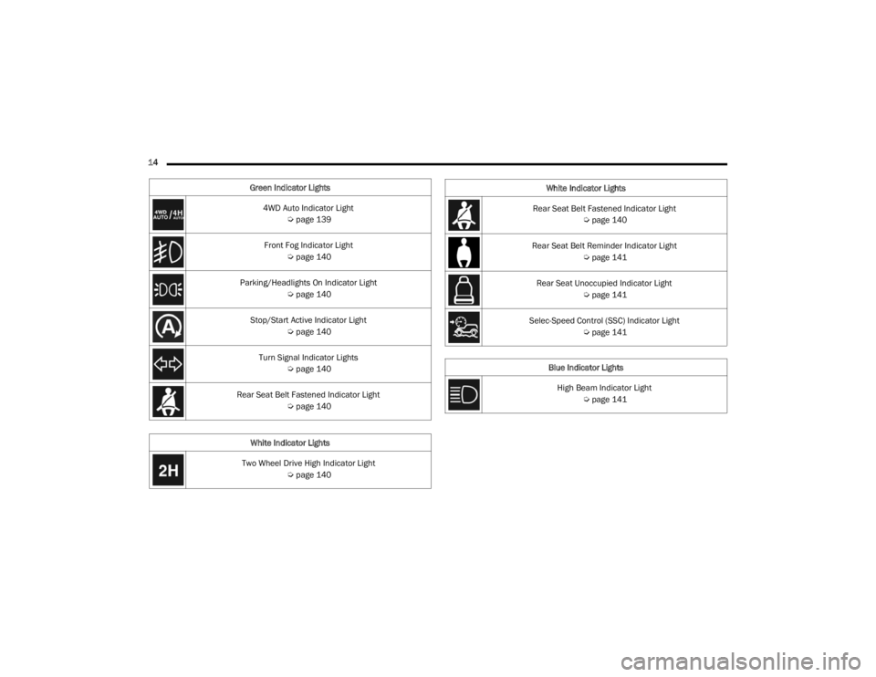
14 Green Indicator Lights4WD Auto Indicator Light Úpage 139
Front Fog Indicator Light Úpage 140
Parking/Headlights On Indicator Light Úpage 140
Stop/Start Active Indicator Light Úpage 140
Turn Signal Indicator Lights Úpage 140
Rear Seat Belt Fastened Indicator Light Úpage 140
White Indicator Lights
Two Wheel Drive High Indicator Light Úpage 140
Rear Seat Belt Fastened Indicator Light
Úpage 140
Rear Seat Belt Reminder Indicator Light Úpage 141
Rear Seat Unoccupied Indicator Light Úpage 141
Selec-Speed Control (SSC) Indicator Light Úpage 141
Blue Indicator Lights High Beam Indicator Light Úpage 141
White Indicator Lights
23_JT_OM_EN_USC_t.book Page 14
Page 19 of 448
GETTING TO KNOW YOUR VEHICLE17
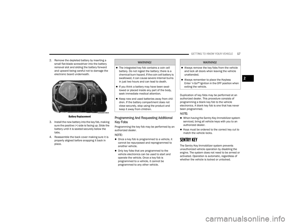
2. Remove the depleted battery by inserting a small flat-blade screwdriver into the battery
removal slot and sliding the battery forward
and upward being careful not to damage the
electronic board underneath.
Battery Replacement
3. Install the new battery into the key fob, making sure the positive (+) side is facing up. Slide the
battery until it is seated securely below the
tabs.
4. Reassemble the back cover making sure it is properly aligned before snapping it back in
place.
Programming And Requesting Additional
Key Fobs
Programming the key fob may be performed by an
authorized dealer.
NOTE:
Once a key fob is programmed to a vehicle, it
cannot be repurposed and reprogrammed to
another vehicle.
Only key fobs that are programmed to the
vehicle electronics can be used to start and
operate the vehicle. Once a key fob is
programmed to a vehicle, it cannot be
programmed to any other vehicle. Duplication of key fobs may be performed at an
authorized dealer. This procedure consists of
programming a blank key fob to the vehicle
electronics. A blank key fob is one that has never
been programmed.
NOTE:
When having the Sentry Key Immobilizer system
serviced, bring all vehicle keys with you to an
authorized dealer.
Keys must be ordered to the correct key cut to
match the vehicle locks.
SENTRY KEY
The Sentry Key Immobilizer system prevents
unauthorized vehicle operation by disabling the
engine. The system does not need to be armed or
activated. Operation is automatic, regardless of
whether the vehicle is locked or unlocked.
WARNING!
The integrated key fob contains a coin cell
battery. Do not ingest the battery; there is a
chemical burn hazard. If the coin cell battery is
swallowed, it can cause severe internal burns
in just two hours and can lead to death.
If you think a battery may have been swal-
lowed or placed inside any part of the body,
seek immediate medical attention.
Keep new and used batteries away from chil
-
dren. If the battery compartment does not
close securely, stop using the product and
keep it away from children.
WARNING!
Always remove the key fobs from the vehicle
and lock all doors when leaving the vehicle
unattended.
Always remember to place the Keyless
Enter ‘n Go™ Ignition in the OFF position when
exiting the vehicle.2
23_JT_OM_EN_USC_t.book Page 17
Page 20 of 448
18GETTING TO KNOW YOUR VEHICLE
The system uses a key fob, keyless push button
ignition and a Radio Frequency (RF) receiver to
prevent unauthorized vehicle operation. Therefore,
only key fobs that are programmed to the vehicle
can be used to start and operate the vehicle. The
system cannot reprogram a key fob obtained from
another vehicle.
After placing the ignition switch in the ON/RUN
position, the Vehicle Security Light will turn on for
three seconds for a bulb check. If the light remains
on after the bulb check, it indicates that there is a
problem with the electronics. In addition, if the light
begins to flash after the bulb check, it indicates
that someone attempted to start the engine with
an invalid key fob. In the event that a valid key fob
is used to start the engine but there is an issue
with the vehicle electronics, the engine will start
and shut off after two seconds.
If the Vehicle Security Light turns on during normal
vehicle operation (vehicle running for longer than
ten seconds), it indicates that there is a fault in the
electronics. Should this occur, have the vehicle
serviced as soon as possible by an authorized
dealer. All of the key fobs provided with your new vehicle
have been programmed to the vehicle electronics
Ú
page 432.
NOTE:A key fob that has not been programmed is also
considered an invalid key.
IGNITION SWITCH
KEYLESS ENTER ‘N GO™ IGNITION
This feature allows the driver to operate the
ignition switch with the push of a START/STOP
ignition button as long as the key fob is in the
passenger compartment.
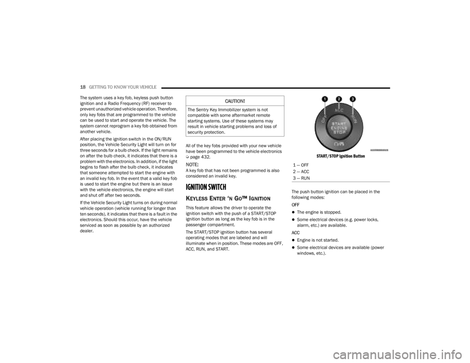
The START/STOP ignition button has several
operating modes that are labeled and will
illuminate when in position. These modes are OFF,
ACC, RUN, and START.
START/STOP Ignition Button
The push button ignition can be placed in the
following modes:
OFF The engine is stopped.
Some electrical devices (e.g. power locks,
alarm, etc.) are available.
ACC
Engine is not started.
Some electrical devices are available (power
windows, etc.).
CAUTION!
The Sentry Key Immobilizer system is not
compatible with some aftermarket remote
starting systems. Use of these systems may
result in vehicle starting problems and loss of
security protection.
1 — OFF
2 — ACC
3 — RUN
23_JT_OM_EN_USC_t.book Page 18
Page 21 of 448
GETTING TO KNOW YOUR VEHICLE19
RUN
Driving position.
All electrical devices are available.
START
The engine will start.
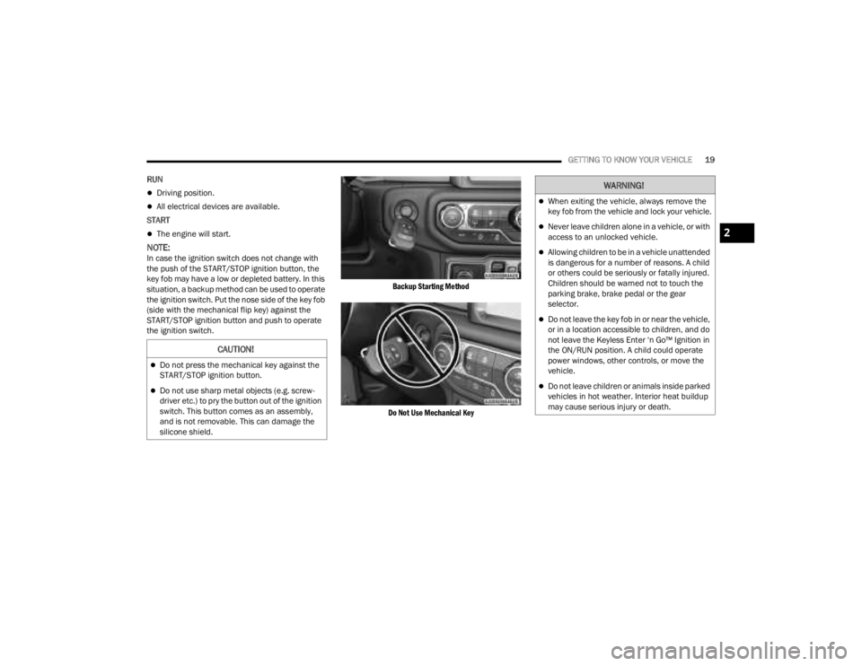
NOTE:In case the ignition switch does not change with
the push of the START/STOP ignition button, the
key fob may have a low or depleted battery. In this
situation, a backup method can be used to operate
the ignition switch. Put the nose side of the key fob
(side with the mechanical flip key) against the
START/STOP ignition button and push to operate
the ignition switch.
Backup Starting Method
Do Not Use Mechanical Key
CAUTION!
Do not press the mechanical key against the
START/STOP ignition button.
Do not use sharp metal objects (e.g. screw -
driver etc.) to pry the button out of the ignition
switch. This button comes as an assembly,
and is not removable. This can damage the
silicone shield.
WARNING!
When exiting the vehicle, always remove the
key fob from the vehicle and lock your vehicle.
Never leave children alone in a vehicle, or with
access to an unlocked vehicle.
Allowing children to be in a vehicle unattended
is dangerous for a number of reasons. A child
or others could be seriously or fatally injured.
Children should be warned not to touch the
parking brake, brake pedal or the gear
selector.
Do not leave the key fob in or near the vehicle,
or in a location accessible to children, and do
not leave the Keyless Enter ‘n Go™ Ignition in
the ON/RUN position. A child could operate
power windows, other controls, or move the
vehicle.
Do not leave children or animals inside parked
vehicles in hot weather. Interior heat buildup
may cause serious injury or death.
2
23_JT_OM_EN_USC_t.book Page 19
Page 23 of 448
GETTING TO KNOW YOUR VEHICLE21
Vehicle Security system indicator flashing
Ignition in OFF position
Fuel level meets minimum requirement
All removable doors must not be removed
Malfunction Indicator Light not illuminated
TO EXIT REMOTE START MODE
To drive the vehicle after starting the Remote Start
system, either push and release the unlock button
on the key fob to unlock the doors, or unlock the
vehicle using Keyless Enter ‘n Go™ — Passive Entry
via the door handles, and disarm the Vehicle
Security system (if equipped). Then, prior to the
end of the 15 minute cycle, push and release the
START/STOP ignition button.
The Remote Start system will turn the engine off if
the Remote Start button on the key fob is pushed
again, or if the engine is allowed to run for the
entire 15 minute cycle. Once the ignition is placed
in the ON/RUN position, the climate controls will
resume previously set operations (temperature,
blower control, etc.).
NOTE:
To avoid unintentional shutdowns, the system
will disable for two seconds after receiving a
valid Remote Start request.
For vehicles equipped with the Keyless
Enter ‘n Go™ — Passive Entry feature, the message “Remote Start Active — Push Start
Button” will display in the instrument cluster
display until you push the START/STOP ignition
button.
REMOTE START FRONT DEFROST
A
CTIVATION — IF EQUIPPED
When Remote Start is active, and the outside
ambient temperature is 40°F (4.5°C) or below, the
system will automatically activate front defrost for
15 minutes or less. The time is dependent on the
ambient temperature. Once the timer expires, the
system will automatically adjust the settings
depending on ambient conditions. See “Remote
Start Comfort Systems — If Equipped” in the next
section for detailed operation.
REMOTE START COMFORT SYSTEMS —
I
F EQUIPPED
When Remote Start is activated, the front and rear
defrost will automatically turn on in cold weather.
The heated steering wheel and driver heated seat
feature will also turn on if programmed in the
Comfort menu screen within Uconnect Settings
Ú page 215.
Automatic Temperature Control (ATC) —
If Equipped
The climate controls automatically adjust to an
optimal temperature and mode, dependent upon
the outside ambient temperature. When the
ignition is placed in the ON/RUN position, the
climate controls will resume their previous
settings.
Manual Temperature Control (MTC) — If Equipped
In ambient temperatures of 40°F (4.5°C) or
below, the climate settings will default to
maximum heat, with fresh air entering the
cabin. If the front defrost timer expires, the
vehicle will enter Mix Mode.
In ambient temperatures from 40°F (4.5°C) to
78°F (26°C), the climate settings will be based
on the last settings selected by the driver.
In ambient temperatures of 78°F (26°C) or
above, the climate settings will default to MAX
A/C, Bi-Level mode, and Recirculation on.
WARNING!
Do not start or run an engine in a closed
garage or confined area. Exhaust gas contains
carbon monoxide (CO) which is odorless and
colorless. Carbon monoxide is poisonous and
can cause serious injury or death when
inhaled.
Keep key fobs away from children. Operation
of the Remote Start system, windows, door
locks or other controls could cause serious
injury or death.
2
23_JT_OM_EN_USC_t.book Page 21
Page 51 of 448
GETTING TO KNOW YOUR VEHICLE49
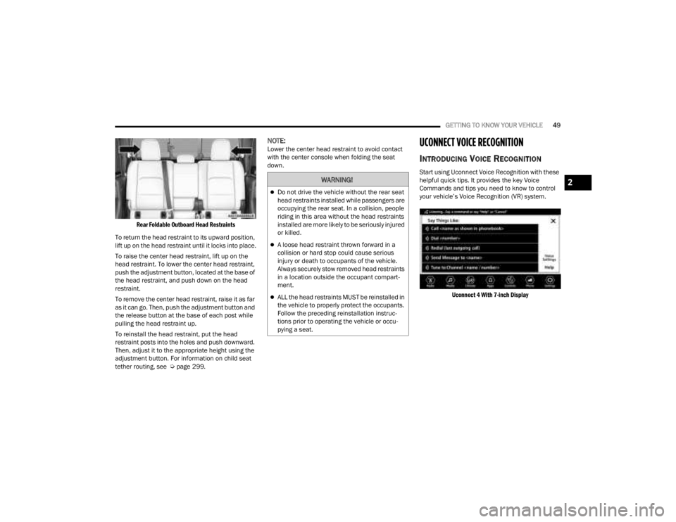
Rear Foldable Outboard Head Restraints
To return the head restraint to its upward position,
lift up on the head restraint until it locks into place.
To raise the center head restraint, lift up on the
head restraint. To lower the center head restraint,
push the adjustment button, located at the base of
the head restraint, and push down on the head
restraint.
To remove the center head restraint, raise it as far
as it can go. Then, push the adjustment button and
the release button at the base of each post while
pulling the head restraint up.
To reinstall the head restraint, put the head
restraint posts into the holes and push downward.
Then, adjust it to the appropriate height using the
adjustment button. For information on child seat
tether routing, see Ú page 299.
NOTE:Lower the center head restraint to avoid contact
with the center console when folding the seat
down.UCONNECT VOICE RECOGNITION
INTRODUCING VOICE RECOGNITION
Start using Uconnect Voice Recognition with these
helpful quick tips. It provides the key Voice
Commands and tips you need to know to control
your vehicle’s Voice Recognition (VR) system.
Uconnect 4 With 7-inch Display
WARNING!
Do not drive the vehicle without the rear seat
head restraints installed while passengers are
occupying the rear seat. In a collision, people
riding in this area without the head restraints
installed are more likely to be seriously injured
or killed.
A loose head restraint thrown forward in a
collision or hard stop could cause serious
injury or death to occupants of the vehicle.
Always securely stow removed head restraints
in a location outside the occupant compart -
ment.
ALL the head restraints MUST be reinstalled in
the vehicle to properly protect the occupants.
Follow the preceding reinstallation instruc -
tions prior to operating the vehicle or occu -
pying a seat.
2
23_JT_OM_EN_USC_t.book Page 49
Page 52 of 448
50GETTING TO KNOW YOUR VEHICLE
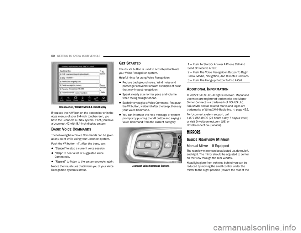
Uconnect 4C/4C NAV with 8.4-inch Display
If you see the NAV icon on the bottom bar or in the
Apps menus of your 8.4-inch touchscreen, you
have the Uconnect 4C NAV system. If not, you have
a Uconnect 4C with 8.4-inch display system.
BASIC VOICE COMMANDS
The following basic Voice Commands can be given
at any point while using your Uconnect system.
Push the VR button . After the beep, say:
“ Cancel ” to stop a current voice session.
“Help ” to hear a list of suggested Voice
Commands.
“ Repeat ” to listen to the system prompts again.
Notice the visual cues that inform you of your Voice
Recognition system’s status.
GET STARTED
The VR button is used to activate/deactivate
your Voice Recognition system.
Helpful hints for using Voice Recognition:
Reduce background noise. Wind noise and
passenger conversations are examples of noise
that may impact recognition.
Speak clearly at a normal pace and volume
while facing straight ahead.
Each time you give a Voice Command, first push
the VR button, wait until after the beep, then say
your Voice Command.
You can interrupt the help message or system
prompts by pushing the VR button and saying a
Voice Command from the current category.
Uconnect Voice Command Buttons
ADDITIONAL INFORMATION
© 2022 FCA US LLC. All rights reserved. Mopar and
Uconnect are registered trademarks and Mopar
Owner Connect is a trademark of FCA US LLC.
SiriusXM® and all related marks and logos are
trademarks of SiriusXM® Radio Inc. Ú page 432.
For Uconnect system support, call
1-877-855-8400 (24 hours a day 7 days a week)
or visit DriveUconnect.com (US) or
DriveUconnect.ca (Canada).
MIRRORS
INSIDE REARVIEW MIRROR
Manual Mirror — If Equipped
The rearview mirror can be adjusted up, down, left,
and right. The mirror should be adjusted to center
on the view through the rear window.
Headlight glare from vehicles behind you can be
reduced by moving the small control under the
mirror to the night position (toward the rear of the
1 — Push To Start Or Answer A Phone Call And
Send Or Receive A Text
2 — Push The Voice Recognition Button To Begin
Radio, Media, Navigation, And Climate Functions
3 — Push The Hang-up Button To End A Call
23_JT_OM_EN_USC_t.book Page 50