stop start JEEP GLADIATOR 2023 User Guide
[x] Cancel search | Manufacturer: JEEP, Model Year: 2023, Model line: GLADIATOR, Model: JEEP GLADIATOR 2023Pages: 448, PDF Size: 17.37 MB
Page 63 of 448
GETTING TO KNOW YOUR VEHICLE61
Rotate the end of the lever upward to the first
detent past the intermittent settings for low-speed
wiper operation. Rotate the end of the lever
upward to the second detent past the intermittent
settings for high-speed wiper operation.
Intermittent Wipers
Use the intermittent wiper when weather
conditions make a single wiping cycle, with a
variable pause between cycles, desirable. Rotate
the end of the lever to the first detent position for
one of four intermittent settings. The delay cycle
can be set anywhere between 1 to 18 seconds.
NOTE:The wiper delay times depend on vehicle speed. If
the vehicle is moving less than 10 mph (16 km/h),
delay times will be doubled. Windshield Washers
To use the washer, pull the lever toward you and
hold until desired spray is reached. If the lever is
pulled while in the delay range, the wiper will start
and continue to operate for two or three wipe
cycles after the lever is released. Then, the
intermittent interval previously selected will
resume.
If the lever is pulled while in the off position, the
wipers will operate for two or three wipe cycles.
Then, the wipers will turn off.
NOTE:As a protective measure, the washer will stop if the
switch is held for more than 20 seconds. Once the
switch is released the washer will resume normal
operation.
Mist
Push upward on the wiper lever to activate a single
wipe to clear off-road mist or spray from a passing
vehicle. As long as the lever is held up, the wipers
will continue to operate.
NOTE:The mist feature does not activate the washer
pump; therefore, no washer fluid will be sprayed on
the windshield. The washer function must be used
in order to spray the windshield with washer fluid.
For information on wiper care and replacement,
see Ú
page 374.
CLIMATE CONTROLS
The Climate Control system allows you to regulate
the temperature, air flow, and direction of air
circulating throughout the vehicle. The controls are
located on the touchscreen and on the instrument
panel below the radio.
CAUTION!
In cold weather, always turn off the wiper switch
and allow the wipers to return to the park
position before turning off the engine. If the
wiper switch is left on and the wipers freeze to
the windshield, damage to the wiper motor may
occur when the vehicle is restarted.
WARNING!
Sudden loss of visibility through the windshield
could lead to a collision. You might not see other
vehicles or other obstacles. To avoid sudden
icing of the windshield during freezing weather,
warm the windshield with the defroster before
and during windshield washer use.
2
23_JT_OM_EN_USC_t.book Page 61
Page 70 of 448
68GETTING TO KNOW YOUR VEHICLE
Window Fogging
Vehicle windows tend to fog on the inside in mild,
rainy, and/or humid weather. To clear the
windows, select Defrost or Mix mode and increase
the front blower speed. Do not use the
Recirculation mode without A/C for long periods,
as fogging may occur.
Outside Air Intake
Make sure the air intake, located directly in front of
the windshield, is free of obstructions, such as
leaves. Leaves collected in the air intake may
reduce airflow, and if they enter the air distribution
box, they could plug the water drains. In Winter
months, make sure the air intake is clear of ice,
slush, and snow.
Cabin Air Filter
The Climate Control system filters out dust and
pollen from the air. Contact an authorized dealer to
service your cabin air filter, and to have it replaced
when needed.
Stop/Start System — If Equipped
While in an Autostop, the Climate Control system
may automatically adjust airflow to maintain cabin
comfort. Customer settings will be maintained
upon return to an engine running condition.
Operating Tips ChartINTERIOR STORAGE AND EQUIPMENT
STORAGE
Glove Compartment
The glove compartment is located on the
passenger side of the instrument panel.
To open the glove compartment, pull the release
handle.
Glove Compartment Release Handle
WEATHER CONTROL SETTINGS
Hot Weather And
Vehicle Interior Is Very
Hot Set the mode control to
(Panel Mode),
(MAX A/C) on, and
blower on high. Roll
down the windows for a
minute to flush out the
hot air. Adjust the
controls as needed to
achieve comfort.
Warm Weather Turn (A/C) on and
set the mode control to
(Panel Mode).
Cool Sunny Operate in (Bi-Level
Mode).
Cool & Humid
Conditions Set the mode control to
(Mix Mode) and
turn on (A/C) to
keep windows clear.
Cold Weather Set the mode control to
(Floor Mode). If
windshield fogging
starts to occur, move
the control to (Mix
Mode).
WARNING!
Do not operate this vehicle with the glove
compartment in the open position. Driving with
the glove compartment open may result in injury
in a collision.
23_JT_OM_EN_USC_t.book Page 68
Page 125 of 448
GETTING TO KNOW YOUR INSTRUMENT PANEL123
and release the OK button. To reset the oil change
indicator system (after performing the scheduled
maintenance), refer to the following procedure.
Oil Life Reset
1. Without pushing the brake pedal, place the ignition in the ON/RUN mode (do not start the
engine).
2. Navigate to "Oil Life" submenu in "Vehicle Info" in the instrument cluster display.
3. Push and hold the OK button until the gauge
resets to 100%.
Secondary Method For Oil Change Reset
Procedure
1. Without pushing the brake pedal, place the ignition in the ON/RUN position (do not start
the engine).
2. Fully press the accelerator pedal, slowly, three times within ten seconds.
3. Without pushing the brake pedal, place the ignition in the OFF position.
NOTE:If the indicator message illuminates when you start
the vehicle, the oil change indicator system did not
reset. If necessary, repeat this procedure.
OFF ROAD+ DISPLAY — IF EQUIPPED
When the Off Road+ button is pushed in the switch
bank, the Instrument Cluster Display will begin to
show messages related to the feature. Depending
on the Four Wheel Drive mode in use, the
messages will differ, and after five seconds, all
messages will clear from the display. The
messages are as follows:
2H: Off Road+ Unavailable, Shift to 4WD
4H: 4WD High Off Road+ Active
4L: 4WD Low Off Road+ Active
Adaptive Cruise Control (ACC) and Cruise Control
are not available when using Off Road+. If either
option is selected, a dedicated message will
display indicating that the features are not usable
concurrently. Messages are as follows:
4H: Cruise Control — Cruise Control Unavailable
in Off Road+
4H: Adaptive Cruise Control — Adaptive Cruise
Control (ACC) Unavailable in Off Road+
4L: Cruise Control — Cruise Control Unavailable
in 4WD Low
4L: Adaptive Cruise Control — Adaptive Cruise
Control (ACC) Unavailable in 4WD Low
NOTE:The behavior of Electronic Stability Control while in
Off Road+ varies depending on the 4WD status. If
the vehicle is in 4WD High, Traction Control is auto -
matically turned off. Also, holding the ESC OFF
button for five seconds will turn off ESC. In 4WD
Low, Electronic Stability Control automatically
shuts off regardless of the Off Road Status.
INSTRUMENT CLUSTER DISPLAY
S
ELECTABLE ITEMS
The instrument cluster display can be used to view
the following main menu items:
NOTE:Depending on the vehicles options, feature
settings may vary.
Speedometer Driver Assist —
If EquippedMessages
Vehicle Info Trip Info Screen Setup
Fuel Economy Stop/Start Audio
Off Road —
If Equipped
3
23_JT_OM_EN_USC_t.book Page 123
Page 127 of 448
GETTING TO KNOW YOUR INSTRUMENT PANEL125
ACC SET
When ACC is set, the set speed will display in the
instrument cluster.
The ACC screen may display once again if any ACC
activity occurs, which may include any of the
following:
System Cancel
Driver Override
System Off
ACC Proximity Warning
ACC Unavailable Warning
NOTE:The instrument cluster display will return to the last
display selected after five seconds of no ACC
display activity Ú page 175.
Fuel Economy
Push and release the up or down arrow
button until the Fuel Economy icon is highlighted in
the instrument cluster display. Push and hold the
OK button to reset average fuel economy feature.
Toggle left or right to select a display with or
without Current Fuel Economy Information.
Range – The display shows the estimated
distance (mi or km) that can be traveled with the
fuel remaining in the tank. When the Range
value is less than 10 miles (16 km), the Range
display will change to a “LOW” message. Adding a significant amount of fuel to the vehicle will
turn off the “LOW” message and a new Range
value will display. Range cannot be reset
through the
OK button.
NOTE:Significant changes in driving style or vehicle
loading will greatly affect the actual drivable
distance of the vehicle, regardless of the Range
displayed value.
Average – The display shows the average fuel
economy (MPG, L/100km, or km/L) since the
last reset.
Current – The display shows the current fuel
economy (MPG, L/100km, or km/L) while
driving.
Trip
Push and release the up or down arrow
button until the Trip icon/title is highlighted in the
instrument cluster display, then push and release
the left or right arrow button to select Trip A
or Trip B.
The Trip A and Trip B information will display the
following:
Distance
Average Fuel Economy
Elapsed Time
Hold the OK button to reset all the information.
Stop/Start — If Equipped
Push and release the up or down arrow
button until the Stop/Start icon/title is highlighted
in the instrument cluster display. The screen will
display the Stop/Start status.
Audio
Push and release the up or down arrow
button until the Stop/Start icon/title is highlighted
in the instrument cluster display. The screen will
display the Stop/Start status.
Phone Call Status
When a call is incoming, a Phone Call Status
pop-up will display on the screen. The pop-up will
remain until the phone is answered or ignored.
NOTE:The call status will temporarily replace the
previous media source information displayed on
the screen. When the pop-up is no longer
displayed, the display will return to the last used
screen.
Stored Messages
Push and release the up or down arrow
button until the Messages Menu item is
highlighted. This feature shows the number of
stored warning messages. Pushing the right
arrow button will allow you to see what the stored
messages are.
3
23_JT_OM_EN_USC_t.book Page 125
Page 128 of 448
126GETTING TO KNOW YOUR INSTRUMENT PANEL
When no messages are present, main menu icon
will be a closed envelope, and “No Stored
Messages” will display.
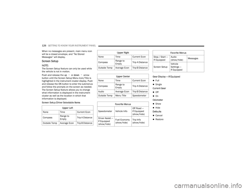
Screen Setup
NOTE:The Screen Setup feature can only be used while
the vehicle is not in motion.
Push and release the up or down arrow
button until the Screen Setup Menu Icon/Title is
highlighted in the instrument cluster display. Push
and release the OK button to enter the submenus
and follow the prompts on the screen as needed.
The Screen Setup feature allows you to change
what information is displayed in the instrument
cluster as well as the location in which that
information is displayed.
Screen Setup Driver Selectable Items Gear Display — If Equipped
Full
Single
Current Gear
Off
On
Odometer
Show
Hide
Defaults
Cancel
Restore
Upper Left
None Time Current Econ
Compass Range to
EmptyTrip A Distance
Outside Temp Average Econ Trip B Distance
Upper Right
None Time Current Econ
Compass Range to
EmptyTrip A Distance
Outside Temp Average Econ Trip B Distance
Upper Center
None Time Current Econ
Compass Range to
EmptyTrip A Distance
Audio Average Econ Trip B Distance
Outside Temp Menu Title Speedometer
Favorite Menus
Speedometer Vehicle Info Off Road —
If Equipped
(show/hide)
Driver Assist —
If Equipped
(show/hide) Fuel Economy
(show/hide)
Trip Info
(show/hide)
Stop / Start —
If EquippedAudio
(show/hide)
Messages
Screen Setup Vehicle
Settings —
If Equipped
Favorite Menus
23_JT_OM_EN_USC_t.book Page 126
Page 129 of 448
GETTING TO KNOW YOUR INSTRUMENT PANEL127
BATTERY SAVER ON, BATTERY SAVER
M
ODE MESSAGE, AND ELECTRICAL
L
OAD REDUCTION ACTIONS
(I
F EQUIPPED)
This vehicle is equipped with an Intelligent Battery
Sensor (IBS) to perform additional monitoring of
the electrical system and status of the vehicle
battery.
In cases when the IBS detects charging system
failure, or the vehicle battery conditions are
deteriorating, electrical load reduction actions will
take place to extend the driving time and distance
of the vehicle. This is done by reducing power to or
turning off non-essential electrical loads.
Load reduction is only active when the engine is
running. It will display a message if there is a risk
of battery depletion to the point where the vehicle
may stall due to lack of electrical supply, or will not
restart after the current drive cycle.
When load reduction is activated, the message
“Battery Saver On Some Systems May Have
Reduced Power” will appear in the instrument
cluster. These messages indicate the vehicle battery has a
low state of charge and continues to lose electrical
charge at a rate that the charging system cannot
sustain.
NOTE:
The charging system is independent from load
reduction. The charging system performs a diag
-
nostic on the charging system continuously.
If the Battery Charge Warning Light is on it may
indicate a problem with the charging system
Ú page 133.
The electrical loads that may be switched off (if
equipped), and vehicle functions which can be
affected by load reduction:
Heated Seat/Vented Seats/Heated Wheel
Rear Defroster And Heated Mirrors
HVAC System
115 Volt AC Power Inverter System
Audio and Telematics System
Loss of battery charge may indicate one or more of
the following conditions:
The charging system cannot deliver enough
electrical power to the vehicle system because
the electrical loads are larger than the capability
of the charging system. The charging system is
still functioning properly.
Turning on all possible vehicle electrical loads
(e.g. HVAC to max settings, exterior and interior
lights, overloaded power outlets +12 Volt,
115 Volt AC, USB ports) during certain driving
conditions (city driving, towing, frequent stop -
ping).
Installing options like additional lights, upfitter
electrical accessories, audio systems, alarms
and similar devices.
Unusual driving cycles (short trips separated by
long parking periods).
The vehicle was parked for an extended period
of time (weeks, months).
The battery was recently replaced and was not
charged completely.
The battery was discharged by an electrical load
left on when the vehicle was parked.
The battery was used for an extended period
with the engine not running to supply radio,
lights, chargers, +12 Volt portable appliances
like vacuum cleaners, game consoles and
similar devices.
3
23_JT_OM_EN_USC_t.book Page 127
Page 132 of 448
130GETTING TO KNOW YOUR INSTRUMENT PANEL
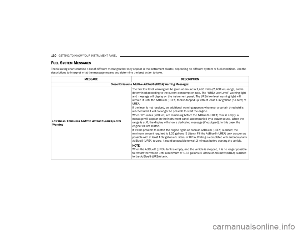
FUEL SYSTEM MESSAGES
The following chart contains a list of different messages that may appear in the instrument cluster, depending on different system or fuel conditions. Use the
descriptions to interpret what the message means and determine the best action to take.
MESSAGE DESCRIPTION
Diesel Emissions Additive AdBlue® (UREA) Warning Messages:
Low Diesel Emissions Additive AdBlue® (UREA) Level
Warning The first low level warning will be given at around a 1,490 miles (2,400 km) range, and is
determined according to the current consumption rate. The “UREA Low Level” warning light
and message will display on the instrument panel. The UREA low level warning light will
remain lit until the AdBlue® (UREA) tank is topped up with at least 1.32 gallons (5 Liters) of
UREA.
If the level is not resolved, an additional warning appears whenever a certain threshold is
reached until it will no longer be possible to start the engine.
When 125 miles (200 km) are remaining before the AdBlue® (UREA) tank is empty, a
message will appear on the instrument panel, accompanied by a buzzer sound. When the
range is at 0, the display will show a dedicated message (if equipped). In this case, the
engine will not restart.
It will be possible to restart the engine again as soon as AdBlue® (UREA) is added; the
minimum amount required is 1.32 gallons (5 Liters). Fill the AdBlue® (UREA) tank as soon as
possible with at least 1.32 gallons (5 Liters) of UREA. If filling is completed with autonomy tank
AdBlue® (UREA) to zero, it could be possible to wait 2 minutes before starting the vehicle.
NOTE:When the AdBlue® (UREA) tank is empty, and the vehicle is stopped, it is no longer possible
to restart the vehicle until a minimum of 1.32 gallons (5 Liters) of AdBlue® (UREA) is added
to the AdBlue® (UREA) tank.
23_JT_OM_EN_USC_t.book Page 130
Page 134 of 448
132GETTING TO KNOW YOUR INSTRUMENT PANEL
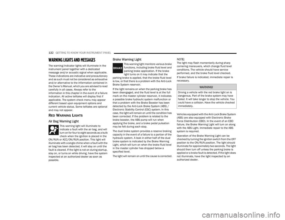
WARNING LIGHTS AND MESSAGES
The warning/indicator lights will illuminate in the
instrument panel together with a dedicated
message and/or acoustic signal when applicable.
These indications are indicative and precautionary
and as such must not be considered as exhaustive
and/or alternative to the information contained in
the Owner’s Manual, which you are advised to read
carefully in all cases. Always refer to the
information in this chapter in the event of a failure
indication. All active telltales will display first if
applicable. The system check menu may appear
different based upon equipment options and
current vehicle status. Some telltales are optional
and may not appear.
RED WARNING LIGHTS
Air Bag Warning Light
This warning light will illuminate to
indicate a fault with the air bag, and will
turn on for four to eight seconds as a bulb
check when the ignition is placed in the
ON/RUN or ACC/ON/RUN position. This light will
illuminate with a single chime when a fault with the
air bag has been detected, it will stay on until the
fault is cleared. If the light is not on during startup,
stay on, or turns on while driving, have the system
inspected at an authorized dealer as soon as
possible.
Brake Warning Light
This warning light monitors various brake
functions, including brake fluid level and
parking brake application. If the brake
light turns on it may indicate that the
parking brake is applied, that the brake fluid level
is low, or that there is a problem with the Anti-Lock
Brake System reservoir.
If the light remains on when the parking brake has
been disengaged, and the fluid level is at the full
mark on the master cylinder reservoir, it indicates
a possible brake hydraulic system malfunction or
that a problem with the Brake Booster has been
detected by the Anti-Lock Brake System (ABS) /
Electronic Stability Control (ESC) system. In this
case, the light will remain on until the condition has
been corrected. If the problem is related to the
brake booster, the ABS pump will run when
applying the brake, and a brake pedal pulsation
may be felt during each stop.
The dual brake system provides a reserve braking
capacity in the event of a failure to a portion of the
hydraulic system. A leak in either half of the dual
brake system is indicated by the Brake Warning
Light, which will turn on when the brake fluid level
in the master cylinder has dropped below a
specified level.
The light will remain on until the cause is corrected.
NOTE:The light may flash momentarily during sharp
cornering maneuvers, which change fluid level
conditions. The vehicle should have service
performed, and the brake fluid level checked.
If brake failure is indicated, immediate repair is
necessary.
Vehicles equipped with the Anti-Lock Brake System
(ABS) are also equipped with Electronic Brake
Force Distribution (EBD). In the event of an EBD
failure, the Brake Warning Light will turn on along
with the ABS Light. Immediate repair to the ABS
system is required.
Operation of the Brake Warning Light can be
checked by turning the ignition switch from the OFF
position to the ON/RUN position. The light should
illuminate for approximately two seconds. The light
should then turn off unless the parking brake is
applied or a brake fault is detected. If the light does
not illuminate, have the light inspected by an
authorized dealer.
WARNING!
Driving a vehicle with the red brake light on is
dangerous. Part of the brake system may have
failed. It will take longer to stop the vehicle. You
could have a collision. Have the vehicle checked
immediately.
23_JT_OM_EN_USC_t.book Page 132
Page 135 of 448
GETTING TO KNOW YOUR INSTRUMENT PANEL133
The light also will turn on when the parking brake
is applied with the ignition switch in the ON/RUN
position.
NOTE:This light shows only that the parking brake is
applied. It does not show the degree of brake appli -
cation.
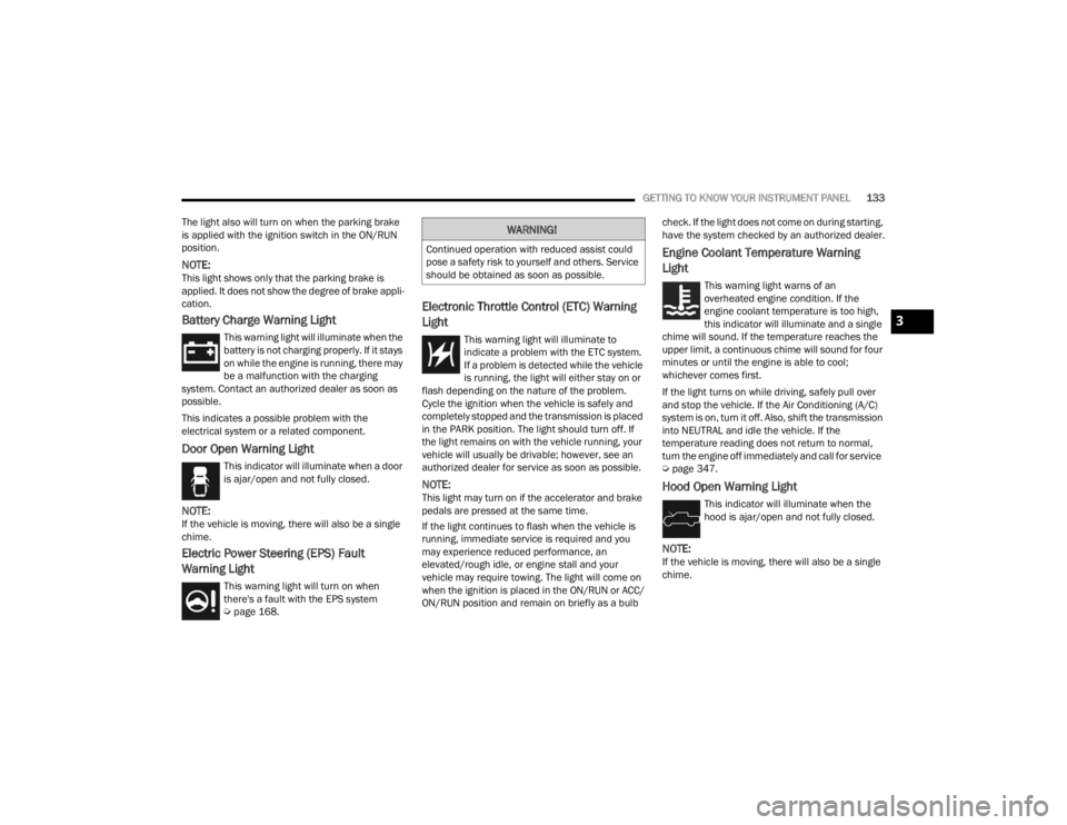
Battery Charge Warning Light
This warning light will illuminate when the
battery is not charging properly. If it stays
on while the engine is running, there may
be a malfunction with the charging
system. Contact an authorized dealer as soon as
possible.
This indicates a possible problem with the
electrical system or a related component.
Door Open Warning Light
This indicator will illuminate when a door
is ajar/open and not fully closed.
NOTE:If the vehicle is moving, there will also be a single
chime.
Electric Power Steering (EPS) Fault
Warning Light
This warning light will turn on when
there's a fault with the EPS system
Ú page 168.
Electronic Throttle Control (ETC) Warning
Light
This warning light will illuminate to
indicate a problem with the ETC system.
If a problem is detected while the vehicle
is running, the light will either stay on or
flash depending on the nature of the problem.
Cycle the ignition when the vehicle is safely and
completely stopped and the transmission is placed
in the PARK position. The light should turn off. If
the light remains on with the vehicle running, your
vehicle will usually be drivable; however, see an
authorized dealer for service as soon as possible.
NOTE:This light may turn on if the accelerator and brake
pedals are pressed at the same time.
If the light continues to flash when the vehicle is
running, immediate service is required and you
may experience reduced performance, an
elevated/rough idle, or engine stall and your
vehicle may require towing. The light will come on
when the ignition is placed in the ON/RUN or ACC/
ON/RUN position and remain on briefly as a bulb check. If the light does not come on during starting,
have the system checked by an authorized dealer.
Engine Coolant Temperature Warning
Light
This warning light warns of an
overheated engine condition. If the
engine coolant temperature is too high,
this indicator will illuminate and a single
chime will sound. If the temperature reaches the
upper limit, a continuous chime will sound for four
minutes or until the engine is able to cool;
whichever comes first.
If the light turns on while driving, safely pull over
and stop the vehicle. If the Air Conditioning (A/C)
system is on, turn it off. Also, shift the transmission
into NEUTRAL and idle the vehicle. If the
temperature reading does not return to normal,
turn the engine off immediately and call for service
Ú page 347.
Hood Open Warning Light
This indicator will illuminate when the
hood is ajar/open and not fully closed.
NOTE:If the vehicle is moving, there will also be a single
chime.
WARNING!
Continued operation with reduced assist could
pose a safety risk to yourself and others. Service
should be obtained as soon as possible.
3
23_JT_OM_EN_USC_t.book Page 133
Page 136 of 448
134GETTING TO KNOW YOUR INSTRUMENT PANEL
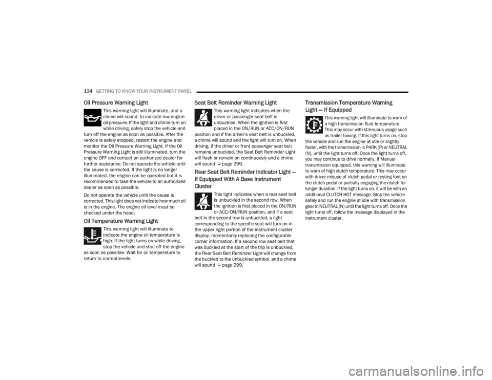
Oil Pressure Warning Light
This warning light will illuminate, and a
chime will sound, to indicate low engine
oil pressure. If the light and chime turn on
while driving, safely stop the vehicle and
turn off the engine as soon as possible. After the
vehicle is safely stopped, restart the engine and
monitor the Oil Pressure Warning Light. If the Oil
Pressure Warning Light is still illuminated, turn the
engine OFF and contact an authorized dealer for
further assistance. Do not operate the vehicle until
the cause is corrected. If the light is no longer
illuminated, the engine can be operated but it is
recommended to take the vehicle to an authorized
dealer as soon as possible.
Do not operate the vehicle until the cause is
corrected. This light does not indicate how much oil
is in the engine. The engine oil level must be
checked under the hood.
Oil Temperature Warning Light
This warning light will illuminate to
indicate the engine oil temperature is
high. If the light turns on while driving,
stop the vehicle and shut off the engine
as soon as possible. Wait for oil temperature to
return to normal levels.
Seat Belt Reminder Warning Light
This warning light indicates when the
driver or passenger seat belt is
unbuckled. When the ignition is first
placed in the ON/RUN or ACC/ON/RUN
position and if the driver’s seat belt is unbuckled,
a chime will sound and the light will turn on. When
driving, if the driver or front passenger seat belt
remains unbuckled, the Seat Belt Reminder Light
will flash or remain on continuously and a chime
will sound Ú page 299.
Rear Seat Belt Reminder Indicator Light —
If Equipped With A Base Instrument
Cluster
This light indicates when a rear seat belt
is unbuckled in the second row. When
the ignition is first placed in the ON/RUN
or ACC/ON/RUN position, and if a seat
belt in the second row is unbuckled, a light
corresponding to the specific seat will turn on in
the upper right portion of the instrument cluster
display, momentarily replacing the configurable
corner information. If a second row seat belt that
was buckled at the start of the trip is unbuckled,
the Rear Seat Belt Reminder Light will change from
the buckled to the unbuckled symbol, and a chime
will sound Ú page 299.
Transmission Temperature Warning
Light — If Equipped
This warning light will illuminate to warn of
a high transmission fluid temperature.
This may occur with strenuous usage such
as trailer towing. If this light turns on, stop
the vehicle and run the engine at idle or slightly
faster, with the transmission in PARK (P) or NEUTRAL
(N), until the light turns off. Once the light turns off,
you may continue to drive normally. If Manual
transmission equipped, this warning will illuminate
to warn of high clutch temperature. This may occur
with driver misuse of clutch pedal or resting foot on
the clutch pedal or partially engaging the clutch for
longer duration. If the light turns on, it will be with an
additional CLUTCH HOT message. Stop the vehicle
safely and run the engine at idle with transmission
gear in NEUTRAL (N) until the light turns off. Once the
light turns off, follow the message displayed in the
instrument cluster.
23_JT_OM_EN_USC_t.book Page 134