tow JEEP GLADIATOR 2023 User Guide
[x] Cancel search | Manufacturer: JEEP, Model Year: 2023, Model line: GLADIATOR, Model: JEEP GLADIATOR 2023Pages: 448, PDF Size: 17.37 MB
Page 48 of 448
46GETTING TO KNOW YOUR VEHICLE
NOTE:
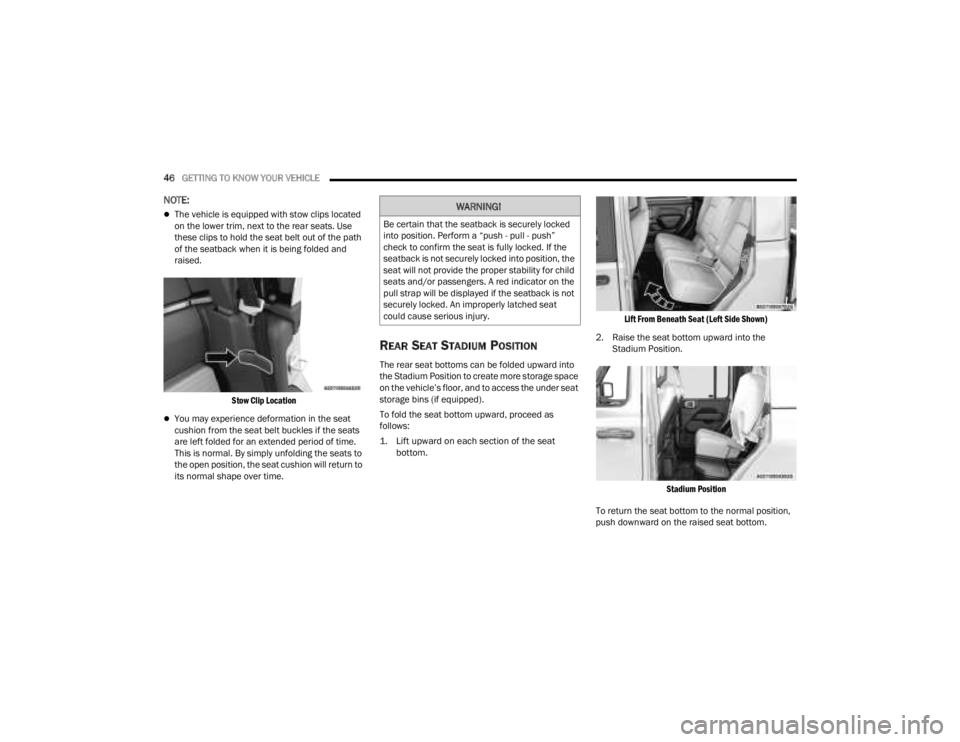
The vehicle is equipped with stow clips located
on the lower trim, next to the rear seats. Use
these clips to hold the seat belt out of the path
of the seatback when it is being folded and
raised.
Stow Clip Location
You may experience deformation in the seat
cushion from the seat belt buckles if the seats
are left folded for an extended period of time.
This is normal. By simply unfolding the seats to
the open position, the seat cushion will return to
its normal shape over time.
REAR SEAT STADIUM POSITION
The rear seat bottoms can be folded upward into
the Stadium Position to create more storage space
on the vehicle’s floor, and to access the under seat
storage bins (if equipped).
To fold the seat bottom upward, proceed as
follows:
1. Lift upward on each section of the seat bottom.
Lift From Beneath Seat (Left Side Shown)
2. Raise the seat bottom upward into the Stadium Position.
Stadium Position
To return the seat bottom to the normal position,
push downward on the raised seat bottom.
WARNING!
Be certain that the seatback is securely locked
into position. Perform a “push - pull - push”
check to confirm the seat is fully locked. If the
seatback is not securely locked into position, the
seat will not provide the proper stability for child
seats and/or passengers. A red indicator on the
pull strap will be displayed if the seatback is not
securely locked. An improperly latched seat
could cause serious injury.
23_JT_OM_EN_USC_t.book Page 46
Page 50 of 448
48GETTING TO KNOW YOUR VEHICLE
HEAD RESTRAINTS
Head restraints are designed to reduce the risk of
injury by restricting head movement in the event of
a rear impact. Head restraints should be adjusted
so that the top of the head restraint is located
above the top of your ear.
Front Head Restraints
To raise the head restraint, pull upward on the
head restraint. To lower the head restraint, push
the adjustment button located on the base of the
head restraint, and push downward on the head
restraint. The release button does not need to be
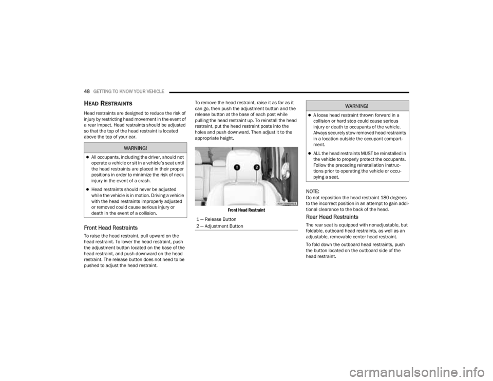
pushed to adjust the head restraint. To remove the head restraint, raise it as far as it
can go, then push the adjustment button and the
release button at the base of each post while
pulling the head restraint up. To reinstall the head
restraint, put the head restraint posts into the
holes and push downward. Then adjust it to the
appropriate height.
Front Head Restraint
NOTE:Do not reposition the head restraint 180 degrees
to the incorrect position in an attempt to gain addi -
tional clearance to the back of the head.
Rear Head Restraints
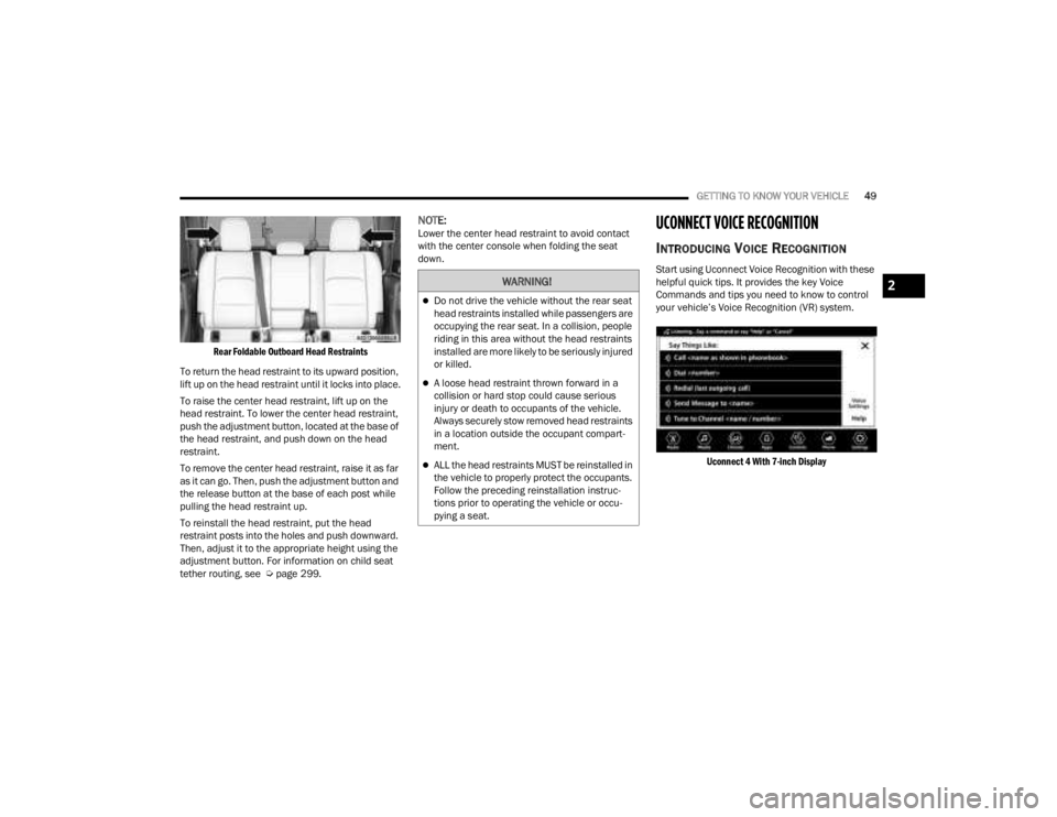
The rear seat is equipped with nonadjustable, but
foldable, outboard head restraints, as well as an
adjustable, removable center head restraint.
To fold down the outboard head restraints, push
the button located on the outboard side of the
head restraint.
WARNING!
All occupants, including the driver, should not
operate a vehicle or sit in a vehicle’s seat until
the head restraints are placed in their proper
positions in order to minimize the risk of neck
injury in the event of a crash.
Head restraints should never be adjusted
while the vehicle is in motion. Driving a vehicle
with the head restraints improperly adjusted
or removed could cause serious injury or
death in the event of a collision.
1 — Release Button
2 — Adjustment Button
WARNING!
A loose head restraint thrown forward in a
collision or hard stop could cause serious
injury or death to occupants of the vehicle.
Always securely stow removed head restraints
in a location outside the occupant compart -
ment.
ALL the head restraints MUST be reinstalled in
the vehicle to properly protect the occupants.
Follow the preceding reinstallation instruc -
tions prior to operating the vehicle or occu -
pying a seat.
23_JT_OM_EN_USC_t.book Page 48
Page 51 of 448
GETTING TO KNOW YOUR VEHICLE49
Rear Foldable Outboard Head Restraints
To return the head restraint to its upward position,
lift up on the head restraint until it locks into place.
To raise the center head restraint, lift up on the
head restraint. To lower the center head restraint,
push the adjustment button, located at the base of
the head restraint, and push down on the head
restraint.
To remove the center head restraint, raise it as far
as it can go. Then, push the adjustment button and
the release button at the base of each post while
pulling the head restraint up.
To reinstall the head restraint, put the head
restraint posts into the holes and push downward.
Then, adjust it to the appropriate height using the
adjustment button. For information on child seat
tether routing, see Ú page 299.
NOTE:Lower the center head restraint to avoid contact
with the center console when folding the seat
down.UCONNECT VOICE RECOGNITION
INTRODUCING VOICE RECOGNITION
Start using Uconnect Voice Recognition with these
helpful quick tips. It provides the key Voice
Commands and tips you need to know to control
your vehicle’s Voice Recognition (VR) system.
Uconnect 4 With 7-inch Display
WARNING!
Do not drive the vehicle without the rear seat
head restraints installed while passengers are
occupying the rear seat. In a collision, people
riding in this area without the head restraints
installed are more likely to be seriously injured
or killed.
A loose head restraint thrown forward in a
collision or hard stop could cause serious
injury or death to occupants of the vehicle.
Always securely stow removed head restraints
in a location outside the occupant compart -
ment.
ALL the head restraints MUST be reinstalled in
the vehicle to properly protect the occupants.
Follow the preceding reinstallation instruc -
tions prior to operating the vehicle or occu -
pying a seat.
2
23_JT_OM_EN_USC_t.book Page 49
Page 52 of 448
50GETTING TO KNOW YOUR VEHICLE
Uconnect 4C/4C NAV with 8.4-inch Display
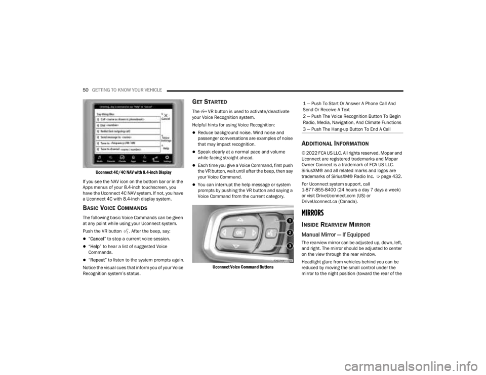
If you see the NAV icon on the bottom bar or in the
Apps menus of your 8.4-inch touchscreen, you
have the Uconnect 4C NAV system. If not, you have
a Uconnect 4C with 8.4-inch display system.
BASIC VOICE COMMANDS
The following basic Voice Commands can be given
at any point while using your Uconnect system.
Push the VR button . After the beep, say:
“ Cancel ” to stop a current voice session.
“Help ” to hear a list of suggested Voice
Commands.
“ Repeat ” to listen to the system prompts again.
Notice the visual cues that inform you of your Voice
Recognition system’s status.
GET STARTED
The VR button is used to activate/deactivate
your Voice Recognition system.
Helpful hints for using Voice Recognition:
Reduce background noise. Wind noise and
passenger conversations are examples of noise
that may impact recognition.
Speak clearly at a normal pace and volume
while facing straight ahead.
Each time you give a Voice Command, first push
the VR button, wait until after the beep, then say
your Voice Command.
You can interrupt the help message or system
prompts by pushing the VR button and saying a
Voice Command from the current category.
Uconnect Voice Command Buttons
ADDITIONAL INFORMATION
© 2022 FCA US LLC. All rights reserved. Mopar and
Uconnect are registered trademarks and Mopar
Owner Connect is a trademark of FCA US LLC.
SiriusXM® and all related marks and logos are
trademarks of SiriusXM® Radio Inc. Ú page 432.
For Uconnect system support, call
1-877-855-8400 (24 hours a day 7 days a week)
or visit DriveUconnect.com (US) or
DriveUconnect.ca (Canada).
MIRRORS
INSIDE REARVIEW MIRROR
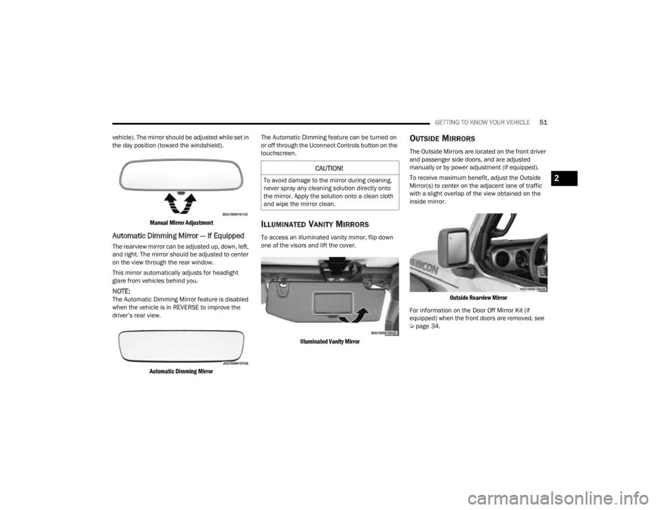
Manual Mirror — If Equipped
The rearview mirror can be adjusted up, down, left,
and right. The mirror should be adjusted to center
on the view through the rear window.
Headlight glare from vehicles behind you can be
reduced by moving the small control under the
mirror to the night position (toward the rear of the
1 — Push To Start Or Answer A Phone Call And
Send Or Receive A Text
2 — Push The Voice Recognition Button To Begin
Radio, Media, Navigation, And Climate Functions
3 — Push The Hang-up Button To End A Call
23_JT_OM_EN_USC_t.book Page 50
Page 53 of 448
GETTING TO KNOW YOUR VEHICLE51
vehicle). The mirror should be adjusted while set in
the day position (toward the windshield).
Manual Mirror Adjustment
Automatic Dimming Mirror — If Equipped
The rearview mirror can be adjusted up, down, left,
and right. The mirror should be adjusted to center
on the view through the rear window.
This mirror automatically adjusts for headlight
glare from vehicles behind you.
NOTE:The Automatic Dimming Mirror feature is disabled
when the vehicle is in REVERSE to improve the
driver’s rear view.
Automatic Dimming Mirror
The Automatic Dimming feature can be turned on
or off through the Uconnect Controls button on the
touchscreen.
ILLUMINATED VANITY MIRRORS
To access an illuminated vanity mirror, flip down
one of the visors and lift the cover.
Illuminated Vanity Mirror
OUTSIDE MIRRORS
The Outside Mirrors are located on the front driver
and passenger side doors, and are adjusted
manually or by power adjustment (if equipped).
To receive maximum benefit, adjust the Outside
Mirror(s) to center on the adjacent lane of traffic
with a slight overlap of the view obtained on the
inside mirror.
Outside Rearview Mirror
For information on the Door Off Mirror Kit (if
equipped) when the front doors are removed, see
Ú page 34.
CAUTION!
To avoid damage to the mirror during cleaning,
never spray any cleaning solution directly onto
the mirror. Apply the solution onto a clean cloth
and wipe the mirror clean.2
23_JT_OM_EN_USC_t.book Page 51
Page 59 of 448
GETTING TO KNOW YOUR VEHICLE57
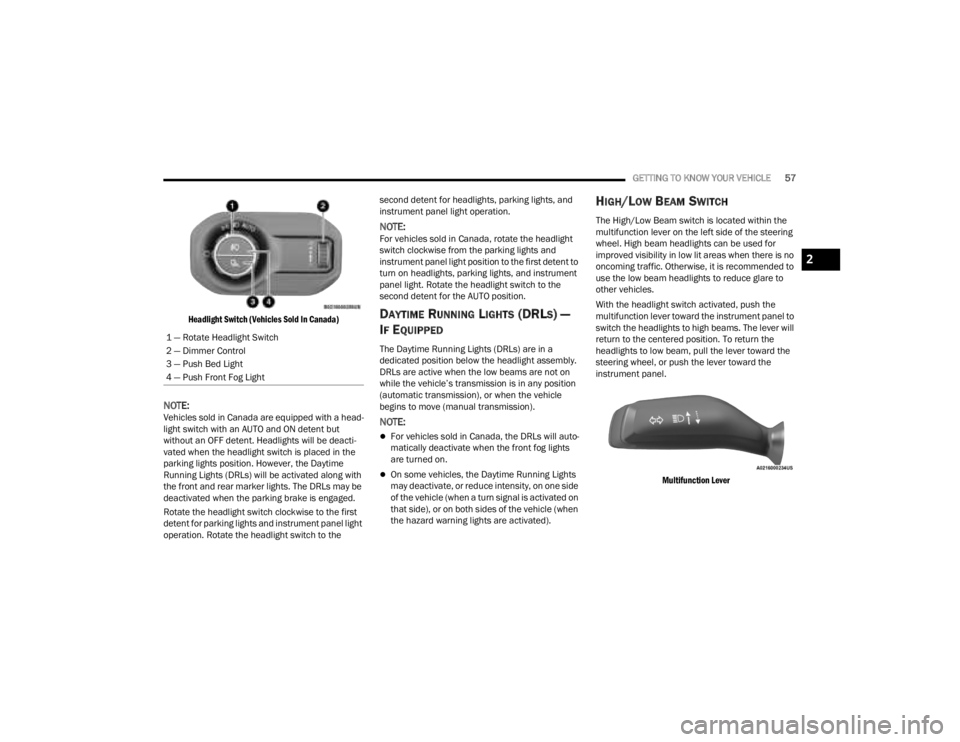
Headlight Switch (Vehicles Sold In Canada)
NOTE:Vehicles sold in Canada are equipped with a head -
light switch with an AUTO and ON detent but
without an OFF detent. Headlights will be deacti -
vated when the headlight switch is placed in the
parking lights position. However, the Daytime
Running Lights (DRLs) will be activated along with
the front and rear marker lights. The DRLs may be
deactivated when the parking brake is engaged.
Rotate the headlight switch clockwise to the first
detent for parking lights and instrument panel light
operation. Rotate the headlight switch to the second detent for headlights, parking lights, and
instrument panel light operation.
NOTE:For vehicles sold in Canada, rotate the headlight
switch clockwise from the parking lights and
instrument panel light position to the first detent to
turn on headlights, parking lights, and instrument
panel light. Rotate the headlight switch to the
second detent for the AUTO position.
DAYTIME RUNNING LIGHTS (DRLS) —
I
F EQUIPPED
The Daytime Running Lights (DRLs) are in a
dedicated position below the headlight assembly.
DRLs are active when the low beams are not on
while the vehicle’s transmission is in any position
(automatic transmission), or when the vehicle
begins to move (manual transmission).
NOTE:
For vehicles sold in Canada, the DRLs will auto -
matically deactivate when the front fog lights
are turned on.
On some vehicles, the Daytime Running Lights
may deactivate, or reduce intensity, on one side
of the vehicle (when a turn signal is activated on
that side), or on both sides of the vehicle (when
the hazard warning lights are activated).
HIGH/LOW BEAM SWITCH
The High/Low Beam switch is located within the
multifunction lever on the left side of the steering
wheel. High beam headlights can be used for
improved visibility in low lit areas when there is no
oncoming traffic. Otherwise, it is recommended to
use the low beam headlights to reduce glare to
other vehicles.
With the headlight switch activated, push the
multifunction lever toward the instrument panel to
switch the headlights to high beams. The lever will
return to the centered position. To return the
headlights to low beam, pull the lever toward the
steering wheel, or push the lever toward the
instrument panel.
Multifunction Lever
1 — Rotate Headlight Switch
2 — Dimmer Control
3 — Push Bed Light
4 — Push Front Fog Light
2
23_JT_OM_EN_USC_t.book Page 57
Page 63 of 448
GETTING TO KNOW YOUR VEHICLE61
Rotate the end of the lever upward to the first
detent past the intermittent settings for low-speed
wiper operation. Rotate the end of the lever
upward to the second detent past the intermittent
settings for high-speed wiper operation.
Intermittent Wipers
Use the intermittent wiper when weather
conditions make a single wiping cycle, with a
variable pause between cycles, desirable. Rotate
the end of the lever to the first detent position for
one of four intermittent settings. The delay cycle
can be set anywhere between 1 to 18 seconds.
NOTE:The wiper delay times depend on vehicle speed. If
the vehicle is moving less than 10 mph (16 km/h),
delay times will be doubled. Windshield Washers
To use the washer, pull the lever toward you and
hold until desired spray is reached. If the lever is
pulled while in the delay range, the wiper will start
and continue to operate for two or three wipe
cycles after the lever is released. Then, the
intermittent interval previously selected will
resume.
If the lever is pulled while in the off position, the
wipers will operate for two or three wipe cycles.
Then, the wipers will turn off.
NOTE:As a protective measure, the washer will stop if the
switch is held for more than 20 seconds. Once the
switch is released the washer will resume normal
operation.
Mist
Push upward on the wiper lever to activate a single
wipe to clear off-road mist or spray from a passing
vehicle. As long as the lever is held up, the wipers
will continue to operate.
NOTE:The mist feature does not activate the washer
pump; therefore, no washer fluid will be sprayed on
the windshield. The washer function must be used
in order to spray the windshield with washer fluid.
For information on wiper care and replacement,
see Ú
page 374.
CLIMATE CONTROLS
The Climate Control system allows you to regulate
the temperature, air flow, and direction of air
circulating throughout the vehicle. The controls are
located on the touchscreen and on the instrument
panel below the radio.
CAUTION!
In cold weather, always turn off the wiper switch
and allow the wipers to return to the park
position before turning off the engine. If the
wiper switch is left on and the wipers freeze to
the windshield, damage to the wiper motor may
occur when the vehicle is restarted.
WARNING!
Sudden loss of visibility through the windshield
could lead to a collision. You might not see other
vehicles or other obstacles. To avoid sudden
icing of the windshield during freezing weather,
warm the windshield with the defroster before
and during windshield washer use.
2
23_JT_OM_EN_USC_t.book Page 61
Page 65 of 448
GETTING TO KNOW YOUR VEHICLE63
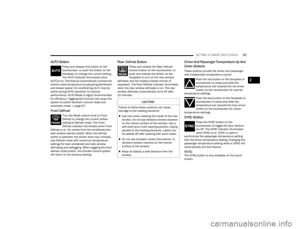
AUTO Button
Press and release this button on the
touchscreen, or push the button on the
faceplate, to change the current setting.
The AUTO indicator illuminates when
AUTO is on. This feature automatically controls the
interior cabin temperature by adjusting distribution
and blower speed. Air conditioning (A/C) may be
active during AUTO operation to improve
performance. AUTO Mode is highly recommended
for efficiency. Toggling this function will cause the
system to switch between manual mode and
automatic mode Ú page 67.
Front Defrost
Turn the Mode control knob to Front
Defrost to change the current airflow
setting to Defrost mode. The Front
Defrost indicator illuminates when Front
Defrost is on. Air comes from the windshield and
side window demist outlets. When the defrost
button is selected, the blower level may increase.
Use Defrost mode with maximum temperature
settings for best windshield and side window
defrosting and defogging. When toggling the front
defrost mode button, the Climate Control system
will return to the previous setting.
Rear Defrost Button
Press and release the Rear Defrost
Control button on the touchscreen, or
push and release the button on the
faceplate to turn on the rear window
defroster and the heated outside mirrors (if
equipped). The Rear Defrost indicator illuminates
when the rear window defroster is on. The rear
window defroster automatically turns off after
10 minutes.
Driver And Passenger Temperature Up And
Down Buttons
These buttons provide the driver and passenger
with independent temperature control.
Push the red button on the faceplate or
touchscreen or press and slide the
temperature bar towards the red arrow
button on the touchscreen for warmer
temperature settings.
Push the blue button on the faceplate or
touchscreen or press and slide the
temperature bar towards the blue arrow
button on the touchscreen for cooler
temperature settings.
SYNC Button
Press the SYNC button on the
touchscreen to toggle the Sync feature
on/off. The SYNC indicator illuminates
when SYNC is on. SYNC is used to
synchronize the passenger temperature setting
with the driver temperature setting. Changing the
passenger temperature setting while in SYNC will
automatically exit this feature.
NOTE:The SYNC button is only available on the touch-
screen.
CAUTION!
Failure to follow these cautions can cause
damage to the heating elements:
Use care when washing the inside of the rear
window. Do not use abrasive window cleaners
on the interior surface of the window. Use a
soft cloth and a mild washing solution, wiping
parallel to the heating elements. Labels can
be peeled off after soaking with warm water.
Do not use scrapers, sharp instruments, or
abrasive window cleaners on the interior
surface of the window.
Keep all objects a safe distance from the
window.
2
23_JT_OM_EN_USC_t.book Page 63
Page 92 of 448
90GETTING TO KNOW YOUR VEHICLE
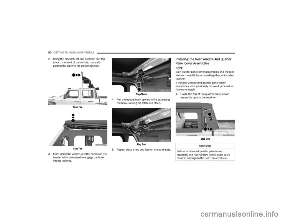
2. Using the side link, lift and push the soft top toward the front of the vehicle, manually
guiding the top into the closed position.
Step Two
Step Two
3. From inside the vehicle, pull the handle on the header latch downward to engage the hook
into its receiver.
Step Three
4. Pull the handle back upward while squeezing the hook, locking the latch into place.
Step Four
5. Repeat steps three and four on the other side.
Installing The Rear Window And Quarter
Panel Cover Assemblies
NOTE:Both quarter panel cover assemblies and the rear
window must ALL be removed together, or installed
together.
If the rear window and quarter panel cover
assemblies were previously removed, proceed as
follows to install:
1. Guide the top of the quarter panel cover assembly up into the retainer.
Step One
CAUTION!
Failure to follow all quarter panel cover
assembly and rear window install steps could
result in damage to the Soft Top or vehicle.
23_JT_OM_EN_USC_t.book Page 90
Page 93 of 448
GETTING TO KNOW YOUR VEHICLE91
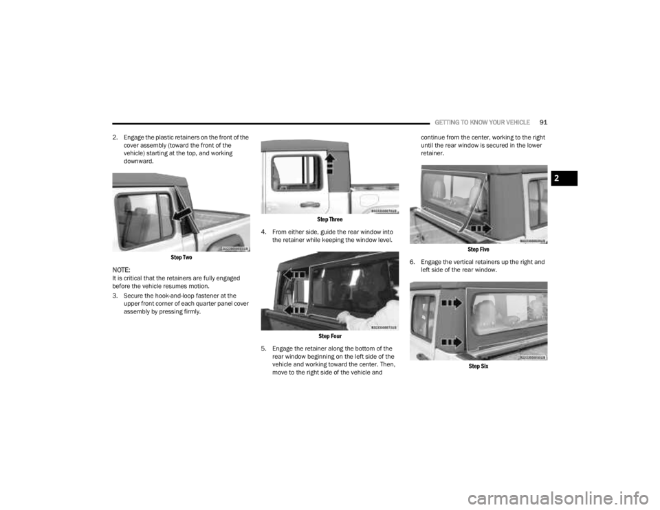
2. Engage the plastic retainers on the front of the cover assembly (toward the front of the
vehicle) starting at the top, and working
downward.
Step Two
NOTE:It is critical that the retainers are fully engaged
before the vehicle resumes motion.
3. Secure the hook-and-loop fastener at the upper front corner of each quarter panel cover
assembly by pressing firmly.
Step Three
4. From either side, guide the rear window into the retainer while keeping the window level.
Step Four
5. Engage the retainer along the bottom of the rear window beginning on the left side of the
vehicle and working toward the center. Then,
move to the right side of the vehicle and continue from the center, working to the right
until the rear window is secured in the lower
retainer.
Step Five
6. Engage the vertical retainers up the right and left side of the rear window.
Step Six
2
23_JT_OM_EN_USC_t.book Page 91