JEEP GRAND CHEROKEE 2003 WJ / 2.G Workshop Manual
GRAND CHEROKEE 2003 WJ / 2.G
JEEP
JEEP
https://www.carmanualsonline.info/img/16/7175/w960_7175-0.png
JEEP GRAND CHEROKEE 2003 WJ / 2.G Workshop Manual
Trending: egr, sensor, rack size, SAE, Turbo gasket, Fill, wipers
Page 1981 of 2199
FRONT DOOR WEATHERSTRIP
REMOVAL
(1) Remove A-pillar trim (Refer to 23 - BODY/IN-
TERIOR/A-PILLAR TRIM - REMOVAL).
(2) Remove B-pillar upper trim (Refer to 23 -
BODY/INTERIOR/B-PILLAR UPPER TRIM -
REMOVAL).
(3) Remove B-pillar lower trim (Refer to 23 -
BODY/INTERIOR/B-PILLAR LOWER TRIM -
REMOVAL).
(4) Pull weatherstrip from door opening flange.
INSTALLATION
(1) Position weatherstrip at corners.
(2) Move upward and around edge of door opening
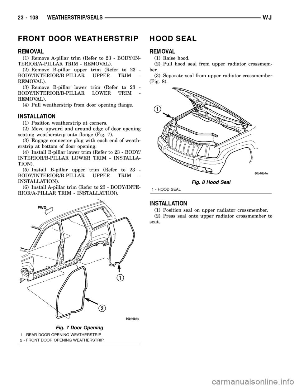
seating weatherstrip onto flange (Fig. 7).
(3) Engage connector plug with each end of weath-
erstrip at bottom of door opening.
(4) Install B-pillar lower trim (Refer to 23 - BODY/
INTERIOR/B-PILLAR LOWER TRIM - INSTALLA-
TION).
(5) Install B-pillar upper trim (Refer to 23 -
BODY/INTERIOR/B-PILLAR UPPER TRIM -
INSTALLATION).
(6) Install A-pillar trim (Refer to 23 - BODY/INTE-
RIOR/A-PILLAR TRIM - INSTALLATION).
HOOD SEAL
REMOVAL
(1) Raise hood.
(2) Pull hood seal from upper radiator crossmem-
ber.
(3) Separate seal from upper radiator crossmember
(Fig. 8).
INSTALLATION
(1) Position seal on upper radiator crossmember.
(2) Press seal onto upper radiator crossmember to
seat.
Fig. 7 Door Opening
1 - REAR DOOR OPENING WEATHERSTRIP
2 - FRONT DOOR OPENING WEATHERSTRIP
Fig. 8 Hood Seal
1 - HOOD SEAL
23 - 108 WEATHERSTRIP/SEALSWJ
Page 1982 of 2199
LIFTGATE OPENING
WEATHERSTRIP
REMOVAL
(1) Pull seal away from flange around edge of lift-
gate opening.
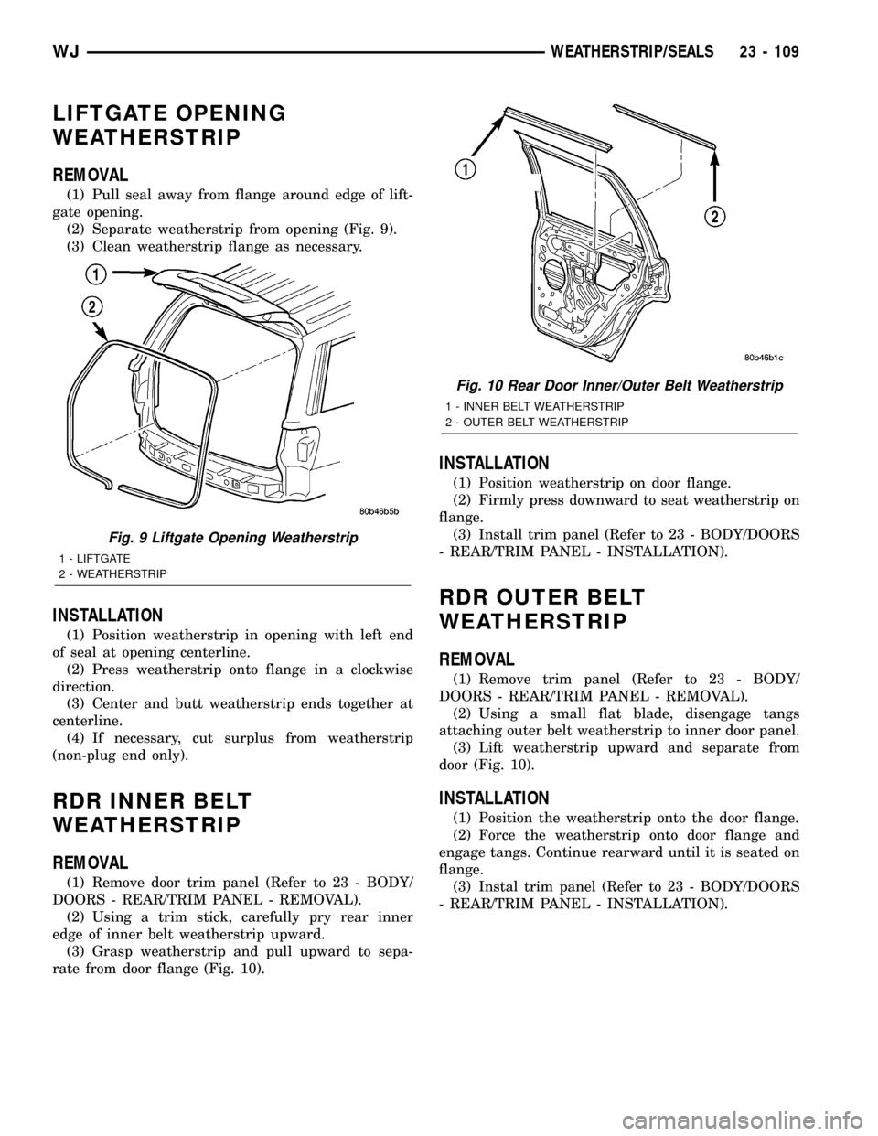
(2) Separate weatherstrip from opening (Fig. 9).
(3) Clean weatherstrip flange as necessary.
INSTALLATION
(1) Position weatherstrip in opening with left end
of seal at opening centerline.
(2) Press weatherstrip onto flange in a clockwise
direction.
(3) Center and butt weatherstrip ends together at
centerline.
(4) If necessary, cut surplus from weatherstrip
(non-plug end only).
RDR INNER BELT
WEATHERSTRIP
REMOVAL
(1) Remove door trim panel (Refer to 23 - BODY/
DOORS - REAR/TRIM PANEL - REMOVAL).
(2) Using a trim stick, carefully pry rear inner
edge of inner belt weatherstrip upward.
(3) Grasp weatherstrip and pull upward to sepa-
rate from door flange (Fig. 10).
INSTALLATION
(1) Position weatherstrip on door flange.
(2) Firmly press downward to seat weatherstrip on
flange.
(3) Install trim panel (Refer to 23 - BODY/DOORS
- REAR/TRIM PANEL - INSTALLATION).
RDR OUTER BELT
WEATHERSTRIP
REMOVAL
(1) Remove trim panel (Refer to 23 - BODY/
DOORS - REAR/TRIM PANEL - REMOVAL).
(2) Using a small flat blade, disengage tangs
attaching outer belt weatherstrip to inner door panel.
(3) Lift weatherstrip upward and separate from
door (Fig. 10).
INSTALLATION
(1) Position the weatherstrip onto the door flange.
(2) Force the weatherstrip onto door flange and
engage tangs. Continue rearward until it is seated on
flange.
(3) Instal trim panel (Refer to 23 - BODY/DOORS
- REAR/TRIM PANEL - INSTALLATION).
Fig. 9 Liftgate Opening Weatherstrip
1 - LIFTGATE
2 - WEATHERSTRIP
Fig. 10 Rear Door Inner/Outer Belt Weatherstrip
1 - INNER BELT WEATHERSTRIP
2 - OUTER BELT WEATHERSTRIP
WJWEATHERSTRIP/SEALS 23 - 109
Page 1983 of 2199

RDR SECONDARY
WEATHERSTRIP
REMOVAL
The rear door secondary weatherstrip is attached
to the door shutface with push-in fasteners.
(1) Open door.
(2) Using a trim panel removal tool, remove
push-in fasteners attaching secondary weatherstrip
to door shutface.
(3) Separate secondary weatherstrip from door
(Fig. 11).
INSTALLATION
(1) Clean contact area as necessary.
(2)
Position secondary weatherstrip on door shutface.
(3) Install push-in fasteners attaching secondary
weatherstrip to door shutface.
REAR DOOR WEATHERSTRIP
REMOVAL
(1) Remove C-pillar trim (Refer to 23 - BODY/IN-
TERIOR/C-PILLAR TRIM - REMOVAL).
(2) Remove B-pillar upper trim (Refer to 23 -
BODY/INTERIOR/B-PILLAR UPPER TRIM -
REMOVAL).
(3) Remove B-pillar lower trim(Refer to 23 -
BODY/INTERIOR/B-PILLAR LOWER TRIM -
REMOVAL).
(4) Remove screws at front of quarter trim panel.
(5) Pull weatherstrip from door opening flange.
INSTALLATION
(1) Position weatherstrip at corners.
(2) Move upward and around edge of door opening
seating weatherstrip onto flange (Fig. 7).(3) Engage connector plug with each end of weath-
erstrip at bottom of door opening.
(4) Install screws at front of quarter trim panel.
(5)
Install B-pillar lower trim (Refer to 23 - BODY/IN-
TERIOR/B-PILLAR LOWER TRIM - INSTALLATION).
(6) Install B-pillar upper trim (Refer to 23 -
BODY/INTERIOR/B-PILLAR UPPER TRIM -
INSTALLATION).
(7) Install C-pillar trim (Refer to 23 - BODY/INTE-
RIOR/C-PILLAR TRIM - INSTALLATION).
ROOF RAIL WEATHERSTRIP /
RETAINR
REMOVAL
(1) Open front and rear doors.
(2) Remove secondary seal from retainer to access
the screws holding the retainer to the A pillar and
roof panel.
(3) Remove the screws holding the retainer in
place (Fig. 12).
(4) Remove the retainer.
INSTALLATION
(1) Position the retainer on the A pillar and roof
panel.
(2) Align the screw holes and install the screws.
(3) Install secondary seal.
Fig. 11 Rear Door Secondary Weatherstrip
1 - SECONDARY WEATHERSTRIP
Fig. 12 Upper Body Seal With Retainer
1 - ROOF RAIL WEATHERSTRIP
2 - RETAINER
3 - SCREW
4 - BLOCKER
23 - 110 WEATHERSTRIP/SEALSWJ
Page 1984 of 2199
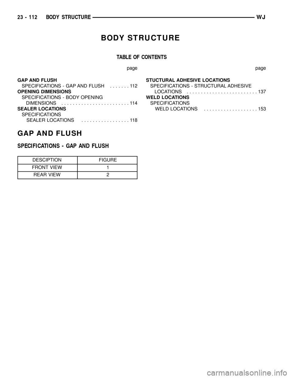
BODY STRUCTURE
TABLE OF CONTENTS
page page
GAP AND FLUSH
SPECIFICATIONS - GAP AND FLUSH.......112
OPENING DIMENSIONS
SPECIFICATIONS - BODY OPENING
DIMENSIONS........................114
SEALER LOCATIONS
SPECIFICATIONS
SEALER LOCATIONS.................118STUCTURAL ADHESIVE LOCATIONS
SPECIFICATIONS - STRUCTURAL ADHESIVE
LOCATIONS.........................137
WELD LOCATIONS
SPECIFICATIONS
WELD LOCATIONS...................153
GAP AND FLUSH
SPECIFICATIONS - GAP AND FLUSH
DESCIPTION FIGURE
FRONT VIEW 1
REAR VIEW 2
23 - 112 BODY STRUCTUREWJ
Page 1985 of 2199
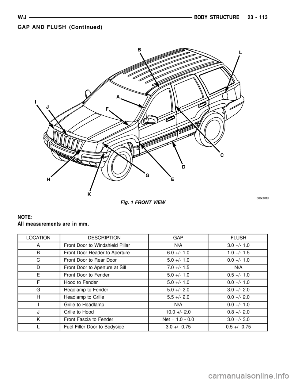
NOTE:
All measurements are in mm.
LOCATION DESCRIPTION GAP FLUSH
A Front Door to Windshield Pillar N/A 3.0 +/- 1.0
B Front Door Header to Aperture 6.0 +/- 1.0 1.0 +/- 1.5
C Front Door to Rear Door 5.0 +/- 1.0 0.0 +/- 1.0
D Front Door to Aperture at Sill 7.0 +/- 1.5 N/A
E Front Door to Fender 5.0 +/- 1.0 0.5 +/- 1.0
F Hood to Fender 5.0 +/- 1.0 0.0 +/- 1.0
G Headlamp to Fender 5.0 +/- 2.0 3.0 +/- 2.0
H Headlamp to Grille 5.5 +/- 2.0 0.0 +/- 2.0
I Grille to Headlamp N/A 0.0 +/- 1.0
J Grille to Hood 10.0 +/- 2.0 0.8 +/- 2.0
K Front Fascia to Fender Net + 1.0 - 0.0 3.0 +/- 3.0
L Fuel Filler Door to Bodyside 3.0 +/- 0.75 0.5 +/- 0.75
Fig. 1 FRONT VIEW
WJBODY STRUCTURE 23 - 113
GAP AND FLUSH (Continued)
Page 1986 of 2199
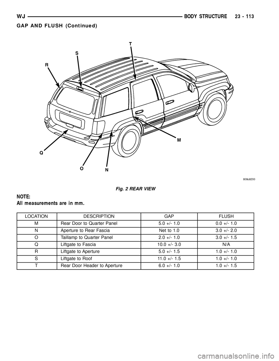
NOTE:
All measurements are in mm.
LOCATION DESCRIPTION GAP FLUSH
M Rear Door to Quarter Panel 5.0 +/- 1.0 0.0 +/- 1.0
N Aperture to Rear Fascia Net to 1.0 3.0 +/- 2.0
O Taillamp to Quarter Panel 2.0 +/- 1.0 3.0 +/- 1.5
Q Liftgate to Fascia 10.0 +/- 3.0 N/A
R Liftgate to Aperture 5.0 +/- 1.5 1.0 +/- 1.0
S Liftgate to Roof 11.0 +/- 1.5 1.0 +/- 1.0
T Rear Door Header to Aperture 6.0 +/- 1.0 1.0 +/- 1.5
Fig. 2 REAR VIEW
WJBODY STRUCTURE 23 - 113
GAP AND FLUSH (Continued)
Page 1987 of 2199
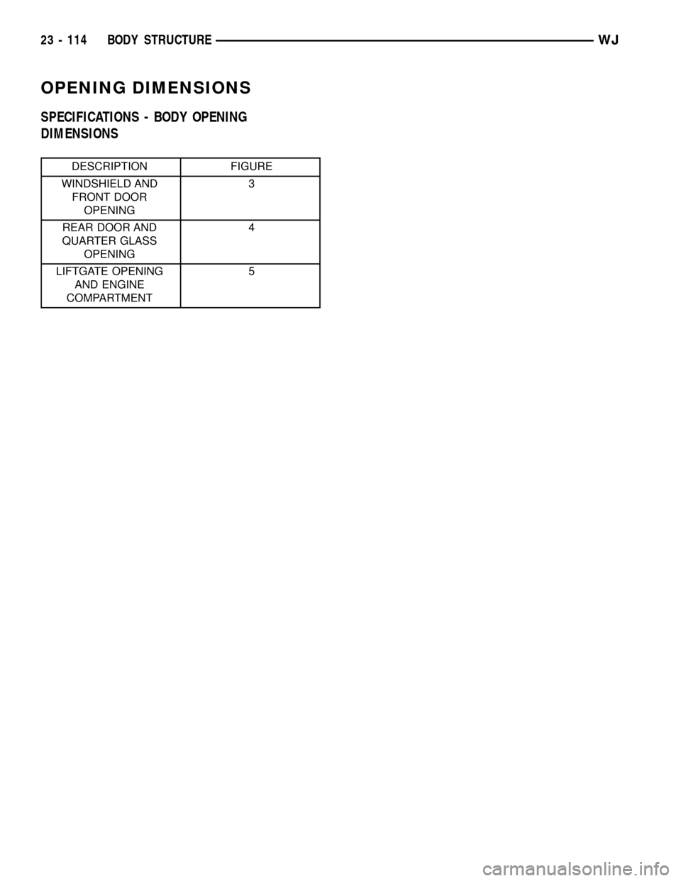
OPENING DIMENSIONS
SPECIFICATIONS - BODY OPENING
DIMENSIONS
DESCRIPTION FIGURE
WINDSHIELD AND
FRONT DOOR
OPENING3
REAR DOOR AND
QUARTER GLASS
OPENING4
LIFTGATE OPENING
AND ENGINE
COMPARTMENT5
23 - 114 BODY STRUCTUREWJ
Page 1988 of 2199
Fig. 3 WINDSHIELD AND FRONT DOOR OPENING
WJBODY STRUCTURE 23 - 115
OPENING DIMENSIONS (Continued)
2002 WJ Service Manual
Publication No. 81-370-02064
TSB 26-11-01 November 2001
Page 1989 of 2199
Fig. 4 REAR DOOR AND QUARTER GLASS OPENING
23 - 116 BODY STRUCTUREWJ
OPENING DIMENSIONS (Continued)
Page 1990 of 2199
Fig. 5 LIFTGATE OPENING AND ENGINE COMPARTMENT
WJBODY STRUCTURE 23 - 117
OPENING DIMENSIONS (Continued)
Trending: Wiring schematics, Central lock, coolant capacity, Coolant drain hose, frame, sunroof, wheel torque


