headlamp JEEP GRAND CHEROKEE 2012 Owner handbook (in English)
[x] Cancel search | Manufacturer: JEEP, Model Year: 2012, Model line: GRAND CHEROKEE, Model: JEEP GRAND CHEROKEE 2012Pages: 380, PDF Size: 3.21 MB
Page 185 of 380
Remote Unlock Sequence
WhenUnlock Driver Door Only On 1st Press
is selected, only the driver’s door will unlock on
the first press of the RKE transmitter UNLOCK
button. When Driver Door 1st Press is selected,
you must press the RKE transmitter UNLOCK
button twice to unlock the passenger’s doors.
When Unlock All Doors On 1st Press is
selected, all of the doors will unlock on the first
press of the RKE transmitter UNLOCK button.
To make your selection, scroll up or down until
the preferred setting is highlighted, then press
and release the SELECT button until a check-
mark appears next to the setting, showing that
the setting has been selected.
NOTE:
If the vehicle is equipped with Keyless
Enter-N-Go (Passive Entry) and the EVIC is
programmed to Unlock All Doors 1st Press,
all doors will unlock no matter which Pas-
sive Entry equipped door handle is grasped.
If Driver Door 1st Press is programmed, only
the driver’s door will unlock when the driv-
er’s door is grasped. With Passive Entry, if
Driver Door 1st Press is programmed touch-
ing the handle more than once will only result in the driver’s door opening. If driver
door first is selected, once the driver door is
opened, the interior door lock/unlock switch
can be used to unlock all doors (or use RKE
transmitter).
RKE Linked To Memory
When this feature is selected, you can use your
RKE transmitter to recall one of two pre-
programmed memory profiles. Each memory
profile contains desired position settings for the
driver seat, side mirror, adjustable pedals (if
equipped), power tilt and telescopic steering
column (if equipped), and a set of desired radio
station presets. When OFF is selected, only the
MEMORY switch on the driver’s door trim panel
will recall memory profiles. To make your selec-
tion, press and release the SELECT button a
check-mark appears next to the feature show-
ing the system has been activated or the
check-mark is removed showing the system
has been deactivated. Refer to “Driver Memory
Seat” in “Understanding The Features Of Your
Vehicle.”
Flash Lamps With Lock
When this feature is selected, the front and rear
turn signals will flash when the doors are locked
or unlocked with the RKE transmitter. To make
your selection, press and release the SELECT
button until a check-mark appears next to the
feature showing the system has been activated
or the check-mark is removed showing the
system has been deactivated.
Headlamp Off Delay
When this feature is selected, the driver can
choose to have the headlights remain on for 0,
30, 60, or 90 seconds when exiting the vehicle.
To make your selection, scroll up or down until
the preferred setting is highlighted, then press
and release the SELECT button until a check-
mark appears next to the setting, showing that
the setting has been selected.
Headlamps with Wipers (Available with
Automatic Headlamps Only)
When this feature is selected, and the headlight
switch is in the AUTO position, the headlights
will turn on approximately 10 seconds after the
wipers are turned on. The headlights will also
turn off when the wipers are turned off if they
were turned on by this feature. To make your
181
Page 269 of 380

WARNING!
Do not use alcohol or gasoline as a fuel-
blending agent. They can be unstable under
certain conditions and hazardous or explosive
when mixed with diesel fuel.
Diesel fuel is seldom completely free of water.
To prevent fuel system trouble, drain the accu-
mulated water from the fuel/water separator
using the provided fuel/water separator drain. If
you buy good quality fuel and follow the cold
weather advice above, fuel conditioners should
not be required in your vehicle. If available in
your area, a high cetane “premium” diesel fuel
may offer improved cold-starting and warm-up
performance.
ADDING FUEL
Fuel Filler Cap (Gas Cap)
The gas cap is located behind the locking fuel
filler door, on the driver’s side of the vehicle. If
the gas cap is lost or damaged, be sure the
replacement cap is for use with this vehicle.
1. Press the fuel filler door release switch (lo-
cated under the headlamp switch). 2. Open the fuel filler door, and remove the fuel
filler cap.
CAUTION!
•
Damage to the fuel system or emission
control system could result from using an
improper fuel cap (gas cap). A poorly fitting
cap could let impurities into the fuel system.
Also, a poorly fitting aftermarket cap can
cause the “Malfunction Indicator Light
(MIL)” to illuminate, due to fuel vapors
escaping from the system.
• A poorly fitting gas cap may cause the MIL
to turn on.
• To avoid fuel spillage and overfilling, do not
“top off” the fuel tank after filling.
WARNING!
•Never have any smoking materials lit in or
near the vehicle when the gas cap is re-
moved or the tank is being filled.
• Never add fuel when the engine is running.
This is in violation of most state and federal
fire regulations and may cause the mal-
function indicator light to turn on.
(Continued)
Fuel Filler Door Release Switch
Fuel Filler Cap
265
Page 300 of 380
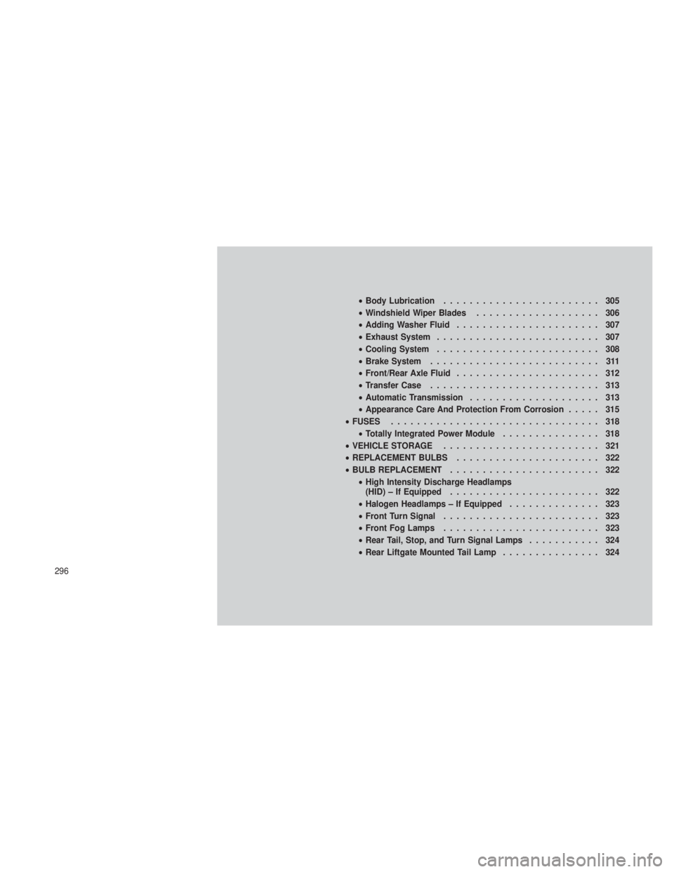
•Body Lubrication ........................ 305
• Windshield Wiper Blades ................... 306
• Adding Washer Fluid ...................... 307
• Exhaust System ......................... 307
• Cooling System ......................... 308
• Brake System .......................... 311
• Front/Rear Axle Fluid ...................... 312
• Transfer Case .......................... 313
• Automatic Transmission .................... 313
• Appearance Care And Protection From Corrosion ..... 315
• FUSES ................................ 318
• Totally Integrated Power Module ............... 318
• VEHICLE STORAGE ........................ 321
• REPLACEMENT BULBS ...................... 322
• BULB REPLACEMENT ....................... 322
• High Intensity Discharge Headlamps
(HID) – If Equipped ....................... 322
• Halogen Headlamps – If Equipped .............. 323
• Front Turn Signal ........................ 323
• Front Fog Lamps ........................ 323
• Rear Tail, Stop, and Turn Signal Lamps ........... 324
• Rear Liftgate Mounted Tail Lamp ............... 324
296
Page 323 of 380
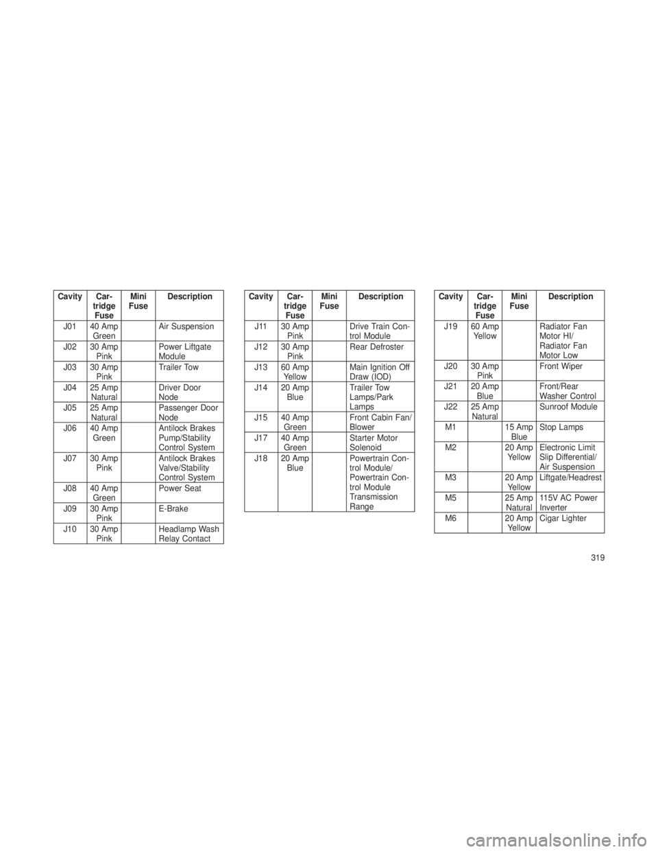
Cavity Car-tridgeFuse Mini
Fuse Description
J01 40 Amp Green Air Suspension
J02 30 Amp Pink Power Liftgate
Module
J03 30 Amp Pink Trailer Tow
J04 25 Amp Natural Driver Door
Node
J05 25 Amp Natural Passenger Door
Node
J06 40 Amp Green Antilock Brakes
Pump/Stability
Control System
J07 30 Amp Pink Antilock Brakes
Valve/Stability
Control System
J08 40 Amp Green Power Seat
J09 30 Amp Pink E-Brake
J10 30 Amp Pink Headlamp Wash
Relay ContactCavity Car-
tridgeFuse Mini
Fuse Description
J11 30 Amp Pink Drive Train Con-
trol Module
J12 30 Amp Pink Rear Defroster
J13 60 Amp Yellow Main Ignition Off
Draw (IOD)
J14 20 Amp Blue Trailer Tow
Lamps/Park
Lamps
J15 40 Amp Green Front Cabin Fan/
Blower
J17 40 Amp Green Starter Motor
Solenoid
J18 20 Amp Blue Powertrain Con-
trol Module/
Powertrain Con-
trol Module
Transmission
RangeCavity Car-
tridgeFuse Mini
Fuse Description
J19 60 Amp Yellow Radiator Fan
Motor HI/
Radiator Fan
Motor Low
J20 30 Amp Pink Front Wiper
J21 20 Amp Blue Front/Rear
Washer Control
J22 25 Amp Natural Sunroof Module
M1 15 Amp
Blue Stop Lamps
M2 20 Amp
Yellow Electronic Limit
Slip Differential/
Air Suspension
M3 20 Amp
Yellow Liftgate/Headrest
M5 25 Amp
Natural 115V AC Power
Inverter
M6 20 Amp
Yellow Cigar Lighter
319
Page 326 of 380
•Anytime you store your vehicle, or keep it out
of service (i.e. vacation) for two weeks or
more, run the air conditioning system at idle
for about five minutes in the fresh air and
high blower setting. This will ensure ad-
equate system lubrication to minimize the
possibility of compressor damage when the
system is started again.
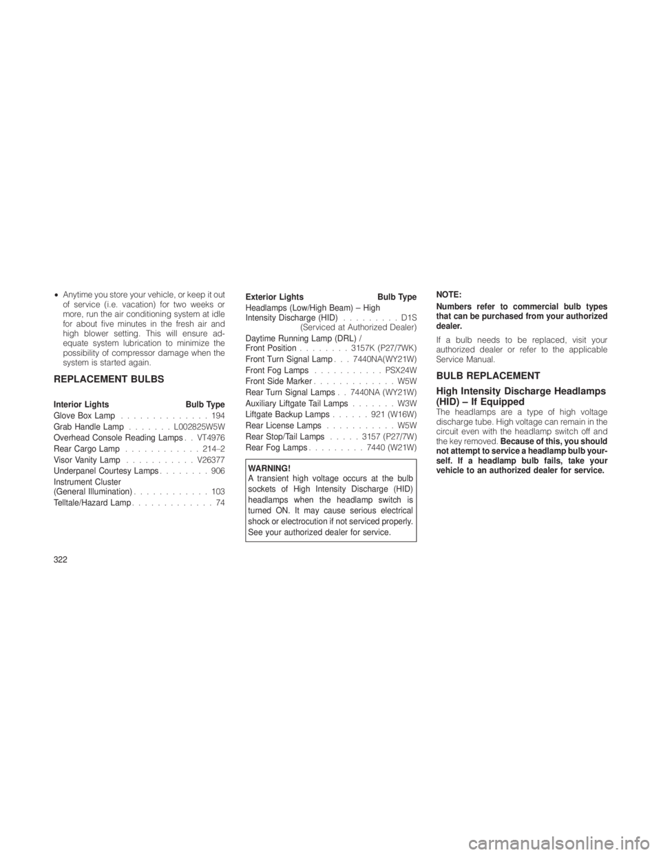
REPLACEMENT BULBS
Interior Lights Bulb Type
Glove Box Lamp ..............194
Grab Handle Lamp .......L002825W5W
Overhead Console Reading Lamps . . VT4976
Rear Cargo Lamp ............ 214–2
Visor Vanity Lamp ...........V26377
Underpanel Courtesy Lamps ........906
Instrument Cluster
(General Illumination) ............103
Telltale/Hazard Lamp .............74 Exterior Lights
Bulb Type
Headlamps (Low/High Beam) – High
Intensity Discharge (HID) .........D1S
(Serviced at Authorized Dealer)
Daytime Running Lamp (DRL) /
Front Position ........3157K (P27/7WK)
Front Turn Signal Lamp . . . 7440NA(WY21W)
Front Fog Lamps ........... PSX24W
Front Side Marker .............W5W
Rear Turn Signal Lamps . . 7440NA (WY21W)
Auxiliary Liftgate Tail Lamps .......W3W
Liftgate Backup Lamps ......921(W16W)
Rear License Lamps ...........W5W
Rear Stop/Tail Lamps .....3157 (P27/7W)
Rear Fog Lamps .........7440 (W21W)
WARNING!
A transient high voltage occurs at the bulb
sockets of High Intensity Discharge (HID)
headlamps when the headlamp switch is
turned ON. It may cause serious electrical
shock or electrocution if not serviced properly.
See your authorized dealer for service. NOTE:
Numbers refer to commercial bulb types
that can be purchased from your authorized
dealer.
If a bulb needs to be replaced, visit your
authorized dealer or refer to the applicable
Service Manual.
BULB REPLACEMENT
High Intensity Discharge Headlamps
(HID) – If Equipped
The headlamps are a type of high voltage
discharge tube. High voltage can remain in the
circuit even with the headlamp switch off and
the key removed.
Because of this, you should
not attempt to service a headlamp bulb your-
self. If a headlamp bulb fails, take your
vehicle to an authorized dealer for service.
322
Page 327 of 380
WARNING!
A transient high voltage occurs at the bulb
sockets of High Intensity Discharge (HID)
headlamps when the headlamp switch is
turned ON. It may cause serious electrical
shock or electrocution if not serviced properly.
See your authorized dealer for service.
NOTE:
On vehicles equipped with High Intensity
Discharge (HID) headlamps, when the head-
lamps are turned on, there is a blue hue to
the lamps. This diminishes and becomes
more white after approximately 10 seconds,
as the system charges.
Halogen Headlamps – If Equipped
1. Open the hood.
2. Turn the low or high beam bulb one–quarter
turn counterclockwise to remove from housing.
3. Disconnect the electrical connector and re-
place the bulb.
CAUTION!
Do not touch the new bulb with your fingers.
Oil contamination will severely shorten bulb
life. If the bulb comes in contact with any oily
surface, clean the bulb with rubbing alcohol.
Front Turn Signal
1. Open the hood.
2. Turn the turn signal bulb one–quarter turn
counterclockwise to remove from housing.
3. Disconnect the electrical connector and re-
place the bulb.
CAUTION!
Do not touch the new bulb with your fingers.
Oil contamination will severely shorten bulb
life. If the bulb comes in contact with any oily
surface, clean the bulb with rubbing alcohol.
Front Fog Lamps
1. Reach through the cutout in the splash
shield and disconnect the wiring harness from
the fog lamp connector. 2. Firmly grasp the bulb by the two latches and
squeeze them together to unlock the bulb from
the back of the front fog lamp housing.
3. Pull the bulb straight out from the keyed
opening in the housing.
CAUTION!
•
Do not touch the new bulb with your fin-
gers. Oil contamination will severely
shorten bulb life. If the bulb comes in
contact with any oily surface, clean the bulb
with rubbing alcohol.
• Always use the correct bulb size and type
for replacement. An incorrect bulb size or
type may overheat and cause damage to
the lamp, the socket or the lamp wiring.
4. Align the index tabs of the front fog lamp
bulb with the slots in the collar of the bulb
opening on the back of the front fog lamp
housing.
5. Insert the bulb into the housing until the
index tabs are engaged in the slots of the collar.
323