fuse JEEP GRAND CHEROKEE 2013 Owner handbook (in English)
[x] Cancel search | Manufacturer: JEEP, Model Year: 2013, Model line: GRAND CHEROKEE, Model: JEEP GRAND CHEROKEE 2013Pages: 408, PDF Size: 3.21 MB
Page 53 of 408
Air Bag Warning LightYou will want to have the air bags
ready to inflate for your protection
in a collision. The Air Bag Warning
Light monitors the internal circuits
and interconnecting wiring associ-
ated with air bag system electrical
components. While the air bag system is de-
signed to be maintenance free, if any of the
following occurs, have an authorized dealer
service the air bag system immediately.
• The Air Bag Warning Light does not come on
during the four to eight seconds when the
ignition switch is first turned to the ON/RUN
position.
• The Air Bag Warning Light remains on after
the four to eight-second interval.
• The Air Bag Warning Light comes on inter-
mittently or remains on while driving. NOTE:
If the speedometer, tachometer, or any en-
gine related gauges are not working, the
Occupant Restraint Controller (ORC) may
also be disabled. The air bags may not be
ready to inflate for your protection. Promptly
check the fuse block for blown fuses. Refer
to the label located on the inside of the fuse
block cover for the proper air bag fuses. See
your authorized dealer if the fuse is good.
Event Data Recorder (EDR)This vehicle is equipped with an event data
recorder (EDR). The main purpose of an EDR is
to record, in certain crash or near crash-like
situations, such as an air bag deployment or
hitting a road obstacle, data that will assist in
understanding how a vehicle’s systems per-
formed. The EDR is designed to record data
related to vehicle dynamics and safety systems
for a short period of time, typically 30 seconds
or less. The EDR in this vehicle is designed to
record such data as:
•
How various systems in your vehicle were
operating; •
Whether or not the driver and passenger
safety belts were buckled/fastened;
• How far (if at all) the driver was depressing
the accelerator and/or brake pedal; and,
• How fast the vehicle was traveling.
These data can help provide a better under-
standing of the circumstances in which crashes
and injuries occur.
NOTE:
EDR data are recorded by your vehicle only
if a non-trivial crash situation occurs; no
data are recorded by the EDR under normal
driving conditions and no personal data
(e.g., name, gender, age, and crash location)
are recorded. However, other parties, such
as law enforcement, could combine the EDR
data with the type of personally identifying
data routinely acquired during a crash in-
vestigation.
49
Page 150 of 408
If the buffeting occurs with the sunroof open,
adjust the sunroof opening to minimize the
buffeting or open any window.
Sunroof MaintenanceUse only a non-abrasive cleaner and a soft
cloth to clean the glass panel.
Ignition OFF OperationThe power sunroof switches can be programmed to
remain active for up to approximately ten minutes
after the ignition switch has been turned OFF.
Refer to “Electronic Vehicle Information Center
(EVIC)/Customer-Programmable Features (Sys-
tem Setup)” in “Understanding Your Instrument
Panel” for further information.
NOTE:
Opening either front door will cancel this
feature.
Sunroof Fully ClosedPress the switch forward and release to ensure
that the sunroof is fully closed.
ELECTRICAL POWER
OUTLETS
Your vehicle is equipped with 12 Volt (13 Amp)
power outlets that can be used to power cellular
phones, small electronics and other low pow-
ered electrical accessories. The power outlets
are labeled with either a “key” or a “battery”
symbol to indicate how the outlet is powered.
Power outlets labeled with a “key” are powered
when the ignition switch is in the ON or ACC
position, while the outlets labeled with a “bat-
tery” are connected directly to the battery and
powered at all times.
NOTE:
•All accessories connected to the “bat-
tery” powered outlets should be removed
or turned off when the vehicle is not in
use to protect the battery against dis-
charge.
• To ensure proper operation a MOPAR®
knob and element must be used.
CAUTION!
Power outlets are designed for accessory
plugs only. Do not insert any other object in
the power outlets as this will damage the
outlet and blow the fuse. Improper use of the
power outlet can cause damage not covered
by your New Vehicle Limited Warranty.
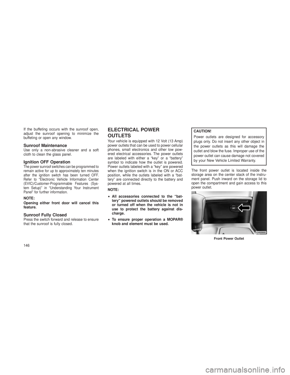
The front power outlet is located inside the
storage area on the center stack of the instru-
ment panel. Push inward on the storage lid to
open the compartment and gain access to this
power outlet.
Front Power Outlet
146
Page 151 of 408
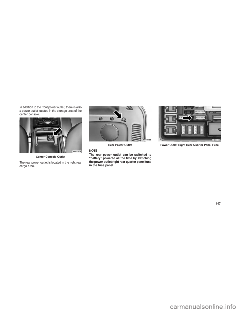
In addition to the front power outlet, there is also
a power outlet located in the storage area of the
center console.
The rear power outlet is located in the right rear
cargo area.NOTE:
The rear power outlet can be switched to
“battery” powered all the time by switching
the power outlet right rear quarter panel fuse
in the fuse panel.
Center Console Outlet
Rear Power OutletPower Outlet Right Rear Quarter Panel Fuse
147
Page 152 of 408
WARNING!
To avoid serious injury or death:
•Only devices designed for use in this type
of outlet should be inserted into any 12 Volt
outlet.
• Do not touch with wet hands.
• Close the lid when not in use and while
driving the vehicle.
• If this outlet is mishandled, it may cause an
electric shock and failure.
CAUTION!
•Many accessories that can be plugged in
draw power from the vehicle’s battery,
even when not in use (i.e., cellular phones,
etc.). Eventually, if plugged in long enough,
the vehicle’s battery will discharge suffi-
ciently to degrade battery life and/or pre-
vent the engine from starting.
(Continued)
CAUTION!(Continued)
•Accessories that draw higher power (i.e.,
coolers, vacuum cleaners, lights, etc.) will
degrade the battery even more quickly.
Only use these intermittently and with
greater caution.
• After the use of high power draw accesso-
ries, or long periods of the vehicle not
being started (with accessories still
plugged in), the vehicle must be driven a
sufficient length of time to allow the gen-
erator to recharge the vehicle’s battery.
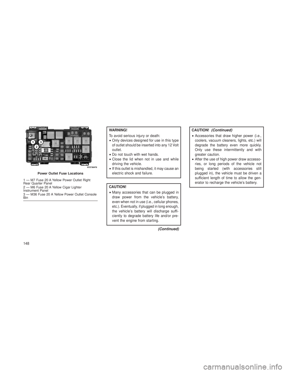
Power Outlet Fuse Locations
1 — M7 Fuse 20 A Yellow Power Outlet Right
Rear Quarter Panel
2 — M6 Fuse 20 A Yellow Cigar Lighter
Instrument Panel
3 — M36 Fuse 20 A Yellow Power Outlet Console
Bin
148
Page 312 of 408
•Exhaust System ............................. .320
• Cooling System .............................. .321
• Brake System ............................... .324
• Front/Rear Axle Fluid .......................... .325
• Transfer Case ............................... .326
• Automatic Transmission ......................... .326
• Appearance Care And Protection From Corrosion ..........328
•FUSES ......................................331•Totally Integrated Power Module .....................331•VEHICLE STORAGE .............................335
• REPLACEMENT BULBS ...........................336
• BULB REPLACEMENT ............................336
•High Intensity Discharge Headlamps (HID) – If Equipped ......336
• Halogen Headlamps – If Equipped ....................337
• Front Turn Signal ............................. .337
• Front Fog Lamps ............................. .337
• Rear Tail, Stop, and Turn Signal Lamps ................338
• Rear Liftgate Mounted Tail Lamp .....................338
• Rear Fascia Mounted Fog Lamp .....................339
• Center High-Mounted Stop Lamp (CHMSL) ...............339
• Rear License Lamp ............................ .339
•FLUID CAPACITIES ..............................340
• FLUIDS, LUBRICANTS AND GENUINE PARTS .............341
•Engine ................................... .341
• Chassis ................................... .342
308
Page 313 of 408
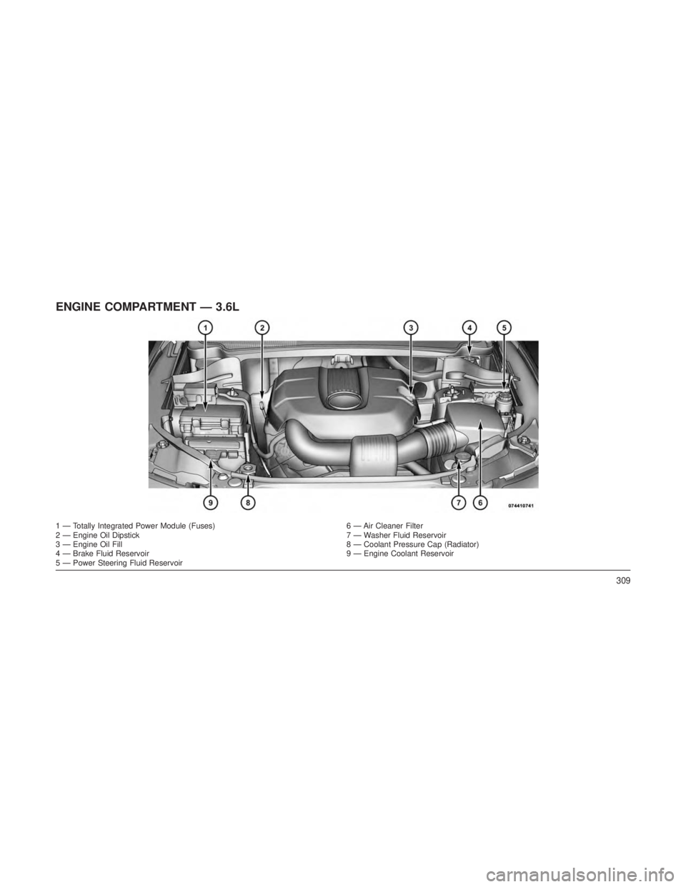
ENGINE COMPARTMENT — 3.6L
1 — Totally Integrated Power Module (Fuses)6 — Air Cleaner Filter
2 — Engine Oil Dipstick 7 — Washer Fluid Reservoir
3 — Engine Oil Fill 8 — Coolant Pressure Cap (Radiator)
4 — Brake Fluid Reservoir 9 — Engine Coolant Reservoir
5 — Power Steering Fluid Reservoir
309
Page 314 of 408
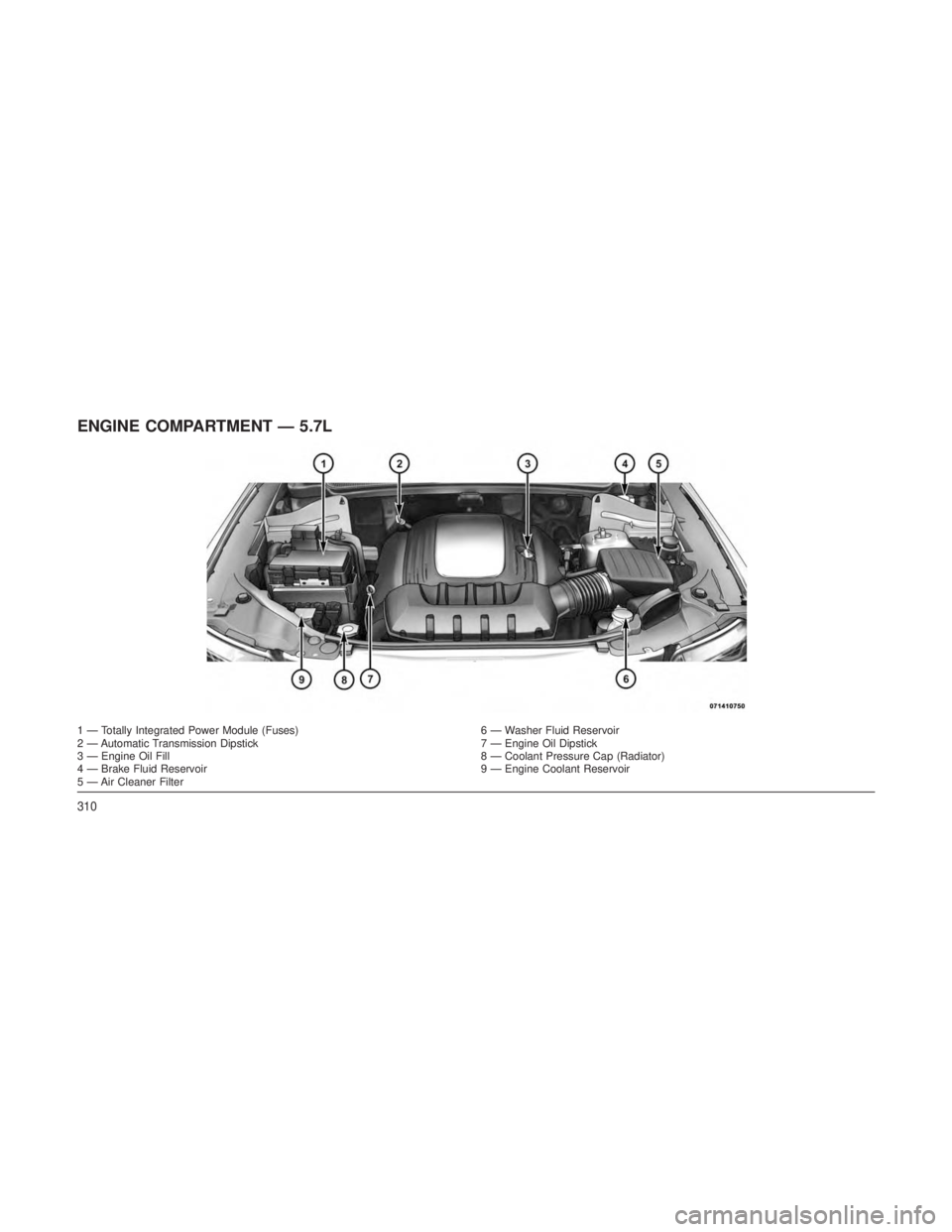
ENGINE COMPARTMENT — 5.7L
1 — Totally Integrated Power Module (Fuses)6 — Washer Fluid Reservoir
2 — Automatic Transmission Dipstick 7 — Engine Oil Dipstick
3 — Engine Oil Fill 8 — Coolant Pressure Cap (Radiator)
4 — Brake Fluid Reservoir 9 — Engine Coolant Reservoir
5 — Air Cleaner Filter
310
Page 315 of 408
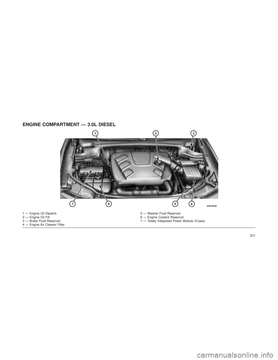
ENGINE COMPARTMENT — 3.0L DIESEL
1 — Engine Oil Dipstick5 — Washer Fluid Reservoir
2 — Engine Oil Fill 6 — Engine Coolant Reservoir
3 — Brake Fluid Reservoir 7 — Totally Integrated Power Module (Fuses)
4 — Engine Air Cleaner Filter
311
Page 335 of 408
Glass Surfaces
All glass surfaces should be cleaned on a
regular basis with MOPAR® Glass Cleaner, or
any commercial household-type glass cleaner.
Never use an abrasive type cleaner. Use cau-
tion when cleaning the inside rear window
equipped with electric defrosters or the right
rear quarter window equipped with the radio
antenna. Do not use scrapers or other sharp
instrument that may scratch the elements.
When cleaning the rear view mirror, spray
cleaner on the towel or rag that you are using.
Do not spray cleaner directly on the mirror.
Cleaning Plastic Instrument Cluster Lenses
The lenses in front of the instruments in this
vehicle are molded in clear plastic. When clean-
ing the lenses, care must be taken to avoid
scratching the plastic.
1. Clean with a wet soft rag. A mild soap
solution may be used, but do not use high
alcohol content or abrasive cleaners. If soap is
used, wipe clean with a clean damp rag.
2. Dry with a soft cloth.Seat Belt Maintenance
Do not bleach, dye or clean the belts with
chemical solvents or abrasive cleaners. This will
weaken the fabric. Sun damage can also
weaken the fabric.
If the belts need cleaning, use a mild soap
solution or lukewarm water. Do not remove the
belts from the car to wash them. Dry with a soft
cloth.
Replace the belts if they appear frayed or worn
or if the buckles do not work properly.
FUSES
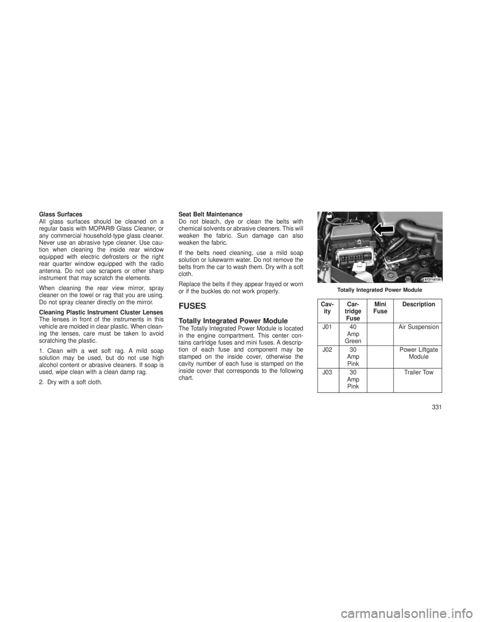
Totally Integrated Power ModuleThe Totally Integrated Power Module is located
in the engine compartment. This center con-
tains cartridge fuses and mini fuses. A descrip-
tion of each fuse and component may be
stamped on the inside cover, otherwise the
cavity number of each fuse is stamped on the
inside cover that corresponds to the following
chart.
Cav-
ity Car-
tridge Fuse Mini
Fuse Description
J01 40 Amp
Green Air Suspension
J02 30 AmpPink Power Liftgate
Module
J03 30 AmpPink Trailer Tow
Totally Integrated Power Module
331
Page 336 of 408
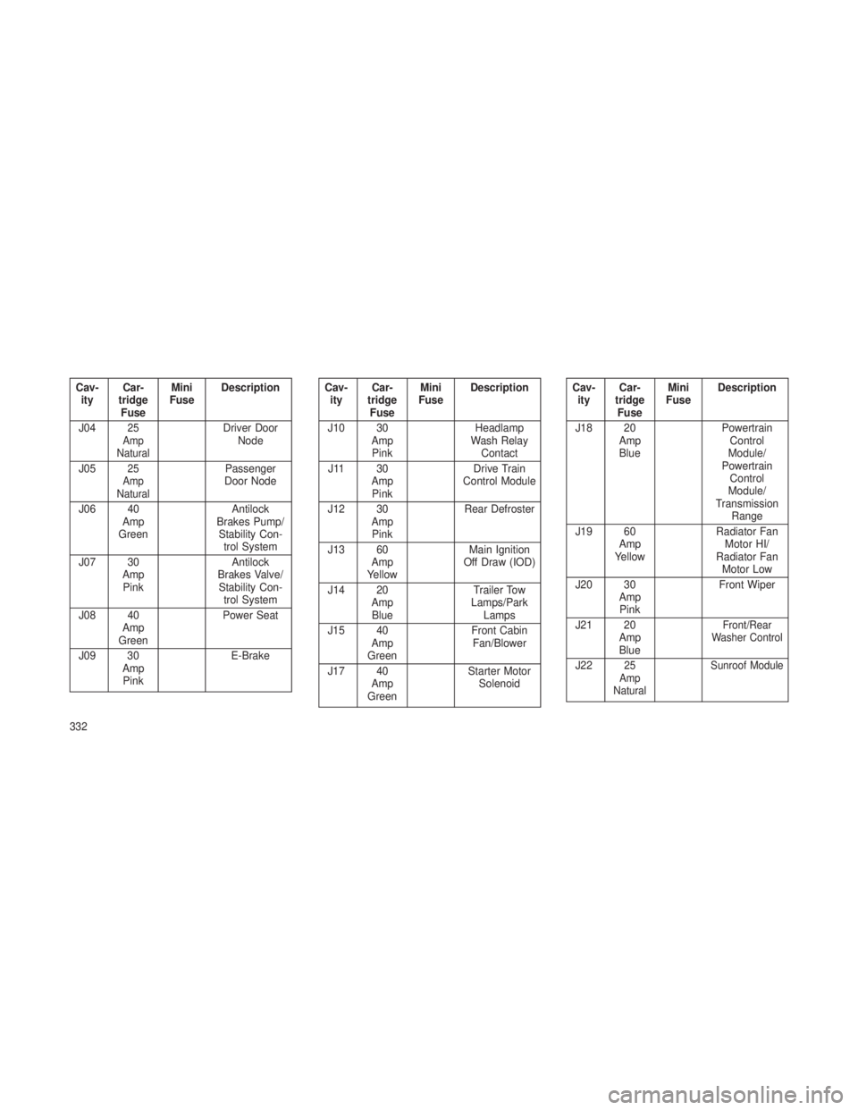
Cav-ity Car-
tridge Fuse Mini
Fuse Description
J04
25
Amp
NaturalDriver Door Node
J05
25
Amp
NaturalPassenger
Door Node
J06 40 Amp
Green Antilock
Brakes Pump/ Stability Con- trol System
J07 30 AmpPink Antilock
Brakes Valve/ Stability Con- trol System
J08 40 Amp
Green Power Seat
J09 30 AmpPink E-Brake
Cav-
ity Car-
tridge Fuse Mini
Fuse Description
J10 30 AmpPink Headlamp
Wash Relay Contact
J11 30 AmpPink Drive Train
Control Module
J12 30 AmpPink Rear Defroster
J13 60 Amp
Yellow Main Ignition
Off Draw (IOD)
J14 20 AmpBlue Trailer Tow
Lamps/Park Lamps
J15 40 Amp
Green Front Cabin
Fan/Blower
J17 40 Amp
Green Starter Motor
SolenoidCav-ity Car-
tridge Fuse Mini
Fuse Description
J18 20 AmpBlue Powertrain
Control
Module/
Powertrain Control
Module/
Transmission Range
J19 60 Amp
Yellow Radiator Fan
Motor HI/
Radiator Fan Motor Low
J20 30 AmpPink Front Wiper
J21 20 AmpBlue
Front/Rear
Washer Control
J2225
Amp
Natural Sunroof Module
332