wheel JEEP GRAND CHEROKEE 2016 WK2 / 4.G Workshop Manual
[x] Cancel search | Manufacturer: JEEP, Model Year: 2016, Model line: GRAND CHEROKEE, Model: JEEP GRAND CHEROKEE 2016 WK2 / 4.GPages: 276, PDF Size: 10.84 MB
Page 203 of 276
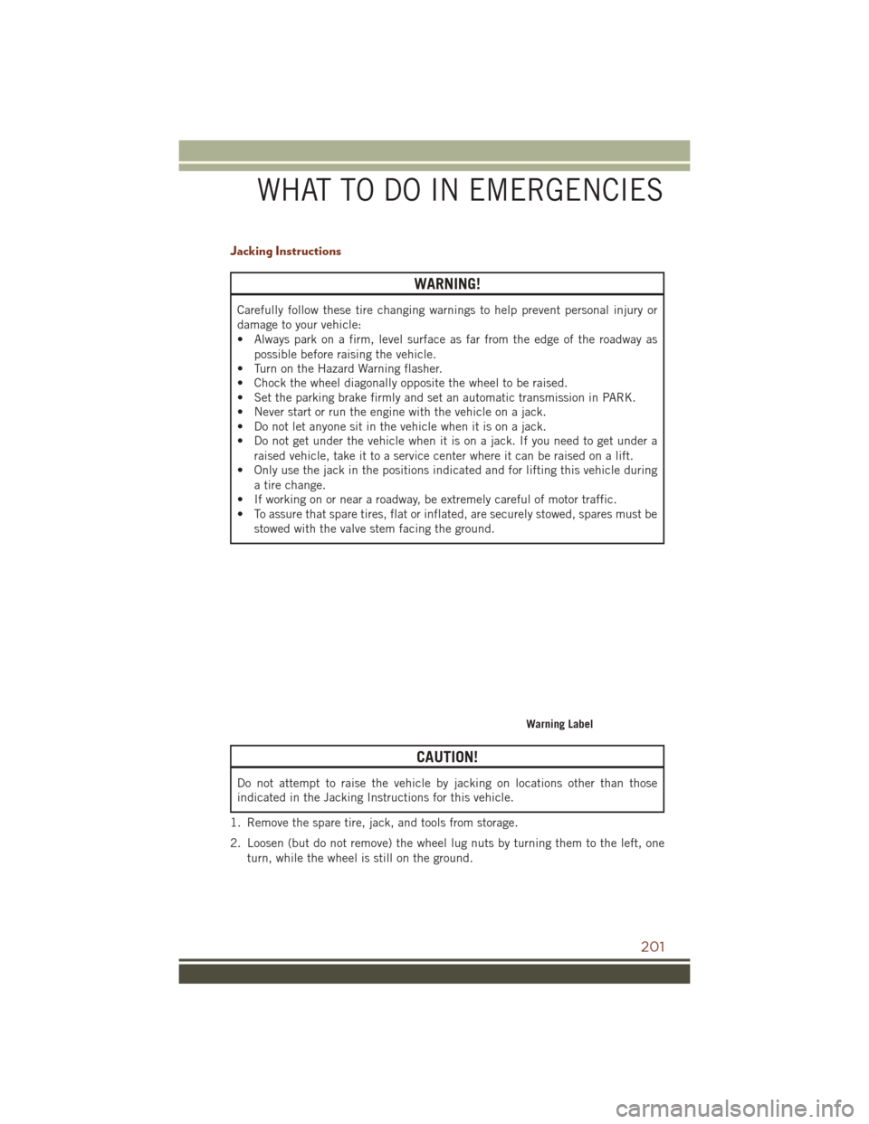
Jacking Instructions
WARNING!
Carefully follow these tire changing warnings to help prevent personal injury or
damage to your vehicle:
• Always park on a firm, level surface as far from the edge of the roadway aspossible before raising the vehicle.
• Turn on the Hazard Warning flasher.
• Chock the wheel diagonally opposite the wheel to be raised.
• Set the parking brake firmly and set an automatic transmission in PARK.
• Never start or run the engine with the vehicle on a jack.
• Do not let anyone sit in the vehicle when it is on a jack.
• Do not get under the vehicle when it is on a jack. If you need to get under a
raised vehicle, take it to a service center where it can be raised on a lift.
• Only use the jack in the positions indicated and for lifting this vehicle during
a tire change.
• If working on or near a roadway, be extremely careful of motor traffic.
• To assure that spare tires, flat or inflated, are securely stowed, spares must be
stowed with the valve stem facing the ground.
CAUTION!
Do not attempt to raise the vehicle by jacking on locations other than those
indicated in the Jacking Instructions for this vehicle.
1. Remove the spare tire, jack, and tools from storage.
2. Loosen (but do not remove) the wheel lug nuts by turning them to the left, one turn, while the wheel is still on the ground.
Warning Label
WHAT TO DO IN EMERGENCIES
201
Page 206 of 276
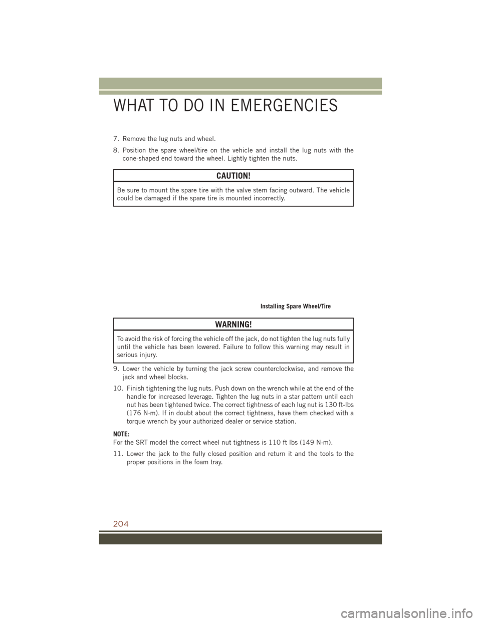
7. Remove the lug nuts and wheel.
8. Position the spare wheel/tire on the vehicle and install the lug nuts with thecone-shaped end toward the wheel. Lightly tighten the nuts.
CAUTION!
Be sure to mount the spare tire with the valve stem facing outward. The vehicle
could be damaged if the spare tire is mounted incorrectly.
WARNING!
To avoid the risk of forcing the vehicle off the jack, do not tighten the lug nuts fully
until the vehicle has been lowered. Failure to follow this warning may result in
serious injury.
9. Lower the vehicle by turning the jack screw counterclockwise, and remove the jack and wheel blocks.
10. Finish tightening the lug nuts. Push down on the wrench while at the end of the handle for increased leverage. Tighten the lug nuts in a star pattern until each
nut has been tightened twice. The correct tightness of each lug nut is 130 ft-lbs
(176 N·m). If in doubt about the correct tightness, have them checked with a
torque wrench by your authorized dealer or service station.
NOTE:
For the SRT model the correct wheel nut tightness is 110 ft lbs (149 N·m).
11. Lower the jack to the fully closed position and return it and the tools to the proper positions in the foam tray.
Installing Spare Wheel/Tire
WHAT TO DO IN EMERGENCIES
204
Page 207 of 276
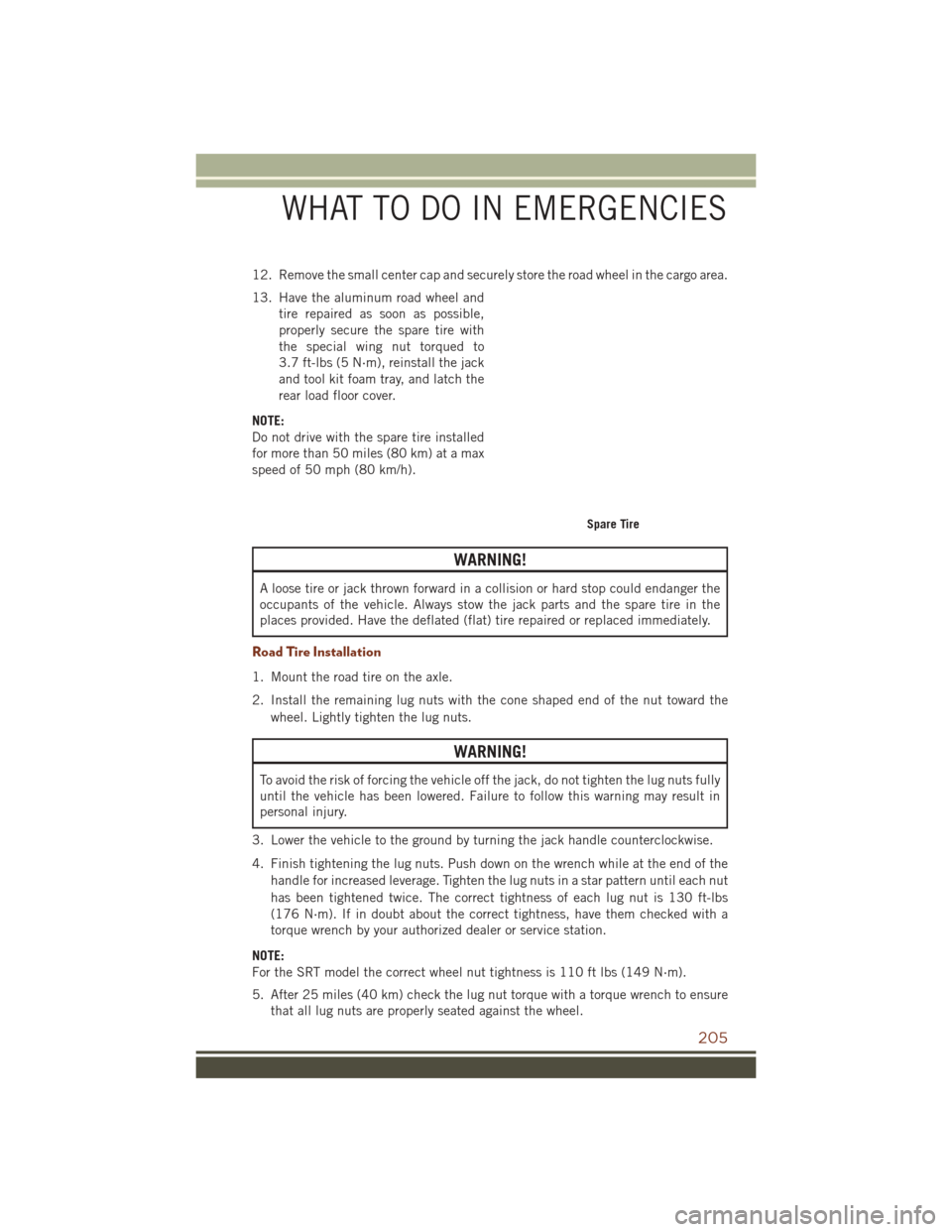
12. Remove the small center cap and securely store the road wheel in the cargo area.
13. Have the aluminum road wheel andtire repaired as soon as possible,
properly secure the spare tire with
the special wing nut torqued to
3.7 ft-lbs (5 N·m), reinstall the jack
and tool kit foam tray, and latch the
rear load floor cover.
NOTE:
Do not drive with the spare tire installed
for more than 50 miles (80 km) at a max
speed of 50 mph (80 km/h).
WARNING!
A loose tire or jack thrown forward in a collision or hard stop could endanger the
occupants of the vehicle. Always stow the jack parts and the spare tire in the
places provided. Have the deflated (flat) tire repaired or replaced immediately.
Road Tire Installation
1. Mount the road tire on the axle.
2. Install the remaining lug nuts with the cone shaped end of the nut toward the wheel. Lightly tighten the lug nuts.
WARNING!
To avoid the risk of forcing the vehicle off the jack, do not tighten the lug nuts fully
until the vehicle has been lowered. Failure to follow this warning may result in
personal injury.
3. Lower the vehicle to the ground by turning the jack handle counterclockwise.
4. Finish tightening the lug nuts. Push down on the wrench while at the end of the handle for increased leverage. Tighten the lug nuts in a star pattern until each nut
has been tightened twice. The correct tightness of each lug nut is 130 ft-lbs
(176 N·m). If in doubt about the correct tightness, have them checked with a
torque wrench by your authorized dealer or service station.
NOTE:
For the SRT model the correct wheel nut tightness is 110 ft lbs (149 N·m).
5. After 25 miles (40 km) check the lug nut torque with a torque wrench to ensure that all lug nuts are properly seated against the wheel.
Spare Tire
WHAT TO DO IN EMERGENCIES
205
Page 214 of 276
TOWING A DISABLED VEHICLE
This section describes procedures for towing a disabled vehicle using a commercial
towing service. If the transmission and drivetrain are operable, disabled vehicles may
also be towed as described under “Recreational Towing” in the “Starting and
Operating” section in the Owners Manual on the DVD.
NOTE:
Vehicles equipped with Quadra-Lift must be placed in Transport mode, before tying
them down (from the body) on a trailer or flatbed truck. Refer to the section on
Quadra-Lift for more information. If the vehicle cannot be placed in Transport mode
(for example, engine will not run), tie-downs must be fastened to the axles (not to the
body). Failure to follow these instructions may cause fault codes to be set and/or
cause loss of proper tie-down tension.
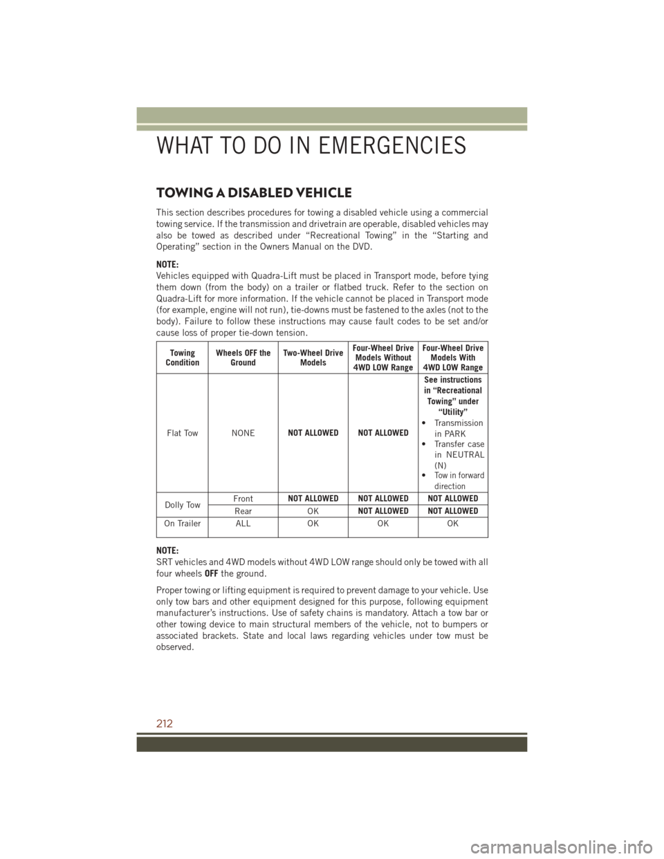
Towing
Condition Wheels OFF the
Ground Two-Wheel Drive
Models Four-Wheel Drive
Models Without
4WD LOW Range Four-Wheel Drive
Models With
4WD LOW Range
Flat Tow NONE NOT ALLOWED NOT ALLOWED See instructions
in “Recreational Towing” under “Utility”
• Transmission
in PARK
• Transfer case
in NEUTRAL
(N)
•
Tow in forward
direction
Dolly Tow Front
NOT ALLOWED NOT ALLOWED NOT ALLOWED
Rear OKNOT ALLOWED NOT ALLOWED
On Trailer ALL OKOKOK
NOTE:
SRT vehicles and 4WD models without 4WD LOW range should only be towed with all
four wheelsOFFthe ground.
Proper towing or lifting equipment is required to prevent damage to your vehicle. Use
only tow bars and other equipment designed for this purpose, following equipment
manufacturer’s instructions. Use of safety chains is mandatory. Attach a tow bar or
other towing device to main structural members of the vehicle, not to bumpers or
associated brackets. State and local laws regarding vehicles under tow must be
observed.
WHAT TO DO IN EMERGENCIES
212
Page 215 of 276
If you must use the accessories (wipers, defrosters, etc.) while being towed, the
ignition must be in the ON/RUN position, not the ACC position.
If the key fob is unavailable, or the vehicle's battery is discharged, refer to “Manual
Park Release” in this section for instructions on shifting the transmission out of
PARK for towing.
CAUTION!
• Do not use sling type equipment when towing. Vehicle damage may occur.
• When securing the vehicle to a flat bed truck, do not attach to front or rearsuspension components. Damage to your vehicle may result from improper
towing.
Two-Wheel Drive Models
The manufacturer recommends towing your vehicle with all four wheels OFFthe
ground using a flatbed.
If flatbed equipment is not available, and the transmission is operable, the vehicle
may be towed (with rear wheels on the ground) under the following conditions:
• The transmission must be in NEUTRAL. Refer to "Manual Park Release" in this section for instructions on shifting the transmission to NEUTRAL when the engine
is off.
• The towing speed must not exceed 30 mph (48 km/h).
• The towing distance must not exceed 30 miles (48 km).
If the transmission is not operable, or the vehicle must be towed faster than 30 mph
(48 km/h) or farther than 30 miles (48 km), tow with the rear wheels OFFthe ground.
Acceptable methods are to tow the vehicle on a flatbed, or with the front wheels
raised and the rear wheels on a towing dolly, or (when using a suitable steering wheel
stabilizer to hold the front wheels in the straight position) with the rear wheels raised
and the front wheels on the ground.
CAUTION!
Towing faster than 30 mph (48 km/h) or farther than 30 miles (48 km) with rear
wheels on the ground can cause severe transmission damage. Damage from
improper towing is not covered under the New Vehicle Limited Warranty.
WHAT TO DO IN EMERGENCIES
213
Page 216 of 276
Four-Wheel Drive Models
The manufacturer recommends towing with all wheelsOFFthe ground. Acceptable
methods are to tow the vehicle on a flatbed or with one end of vehicle raised and the
opposite end on a towing dolly.
If flatbed equipment is not available, and the transfer case is operable, vehicles with
a two-speed transfer case may be towed (in the forward direction, with ALLwheels on
the ground), IFthe transfer case is in NEUTRAL (N) and the transmission is in PARK.
Refer to “Recreational Towing” in “Starting And Operating” in the Owner’s Manual
on the DVD for detailed instructions.
Vehicles equipped with a single-speed transfer case have no NEUTRAL position, and
therefore mustbe towed with all four wheels OFFthe ground.
CAUTION!
• Front or rear wheel lifts must not be used. Internal damage to the transmission
or transfer case will occur if a front or rear wheel lift is used when towing.
• Towing this vehicle in violation of the above requirements can cause severe
transmission and/or transfer case damage. Damage from improper towing is
not covered under the New Vehicle Limited Warranty.
FREEING A STUCK VEHICLE
If your vehicle becomes stuck in mud, sand or snow, it can often be moved using a
rocking motion. Turn the steering wheel right and left to clear the area around the
front wheels. Push and hold the lock button on the gear selector. Then shift back and
forth between DRIVE and REVERSE while gently pressing the accelerator.
NOTE:
Shifts between DRIVE and REVERSE can only be achieved at wheel speeds of 5 mph
(8 km/h) or less. Whenever the transmission remains in NEUTRAL for more than two
seconds, you must push the brake pedal to engage DRIVE or REVERSE.
Use the least amount of accelerator pedal pressure that will maintain the rocking
motion without spinning the wheels or racing the engine.
WHAT TO DO IN EMERGENCIES
214
Page 217 of 276
NOTE:
Push the "ESC Off" switch (if necessary), to place the Electronic Stability Control
(ESC) system in "Partial Off" mode, before rocking the vehicle. Refer to “Electronic
Brake Control” in “Starting And Operating” in the Owners Manual on the DVD for
further information. Once the vehicle has been freed, push the "ESC Off" switch
again to restore "ESC On" mode.
CAUTION!
Racing the engine or spinning the wheels may lead to transmission overheating
and failure. Allow the engine to idle with the transmission in NEUTRAL for at least
one minute after every five rocking-motion cycles. This will minimize overheating
and reduce the risk of transmission failure during prolonged efforts to free a stuck
vehicle.
WARNING!
Fast spinning tires can be dangerous. Forces generated by excessive wheel speeds
may cause damage, or even failure, of the axle and tires. A tire could explode and
injure someone. Do not spin your vehicle's wheels faster than 30 mph (48 km/h)
or for longer than 30 seconds continuously without stopping when you are stuck
and do not let anyone near a spinning wheel, no matter what the speed.
CAUTION!
• When “rocking” a stuck vehicle by shifting between DRIVE and REVERSE, donot spin the wheels faster than 15 mph (24 km/h), or drivetrain damage may
result.
• Revving the engine or spinning the wheels too fast may lead to transmission
overheating and failure. It can also damage the tires. Do not spin the wheels
above 30 mph (48 km/h) while in gear (no transmission shifting occurring).
WHAT TO DO IN EMERGENCIES
215
Page 219 of 276
OPENING THE HOOD
1. Pull the hood release lever locatedbelow the steering wheel at the base
of the instrument panel.
2. Reach into the opening beneath the center of the hood and move the
safety latch lever while lifting the
hood at the same time.
WARNING!
Be sure the hood is fully latched before driving your vehicle. If the hood is not fully
latched, it could open when the vehicle is in motion and block your vision. Failure
to follow this warning could result in serious injury or death.
Hood Release Lever
MAINTAINING YOUR VEHICLE
217
Page 241 of 276
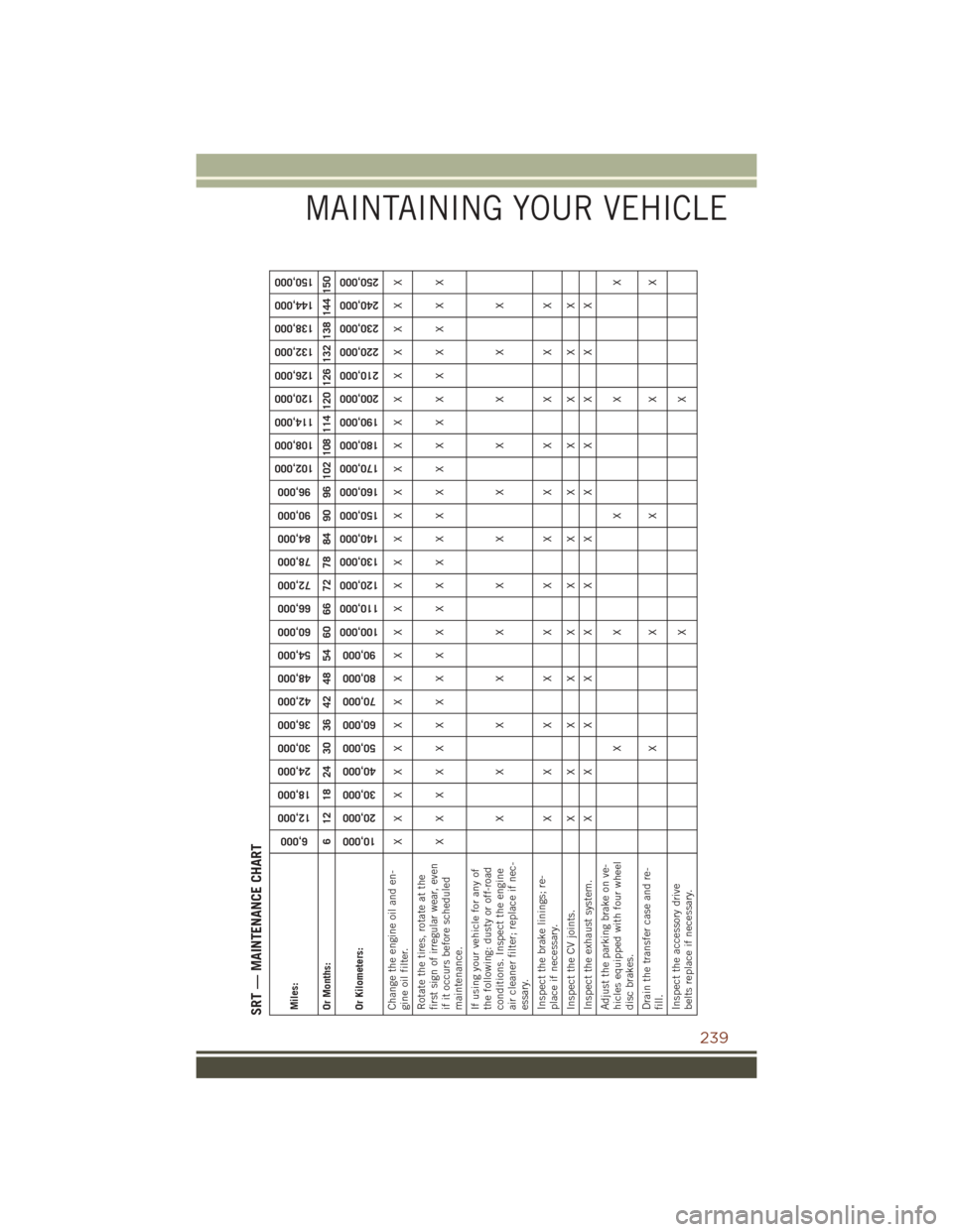
SRT — MAINTENANCE CHARTMiles:
6,000
12,000
18,000
24,000
30,000
36,000
42,000
48,000
54,000
60,000
66,000
72,000
78,000
84,000
90,000
96,000
102,000
108,000
114,000
120,000
126,000
132,000
138,000
144,000
150,000
Or Months: 6 12 18 24 30 36 42 48 54 60 66 72 78 84 90 96 102 108 114 120 126 132 138 144 150
Or Kilometers:
10,000
20,000
30,000
40,000
50,000
60,000
70,000
80,000
90,000
100,000
110,000
120,000
130,000
140,000
150,000
160,000
170,000
180,000
190,000
200,000
210,000
220,000
230,000
240,000
250,000
Change the engine oil and en-
gine oil filter. XXXXXXXXXXXXXXXXXXXXXXXXX
Rotate the tires, rotate at the
first sign of irregular wear, even
if it occurs before scheduled
maintenance. XXXXXXXXXXXXXXXXXXXXXXXXX
If using your vehicle for any of
the following: dusty or off-road
conditions. Inspect the engine
air cleaner filter; replace if nec-
essary. XXXXXXXXXXXX
Inspect the brake linings; re-
place if necessary. XXXXXXXXXXXX
Inspect the CV joints. X X X X X X X X X X X X
Inspect the exhaust system. X X X X X X X X X X X X
Adjust the parking brake on ve-
hicles equipped with four wheel
disc brakes. XXXXX
Drain the transfer case and re-
fill. XXXXX
Inspect the accessory drive
belts replace if necessary. XX
MAINTAINING YOUR VEHICLE
239
Page 253 of 276
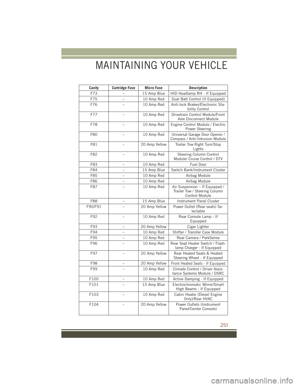
Cavity Cartridge Fuse Micro FuseDescription
F73 – 15 Amp Blue HID Headlamp RH - If Equipped
F75 – 10 Amp Red Dual Batt Control (If Equipped)
F76 – 10 Amp Red Anti-lock Brakes/Electronic Sta-
bility Control
F77 – 10 Amp Red Drivetrain Control Module/Front
Axle Disconnect Module
F78 – 10 Amp Red Engine Control Module / Electric
Power Steering
F80 – 10 Amp Red Universal Garage Door Opener /
Compass / Anti-Intrusion Module
F81 – 20 Amp Yellow Trailer Tow Right Turn/Stop
Lights
F82 – 10 Amp Red Steering Column Control
Module/ Cruise Control / DTV
F83 – 10 Amp Red Fuel Door
F84 – 15 Amp Blue Switch Bank/Instrument Cluster
F85 – 10 Amp Red Airbag Module
F86 – 10 Amp Red Airbag Module
F87 – 10 Amp Red Air Suspension – If Equipped /
Trailer Tow / Steering ColumnControl Module
F88 – 15 Amp Blue Instrument Panel Cluster
F90/F91 – 20 Amp Yellow Power Outlet (Rear seats) Se-
lectable
F92 – 10 Amp Red Rear Console Lamp - If
Equipped
F93 – 20 Amp Yellow Cigar Lighter
F94 – 10 Amp Red Shifter / Transfer Case Module
F95 – 10 Amp Red Rear Camera / ParkSense
F96 – 10 Amp Red Rear Seat Heater Switch / Flash-
lamp Charger - If Equipped
F97 – 20 Amp Yellow Rear Heated Seats & Heated
Steering Wheel - If Equipped
F98 – 20 Amp Yellow
Front Heated Seats - If Equipped
F99– 10 Amp Red Climate Control / Driver Assis-
tance Systems Module / DSRC
F100 – 10 Amp Red Active Damping - If Equipped
F101 – 15 Amp Blue Electrochromatic Mirror/Smart
High Beams - If Equipped
F103 – 10 Amp Red Cabin Heater (Diesel Engine
Only)/Rear HVAC
F104 – 20 Amp Yellow Power Outlets (Instrument
Panel/Center Console)
MAINTAINING YOUR VEHICLE
251