suspension JEEP GRAND CHEROKEE 2017 WK2 / 4.G Owner's Manual
[x] Cancel search | Manufacturer: JEEP, Model Year: 2017, Model line: GRAND CHEROKEE, Model: JEEP GRAND CHEROKEE 2017 WK2 / 4.GPages: 372
Page 174 of 372
ing, Suspension, all-wheel drive set up, and
Paddle shifter settings may be configured
through the custom mode set-up.
NOTE:
Refer to “Drive Modes” in the “Multimedia”
section in your Owner’s Manual at
www.jeep.com/en/owners/manuals/ for fur-
ther information.
Active Damping System
This vehicle is equipped with an electronic
controlled damping system. This system re-
duces body roll and pitch in many driving
situations including cornering, acceleration
and braking. There are 3 modes:
•Street Mode (Available in terrain positions
AUTO, SNOW and CUSTOM.) — Used
during highway speeds where a touring
suspension feel is desired.
• Sport Mode (Available in terrain positions
AUTO, SPORT, CUSTOM and TOW.) —
Provides a firm suspension for better han-
dling. •
Track Firm (Available in terrain positions
AUTO, TRACK and CUSTOM.) — Provides
a full firm suspension for an aggressive
track experience.
Refer to “Drive Modes” in the “Multimedia”
section in your Owner’s Manual at
www.jeep.com/en/owners/manuals/ for fur-
ther information.
ELECTRONIC SPEED
CONTROL
When engaged, the Electronic Speed Control
takes over accelerator operations at speeds
greater than 25 mph (40 km/h).
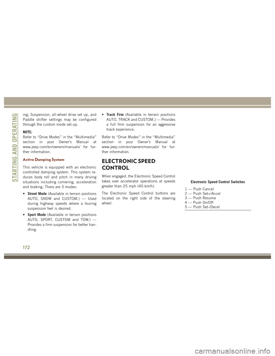
The Electronic Speed Control buttons are
located on the right side of the steering
wheel.
Electronic Speed Control Switches
1 — Push Cancel
2 — Push Set+/Accel
3 — Push Resume
4 — Push On/Off
5 — Push Set-/Decel
STARTING AND OPERATING
172
Page 201 of 372
Recreational Towing-Two Wheel Drive
Models
DO NOT flat tow this vehicle. Damage to the
drivetrain will result.
Recreational towing (for two-wheel drive
models) is allowed ONLY if the rear wheels
are OFF the ground. This may be accom-
plished using a tow dolly or vehicle trailer. If
using a tow dolly, follow this procedure:
1. Properly secure the dolly to the tow ve-hicle, following the dolly manufacturer's
instructions.
NOTE:
If vehicle is equipped with Quadra-Lift air
suspension, ensure the vehicle is set to
Normal Ride Height.
2. Drive the rear wheels onto the tow dolly.
3. Firmly apply the parking brake. Shift the transmission into PARK.
4. Turn the ignition OFF.
5. Properly secure the rear wheels to the dolly, following the dolly manufacturer’s
instructions. 6. Install a suitable clamping device, de-
signed for towing, to secure the front
wheels in the straight position.
CAUTION!
Towing with the rear wheels on the ground
will cause severe transmission damage.
Damage from improper towing is not cov-
ered under the New Vehicle Limited War-
ranty.
Recreational Towing — Quadra-Trac I
(Single-Speed Transfer Case) Four-Wheel
Drive Models
Recreational towing is not allowed. These
models do not have a NEUTRAL (N) position
in the transfer case.
NOTE:
This vehicle may be towed on a flatbed or
vehicle trailer provided all four wheels are OFF
the ground.
CAUTION!
Towing this vehicle in violation of the
above requirements can cause severe
transmission and/or transfer case damage.
Damage from improper towing is not cov-
ered under the New Vehicle Limited War-
ranty.
Recreational Towing — Quadra–Trac
II/Quadra–Drive II Four-Wheel Drive
Models
The transfer case must be shifted into NEU-
TRAL (N) and the transmission must be in
PARK for recreational towing. The NEUTRAL
(N) selection button is adjacent to the trans-
fer case selector switch. Shifts into and out of
transfer case NEUTRAL (N) can take place
with the selector switch in any mode position.
CAUTION!
• DO NOT dolly tow any 4WD vehicle. Towing with only one set of wheels on the
ground (front or rear) will cause severe
transmission and/or transfer case dam-
199
Page 202 of 372
CAUTION!
age. Tow with all four wheels either ON
the ground, or OFF the ground (using a
vehicle trailer).
• Tow only in a forward direction. Towing
this vehicle backwards can cause severe
damage to the transfer case.
• The transmission must be in PARK for
recreational towing.
• Before recreational towing, perform the
procedure outlined under “Shifting into
NEUTRAL (N)” to be certain that the
transfer case is fully in NEUTRAL (N).
Otherwise, internal damage will result.
• Towing this vehicle in violation of the
above requirements can cause severe
transmission and/or transfer case dam-
age. Damage from improper towing is
not covered under the New Vehicle Lim-
ited Warranty.
• Do not use a bumper-mounted clamp-on
tow bar on your vehicle. The bumper
face bar will be damaged.
Shifting Into NEUTRAL (N)
WARNING!
You or others could be injured or killed if
you leave the vehicle unattended with the
transfer case in the NEUTRAL (N) position
without first fully engaging the parking
brake. The transfer case NEUTRAL (N)
position disengages both the front and rear
driveshafts from the powertrain and will
allow the vehicle to roll, even if the trans-
mission is in PARK. The parking brake
should always be applied when the driver
is not in the vehicle.
Use the following procedure to prepare your
vehicle for recreational towing.
CAUTION!
It is necessary to follow these steps to be
certain that the transfer case is fully in
NEUTRAL (N) before recreational towing
to prevent damage to internal parts. 1. Bring the vehicle to a complete stop, with
the engine running.
2. Press and hold the brake pedal.
3. Shift the transmission into NEUTRAL.
4. If vehicle is equipped with Quadra-Lift air suspension, ensure the vehicle is set to
Normal Ride Height.
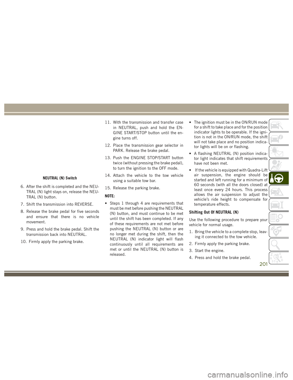
5. Using a ballpoint pen or similar object, push and hold the recessed transfer case
NEUTRAL (N) button (located by the se-
lector switch) for four seconds. The light
behind the N symbol will blink, indicating
shift in progress. The light will stop blink-
ing (stay on solid) when the shift to NEU-
TRAL (N) is complete. A “FOUR WHEEL
DRIVE SYSTEM IN NEUTRAL” message
will appear in the instrument cluster.
STARTING AND OPERATING
200
Page 203 of 372
6. After the shift is completed and the NEU-TRAL (N) light stays on, release the NEU-
TRAL (N) button.
7. Shift the transmission into REVERSE.
8. Release the brake pedal for five seconds and ensure that there is no vehicle
movement.
9. Press and hold the brake pedal. Shift the transmission back into NEUTRAL.
10. Firmly apply the parking brake. 11. With the transmission and transfer case
in NEUTRAL, push and hold the EN-
GINE START/STOP button until the en-
gine turns off.
12. Place the transmission gear selector in PARK. Release the brake pedal.
13. Push the ENGINE STOP/START button twice (without pressing the brake pedal),
to turn the ignition to the OFF mode.
14. Attach the vehicle to the tow vehicle using a suitable tow bar.
15. Release the parking brake.
NOTE:
• Steps 1 through 4 are requirements that must be met before pushing the NEUTRAL
(N) button, and must continue to be met
until the shift has been completed. If any
of these requirements are not met before
pushing the NEUTRAL (N) button or are
no longer met during the shift, then the
NEUTRAL (N) indicator light will flash
continuously until all requirements are
met or until the NEUTRAL (N) button is
released. • The ignition must be in the ON/RUN mode
for a shift to take place and for the position
indicator lights to be operable. If the igni-
tion is not in the ON/RUN mode, the shift
will not take place and no position indica-
tor lights will be on or flashing.
• A flashing NEUTRAL (N) position indica- tor light indicates that shift requirements
have not been met.
• If the vehicle is equipped with Quadra-Lift air suspension, the engine should be
started and left running for a minimum of
60 seconds (with all the doors closed) at
least once every 24 hours. This process
allows the air suspension to adjust the
vehicle’s ride height to compensate for
temperature effects.
Shifting Out Of NEUTRAL (N)
Use the following procedure to prepare your
vehicle for normal usage.
1. Bring the vehicle to a complete stop, leav-
ing it connected to the tow vehicle.
2. Firmly apply the parking brake.
3. Start the engine.
4. Press and hold the brake pedal.
NEUTRAL (N) Switch
201
Page 212 of 372
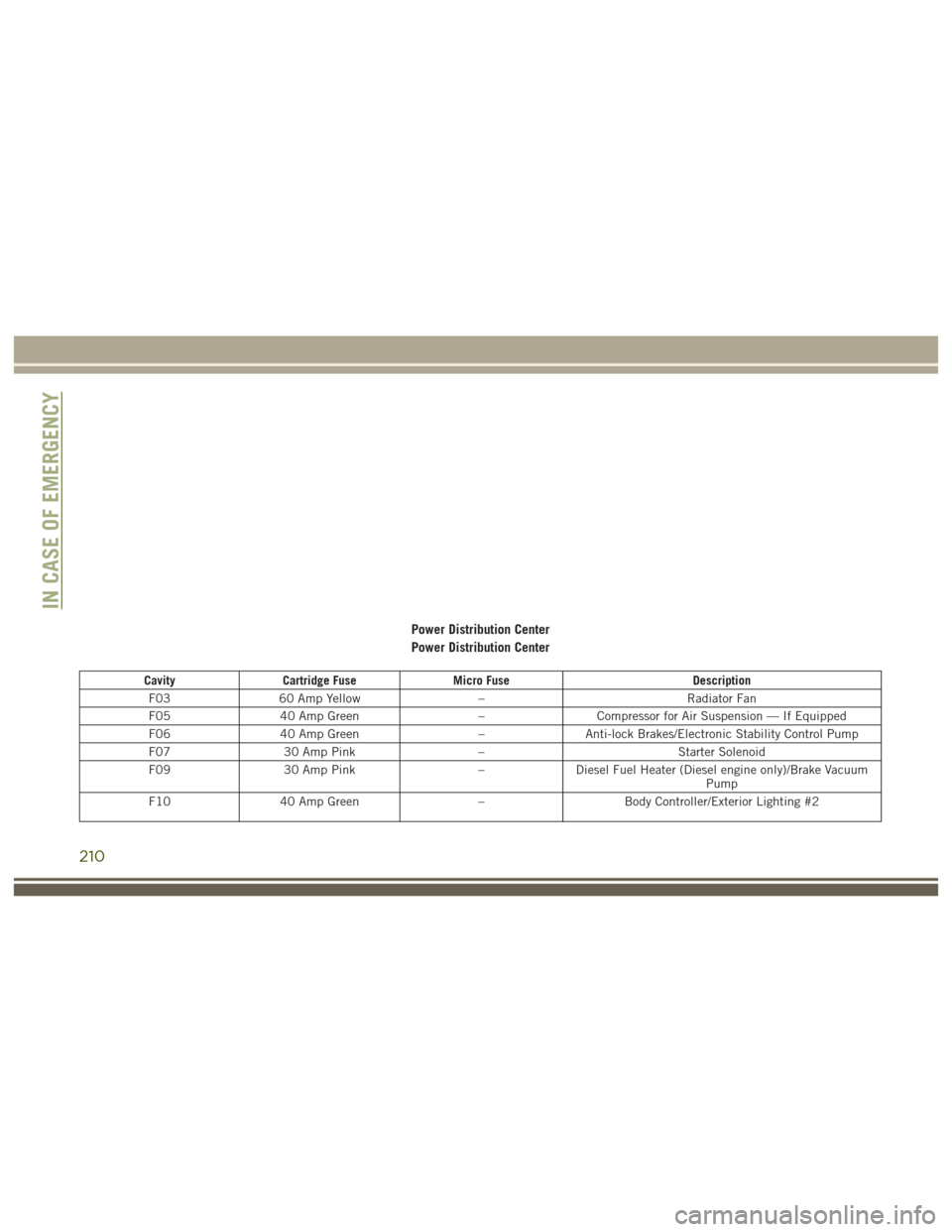
CavityCartridge Fuse Micro Fuse Description
F03 60 Amp Yellow – Radiator Fan
F05 40 Amp Green –Compressor for Air Suspension — If Equipped
F06 40 Amp Green –Anti-lock Brakes/Electronic Stability Control Pump
F07 30 Amp Pink – Starter Solenoid
F09 30 Amp Pink –Diesel Fuel Heater (Diesel engine only)/Brake Vacuum
Pump
F10 40 Amp Green –Body Controller/Exterior Lighting #2
Power Distribution Center
Power Distribution Center
IN CASE OF EMERGENCY
210
Page 214 of 372
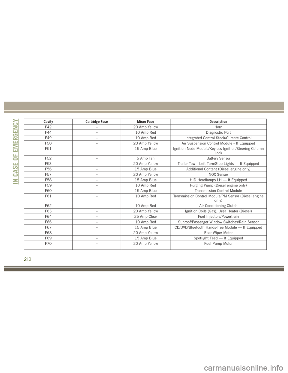
CavityCartridge Fuse Micro Fuse Description
F42 –20 Amp Yellow Horn
F44 –10 Amp Red Diagnostic Port
F49 –10 Amp Red Integrated Central Stack/Climate Control
F50 –20 Amp Yellow Air Suspension Control Module - If Equipped
F51 –15 Amp Blue Ignition Node Module/Keyless Ignition/Steering Column
Lock
F52 –5 Amp Tan Battery Sensor
F53 –20 Amp Yellow Trailer Tow – Left Turn/Stop Lights — If Equipped
F56 –15 Amp Blue Additional Content (Diesel engine only)
F57 –20 Amp Yellow NOX Sensor
F58 –15 Amp Blue HID Headlamps LH — If Equipped
F59 –10 Amp Red Purging Pump (Diesel engine only)
F60 –15 Amp Blue Transmission Control Module
F61 –10 Amp Red Transmission Control Module/PM Sensor (Diesel engine
only)
F62 –10 Amp Red Air Conditioning Clutch
F63 –20 Amp Yellow Ignition Coils (Gas), Urea Heater (Diesel)
F64 –25 Amp Clear Fuel Injectors/Powertrain
F66 –10 Amp Red Sunroof/Passenger Window Switches/Rain Sensor
F67 –15 Amp Blue CD/DVD/Bluetooth Hands-free Module — If Equipped
F68 –20 Amp Yellow Rear Wiper Motor
F69 –15 Amp Blue Spotlight Feed — If Equipped
F70 –20 Amp Yellow Fuel Pump Motor
IN CASE OF EMERGENCY
212
Page 215 of 372
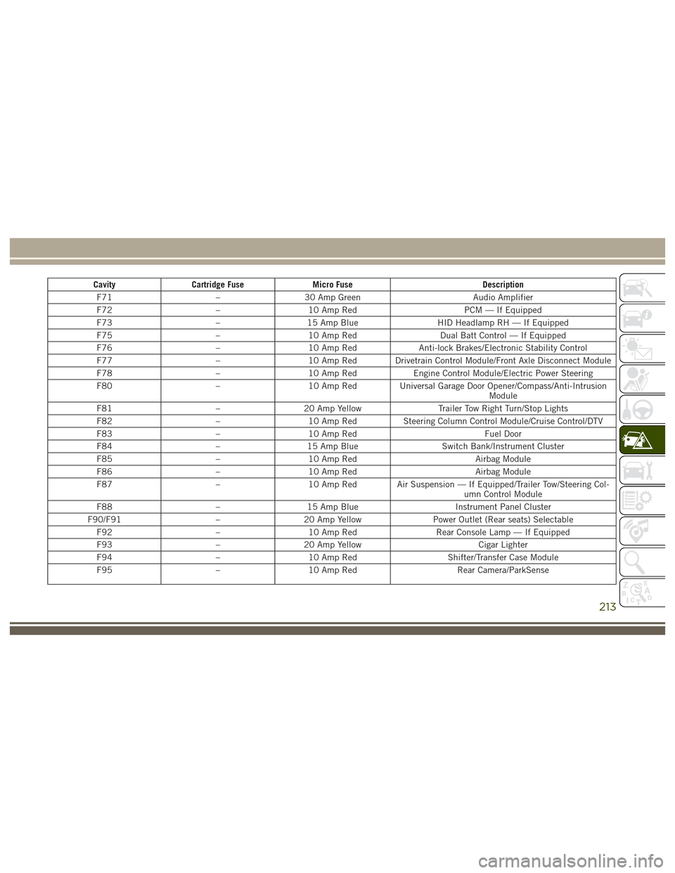
CavityCartridge Fuse Micro Fuse Description
F71 –30 Amp Green Audio Amplifier
F72 –10 Amp Red PCM — If Equipped
F73 –15 Amp Blue HID Headlamp RH — If Equipped
F75 –10 Amp Red Dual Batt Control — If Equipped
F76 –10 Amp Red Anti-lock Brakes/Electronic Stability Control
F77 –10 Amp Red Drivetrain Control Module/Front Axle Disconnect Module
F78 –10 Amp Red Engine Control Module/Electric Power Steering
F80 –10 Amp Red Universal Garage Door Opener/Compass/Anti-Intrusion
Module
F81 –20 Amp Yellow Trailer Tow Right Turn/Stop Lights
F82 –10 Amp Red Steering Column Control Module/Cruise Control/DTV
F83 –10 Amp Red Fuel Door
F84 –15 Amp Blue Switch Bank/Instrument Cluster
F85 –10 Amp Red Airbag Module
F86 –10 Amp Red Airbag Module
F87 –10 Amp Red Air Suspension — If Equipped/Trailer Tow/Steering Col-
umn Control Module
F88 –15 Amp Blue Instrument Panel Cluster
F90/F91 –20 Amp Yellow Power Outlet (Rear seats) Selectable
F92 –10 Amp Red Rear Console Lamp — If Equipped
F93 –20 Amp Yellow Cigar Lighter
F94 –10 Amp Red Shifter/Transfer Case Module
F95 –10 Amp Red Rear Camera/ParkSense
213
Page 217 of 372
WARNING!
Do not exceed 50 mph (80 km/h) if the
“Tire Pressure Monitoring Telltale Light” is
illuminated. Vehicle handling and braking
may be reduced. You could have a collision
and be severely or fatally injured.
Jack/Spare Tire Stowage
Jack Location
The scissor-type jack and tire changing tools
are located in rear cargo area, below the load
floor.Spare Tire Stowage
The spare tire is stowed under the load floor
in the rear cargo area and is secured to the
body with a special wing nut.
Preparations For Jacking
CAUTION!
Always lift or jack the vehicle from the
correct jacking points. Failure to follow
this information could cause damage to
the vehicle or underbody components.
NOTE:
To assist with changing a spare tire, the air
suspension system (if equipped) has a fea-
ture which allows the automatic leveling to be
disabled.
1. Park the vehicle on a firm, level surface. Avoid ice or slippery surfaces.
Spare Tire/Jack And Tools
1 — Cap-Less Fuel Fill Funnel
2 — Spare Tire
3 — Tire Changing Tools And Jack
215
Page 230 of 372
NOTE:
SRT vehicles and 4WD models without 4WD
LOW range should only be towed with all four
wheelsOFFthe ground.
Proper towing or lifting equipment is required
to prevent damage to your vehicle. Use only
tow bars and other equipment designed for
this purpose, following equipment manufac-
turer’s instructions. Use of safety chains is
mandatory. Attach a tow bar or other towing
device to main structural members of the
vehicle, not to bumpers or associated brack-
ets. State and local laws regarding vehicles
under tow must be observed.
If you must use the accessories (wipers, de-
frosters, etc.) while being towed, the ignition
must be in the ON/RUN mode, not the ACC
mode.
If the key fob is unavailable, or the vehicle's
battery is discharged, refer to “Manual Park
Release” in this section for instructions on
shifting the transmission out of PARK for
towing.CAUTION!
• Do not use sling type equipment when towing. Vehicle damage may occur.
• When securing the vehicle to a flat bed
truck, do not attach to front or rear
suspension components. Damage to
your vehicle may result from improper
towing.
Two-Wheel Drive Models
The manufacturer recommends towing your
vehicle with all four wheels OFFthe ground
using a flatbed.
If flatbed equipment is not available, and the
transmission is operable, the vehicle may be
towed (with rear wheels on the ground) under
the following conditions:
• The transmission must be in NEUTRAL. Refer to "Manual Park Release" in this
section for instructions on shifting the
transmission to NEUTRAL when the en-
gine is off.
• The towing speed must not exceed 30 mph (48 km/h). • The towing distance must not exceed
30 miles (48 km).
If the transmission is not operable, or the
vehicle must be towed faster than 30 mph
(48 km/h) or farther than 30 miles (48 km),
tow with the rear wheels OFFthe ground.
Acceptable methods are to tow the vehicle on
a flatbed, or with the front wheels raised and
the rear wheels on a towing dolly, or (when
using a suitable steering wheel stabilizer to
hold the front wheels in the straight position)
with the rear wheels raised and the front
wheels on the ground.
CAUTION!
Towing faster than 30 mph (48 km/h) or
farther than 30 miles (48 km) with rear
wheels on the ground can cause severe
transmission damage. Damage from im-
proper towing is not covered under the
New Vehicle Limited Warranty.
IN CASE OF EMERGENCY
228
Page 235 of 372
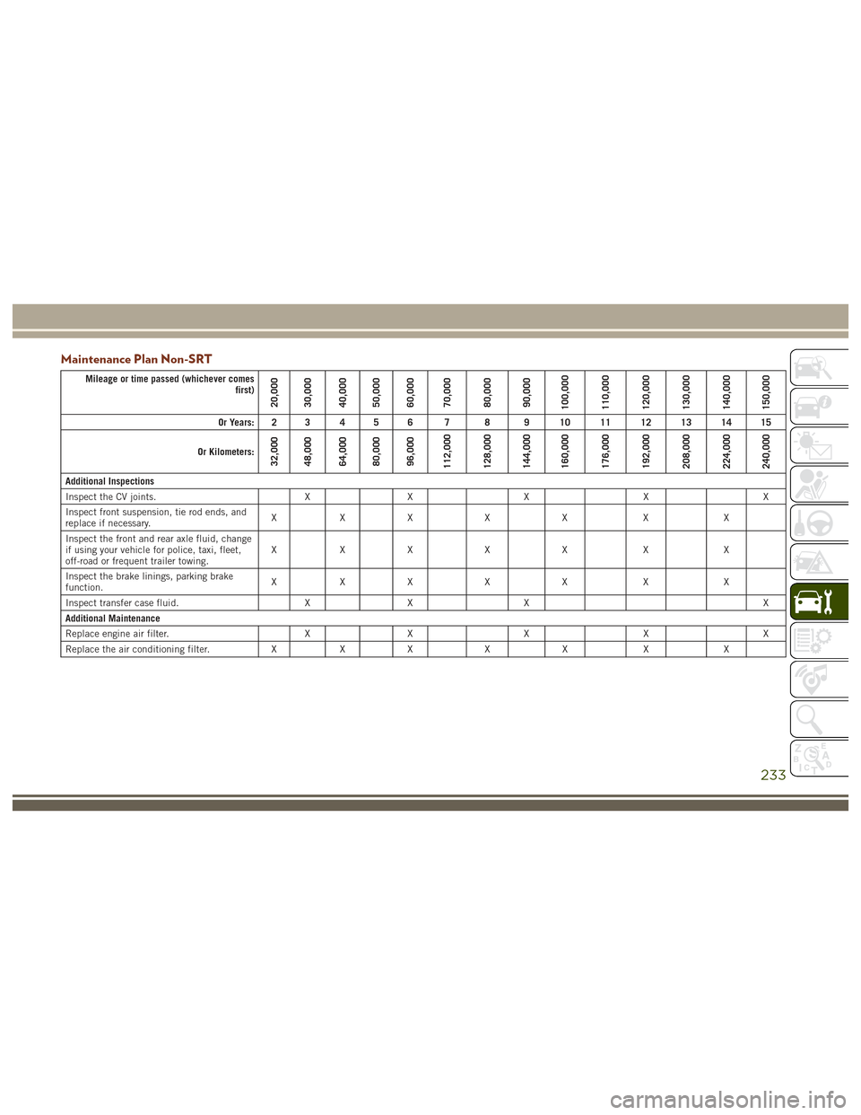
Maintenance Plan Non-SRT
Mileage or time passed (whichever comesfirst)
20,000
30,000
40,000
50,000
60,000
70,000
80,000
90,000
100,000
110,000
120,000
130,000
140,000
150,000
Or Years: 2 3 4 5 6 7 8 9 10 11 12 13 14 15
Or Kilometers:
32,000
48,000
64,000
80,000
96,000
112,000
128,000
144,000
160,000
176,000
192,000
208,000
224,000
240,000
Additional Inspections
Inspect the CV joints. X X X X X
Inspect front suspension, tie rod ends, and
replace if necessary. XXX X X X X
Inspect the front and rear axle fluid, change
if using your vehicle for police, taxi, fleet,
off-road or frequent trailer towing. XXX X X X X
Inspect the brake linings, parking brake
function. XXX X X X X
Inspect transfer case fluid. X X X X
Additional Maintenance
Replace engine air filter. X X X X X
Replace the air conditioning filter. X X X X X X X
233