change wheel JEEP GRAND CHEROKEE 2020 Owner handbook (in English)
[x] Cancel search | Manufacturer: JEEP, Model Year: 2020, Model line: GRAND CHEROKEE, Model: JEEP GRAND CHEROKEE 2020Pages: 378, PDF Size: 6.88 MB
Page 170 of 378
launches, to minimize wheel slippage. If
equipped with air suspension, the default
ride height for Snow is Normal Ride Height
(NRH).
•Auto– Fully automatic full time four-wheel
drive operation can be used on and off road.
Balances traction with seamless steering
feel to provide improved handling and ac-
celeration over two-wheel drive vehicles. If
equipped with air suspension, the level will
change to Normal Ride Height (NRH).
•Sand– Off road calibration for use on low
traction surfaces such as sand or wet grass.
Driveline is maximized for traction. Some
binding may be felt on less forgiving sur-
faces. The electronic brake controls are set
to limit traction control management of
throttle and wheel spin. If equipped with
air suspension, the default ride height for
Sand is Normal Ride Height (NRH).
•Mud– Off road calibration for use on low
traction surfaces such as mud. Driveline is
maximized for traction. Some binding may
be felt on less forgiving surfaces. The elec-
tronic brake controls are set to limit trac-tion control management of throttle and
wheel spin. If equipped with air suspen-
sion, the level will change to Off Road 1.
•Rock– Off road calibration only available in
4WD Low range. The vehicle is raised (if
equipped with Air Suspension) for im-
proved ground clearance. Traction based
tuning with improved steer-ability for use
on high traction off-road surfaces. Use for
low speed obstacles such as large rocks,
deep ruts, etc. If equipped with air suspen-
sion, the vehicle level will change to Off-
Road 2. If the Selec-Terrain switch is in
ROCK mode, and the transfer case is
switched from 4WD Low to 4WD High, the
Selec-Terrain system will return to AUTO.
NOTE:
Activate the Hill Descent Control or Selec
Speed Control for steep downhill control. See
“Electronic Brake Control System” in this
section for further information.Instrument Cluster Display Messages
When the appropriate conditions exist, a
message will appear in the instrument clus-
ter. Refer to “Instrument Cluster Display” in
“Getting To Know Your Instrument Panel” for
further information.
SELEC-TRACK — IF
EQUIPPED (SRT)
Description
Selec-Track combines the capabilities of the
vehicle control systems, along with driver
input, to provide the best performance for all
terrains.
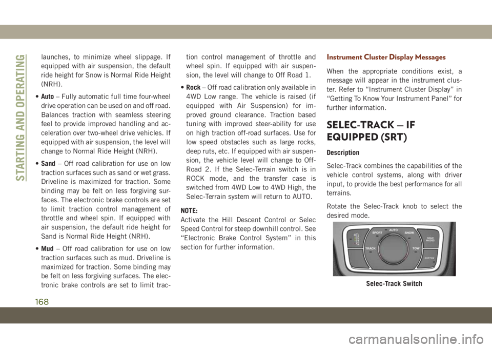
Rotate the Selec-Track knob to select the
desired mode.
Selec-Track Switch
STARTING AND OPERATING
168
Page 173 of 378
Launch control will be active until the vehicle
reaches 62 mph (100 km/h), at which point
the Electronic Stability Control (ESC) system
will return to its current ESC mode.
Launch control will abort before launch
completion, display “Launch Aborted” in the
cluster under any the following conditions:
• The accelerator pedal is released during
launch.
• The ESC system detects that the vehicle is
no longer moving in a straight line.
• The “ESC OFF” button is pressed to change
the system to another mode.
NOTE:
After launch control has been aborted, ESC
will return to its current ESC mode.
CAUTION!
Do not attempt to shift when the drive
wheels are spinning and do not have trac-
tion. Damage to the transmission may oc-
cur.
Guidelines For Track Use
NOTE:
Because of the extreme conditions encoun-
tered during track use, any damage or wear
associated with track use may not be covered
by warranty.
• If your SRT vehicle is equipped with Drive
Modes they will alter the vehicle’s perfor-
mance in various driving situations. It is
recommended that your vehicle operates in
SPORT or TRACK modes during the track
event.
• Prior to each track event/day, verify all flu-
ids are at the correct levels. Refer to “Fluid
Capacities” in “Technical Specifications”
for further information.
• Prior to each track event, verify the front
and rear brake pads have more than ½ pad
thickness remaining. If the brake pads re-
quire changing, please burnish prior to
track outing at full pace.
NOTE:
Use of DOT 4 brake fluid is suggested for
extended track usage due to increased ther-
mal capacity.• At the conclusion of each track event, it is
recommended that a brake bleed procedure
is performed to maintain the pedal feel and
stopping capability of your Brembo High
Performance brake system.
• It is recommended that each track outing
should end with a minimum of one cool
down lap using minimal braking.
• If equipped with a removable lower front
fascia grille, it is recommended to remove it
for track use during warm/hot weather to
improve cooling airflow to critical pow-
ertrain and cooling system components.
• All SRT vehicles are track tested for
24 hours of endurance, however, it is rec-
ommended that suspension system, brake
system, prop shaft, and ½ shaft boots
should be checked for wear or damage after
every track event.
• Track usage results in increased operating
temperatures of the engine, transmission,
driveline and brake system. This may affect
noise vibrations and harshness (NVH)
countermeasures designed into your ve-
hicle. New components may need to be
installed to return the system to the original
NVH performance.
171
Page 182 of 378
The six ParkSense sensors, located in the
front fascia/bumper, monitor the area in front
of the vehicle that is within the sensors’ field
of view. The sensors can detect obstacles
from approximately 12 inches (30 cm) up to
47 inches (120 cm) from the front fascia/
bumper in the horizontal direction, depend-
ing on the location, type and orientation of
the obstacle.
When an object is detected within 79 inches
(200 cm) behind the rear bumper while the
vehicle is in REVERSE, a warning will appear
in the instrument cluster display. In addition
a chime will sound (when Sound and Display
is selected from the Customer Programmable
Features section of the Uconnect System
screen). As the vehicle moves closer to the
object, the chime rate will change from single
1/2 second tone (for rear only), to slow (for
rear only), to fast, to continuous.Enabling And Disabling ParkSense
ParkSense can be enabled and disabled with
the ParkSense switch.
When the ParkSense switch is
pushed to disable the system, the
instrument cluster will display the
“PARKSENSE OFF” message for
approximately five seconds. When the gear
selector is moved to REVERSE and the sys-
tem is disabled, the instrument cluster dis-
play will display the “PARKSENSE OFF”
message for as long as the vehicle is in
REVERSE.
Refer to “Instrument Cluster Display” in
“Getting To Know Your Instrument Panel” in
your Owner’s Manual for further information.
NOTE:
When ParkSense is disabled and the gear
selector is moved to the DRIVE position, no
warning message will be displayed.
The ParkSense switch LED will be on when
ParkSense is disabled or requires service.
The ParkSense switch LED will be off when
the system is enabled. If the ParkSenseswitch is pushed, and the system requires
service, the ParkSense switch LED will blink
momentarily, and then the LED will be on.
PARKSENSE ACTIVE PARK
ASSIST SYSTEM — IF
EQUIPPED
The ParkSense Active Park Assist system is
intended to assist the driver during parallel
and perpendicular parking maneuvers by
identifying a proper parking space, providing
audible/visual instructions, and controlling
the steering wheel. The ParkSense Active
Park Assist system is defined as “semi-
automatic” since the driver maintains control
of the accelerator, gear selector and brakes.
Depending on the driver's parking maneuver
selection, the ParkSense Active Park Assist
system is capable of maneuvering a vehicle
into a parallel or a perpendicular parking
space on either side (i.e., driver side or pas-
senger side).
STARTING AND OPERATING
180
Page 183 of 378
NOTE:
• The driver is always responsible for control-
ling the vehicle, responsible for any sur-
rounding objects, and must intervene as
required.
• The system is provided to assist the driver
and not to substitute the driver.
• During a semi-automatic maneuver, if the
driver touches the steering wheel after be-
ing instructed to remove their hands from
the steering wheel, the system will cancel,
and the driver will be required to manually
complete the parking maneuver.
• The system may not work in all conditions
(e.g. environmental conditions such as
heavy rain, snow, etc., or if searching for a
parking space that has surfaces that will
absorb the ultrasonic sensor waves).
•N
ew vehicles from the dealership must have
at least 30 miles (48 km) accumulated be-
fore the ParkSense Active Park Assist system
is fully calibrated and performs accurately.
This is due to the system’s dynamic vehicle
calibration to improve the performance of the
feature. The system will also continuouslyperform the dynamic vehicle calibration to
account for differences such as over or under
inflated tires and new tires.
Enabling And Disabling The ParkSense
Active Park Assist System
The ParkSense Active Park As-
sist system can be enabled and
disabled with the ParkSense Ac-
tive Park Assist switch, located
on the switch panel below the
Uconnect display.
To enable the ParkSense Active Park Assist
system, push the ParkSense Active Park As-
sist switch once (LED turns on).
To disable the ParkSense Active Park Assist
system, push the ParkSense Active Park As-
sist switch again (LED turns off).
When the ParkSense Active Park Assist sys-
tem is enabled the “Active ParkSense
Searching - Push OK to Switch to Perpen-
dicular” message will appear in the instru-
ment cluster display. You may switch to per-
pendicular parking if you desire. Push the OKbutton on the left side steering wheel switch
to change your parking space setting. You
may switch back to parallel parking if you
desire.
When searching for a parking space, use the
turn signal indicator to select which side of
the vehicle you want to perform the parking
maneuver.
NOTE:
If the turn signal is not activated, the
ParkSense Active Park Assist system will au-
tomatically search for a parking space on the
passenger's side of the vehicle.
Refer to your Owner's Manual for further
information.
LANESENSE — IF EQUIPPED
LaneSense Operation
The LaneSense system is operational at
speeds above 37 mph (60 km/h) and below
112 mph (180 km/h). The LaneSense system
uses a forward looking camera to detect lane
markings and measure vehicle position
within the lane boundaries.
181
Page 184 of 378
When both lane markings are detected and
the driver unintentionally drifts out of the
lane (no turn signal applied), the LaneSense
system provides a haptic warning in the form
of torque applied to the steering wheel to
prompt the driver to remain within the lane
boundaries. If the driver continues to unin-
tentionally drift out of the lane, the Lane-
Sense system provides a visual warning
through the instrument cluster display to
prompt the driver to remain within the lane
boundaries.
The driver may manually override the haptic
warning by applying torque into the steering
wheel at any time.
When only a single lane marking is detected
and the driver unintentionally drifts across
the lane marking (no turn signal applied), the
LaneSense system provides visual warnings
through the instrument cluster display to
prompt the driver to remain within the lane.
When only a single lane marking is detected,
a haptic (torque) warning will not be
provided.NOTE:
When operating conditions have been met,
the LaneSense system will monitor if the
driver’s hands are on the steering wheel and
provides an audible warning to the driver
when the driver’s hands are not detected on
the steering wheel. The system will cancel if
the driver does not return their hands to the
wheel.
Turning LaneSense On Or Off
The default status of LaneSense is off. The
LED in LaneSense button will be illuminated
while the system is deactivated.
The LaneSense button is located
on the switch panel below the
Uconnect display.
To turn the LaneSense system
on, push the LaneSense button (LED turns
off). A “LaneSense On” message is shown in
the instrument cluster display.
To turn the LaneSense system off, push the
LaneSense button once (LED turns on).NOTE:
The LaneSense system will retain the last
system state on or off from the last ignition
cycle when the ignition is changed to the
ON/RUN position.
LaneSense Warning Message
The LaneSense system will indicate the cur-
rent lane drift condition through the instru-
ment cluster display.
Premium Instrument Cluster Display
When the LaneSense system is on; the lane
lines are gray when both of the lane bound-
aries have not been detected and the Lane-
Sense telltale
is solid white.
Left Lane Departure — Only Left Lane Detected
• When the LaneSense system is on, the
LaneSense telltale
is solid white when
only the left lane marking has been de-
tected and the system is ready to provide
visual warnings in the instrument cluster
display if an unintentional lane departure
occurs.
STARTING AND OPERATING
182
Page 185 of 378
• When the LaneSense system senses the
lane has been approached and is in a lane
departure situation, the left thick lane line
flashes yellow (on/off), the left thin line
remains solid yellow and the LaneSense
telltale
changes from solid white to
flashing yellow.
NOTE:
The LaneSense system operates with the
similar behavior for a right lane departure
when only the right lane marking has been
detected.
Left Lane Departure — Both Lanes Detected
• When the LaneSense system is on, the lane
lines turn from gray to white to indicate that
both of the lane markings have been de-
tected. The LaneSense telltale
is solid
green when both lane markings have been
detected and the system is on to provide
visual warnings in the instrument cluster
display and a torque warning in the steering
wheel if an unintentional lane departure
occurs.• When the LaneSense system senses a lane
drift situation, the left thick lane line and
left thin line turn solid yellow. The Lane-
Sense telltale
changes from solid green
to solid yellow. At this time torque is ap-
plied to the steering wheel in the opposite
direction of the lane boundary.
For example: If approaching the left side of
the lane the steering wheel will turn to the
right.
• When the LaneSense system senses the
lane has been approached and is in a lane
departure situation, the left thick lane line
flashes yellow (on/off) and the left thin line
remains solid yellow. The LaneSense tell-
tale
changes from solid yellow to flash-
ing yellow. At this time torque is applied to
the steering wheel in the opposite direction
of the lane boundary.
For example: If approaching the left side of
the lane the steering wheel will turn to the
right.
NOTE:
The LaneSense system operates with the
similar behavior for a right lane departure.
Changing LaneSense Status
The LaneSense system has settings to adjust
the intensity of the torque warning and the
warning zone sensitivity (early/late) that you
can configure through the Uconnect system
screen. Refer to “Uconnect Settings” in
“Multimedia” in your Owner’s Manual for
further information.
NOTE:
• When enabled the system operates above
37 mph (60 km/h) and below 112 mph
(180 km/h).
• Use of the turn signal suppresses the warn-
ings.
• The system will not apply torque to the
steering wheel whenever a safety system
engages (anti-lock brakes, traction control
system, electronic stability control, forward
collision warning, etc.).
183
Page 219 of 378
JACKING AND TIRE
CHANGING
WARNING!
• Do not attempt to change a tire on the
side of the vehicle close to moving traf-
fic. Pull far enough off the road to avoid
the danger of being hit when operating
the jack or changing the wheel.
• Being under a jacked-up vehicle is dan-
gerous. The vehicle could slip off the
jack and fall on you. You could be
crushed. Never put any part of your body
under a vehicle that is on a jack. If you
need to get under a raised vehicle, take
it to a service center where it can be
raised on a lift.
• Never start or run the engine while the
vehicle is on a jack.
• The jack is designed to be used as a tool
for changing tires only. The jack should
not be used to lift the vehicle for service
purposes. The vehicle should be jacked
on a firm level surface only. Avoid ice or
slippery areas.
Run Flat Tires — SRT Models
SRT models are equipped with “run flat”
tires. Run flat tires allow the vehicle to be
driven approximately 50 miles (80 km) at
55 mph (88 km/h). Tire service should be
obtained to avoid prolonged run flat feature
usage.
WARNING!
Do not exceed 50 mph (80 km/h) if the
“Tire Pressure Monitoring Telltale Light” is
illuminated. Vehicle handling and braking
may be reduced. You could have a collision
and be severely or fatally injured.
Jack Location
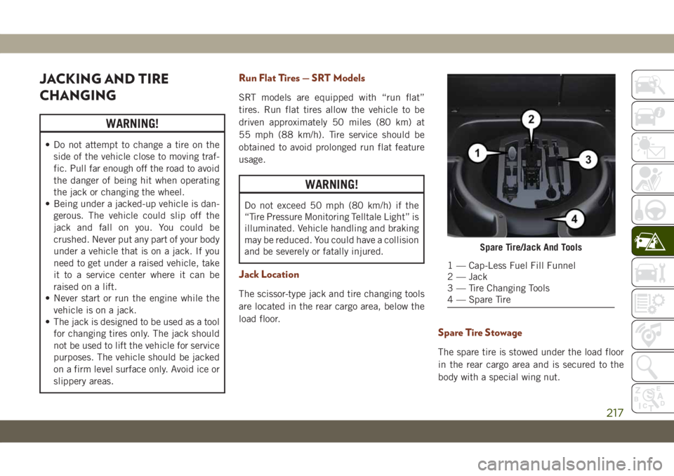
The scissor-type jack and tire changing tools
are located in the rear cargo area, below the
load floor.
Spare Tire Stowage
The spare tire is stowed under the load floor
in the rear cargo area and is secured to the
body with a special wing nut.
Spare Tire/Jack And Tools
1 — Cap-Less Fuel Fill Funnel
2 — Jack
3 — Tire Changing Tools
4 — Spare Tire
217
Page 220 of 378
Preparations For Jacking
CAUTION!
Always lift or jack the vehicle from the
correct jacking points. Failure to follow
this information could cause damage to
the vehicle or underbody components.
NOTE:
To assist with changing a spare tire, the air
suspension system (if equipped) has a fea-
ture which allows the automatic leveling to
be disabled.
1. Park the vehicle on a firm, level surface.
Avoid ice or slippery surfaces.
WARNING!
Do not attempt to change a tire on the side
of the vehicle close to moving traffic. Pull
far enough off the road to avoid being hit
when operating the jack or changing the
wheel.
2. Turn on the Hazard Warning flasher.
3. Apply the parking brake.4. Place the gear selector into PARK.
5. Turn the ignition OFF.
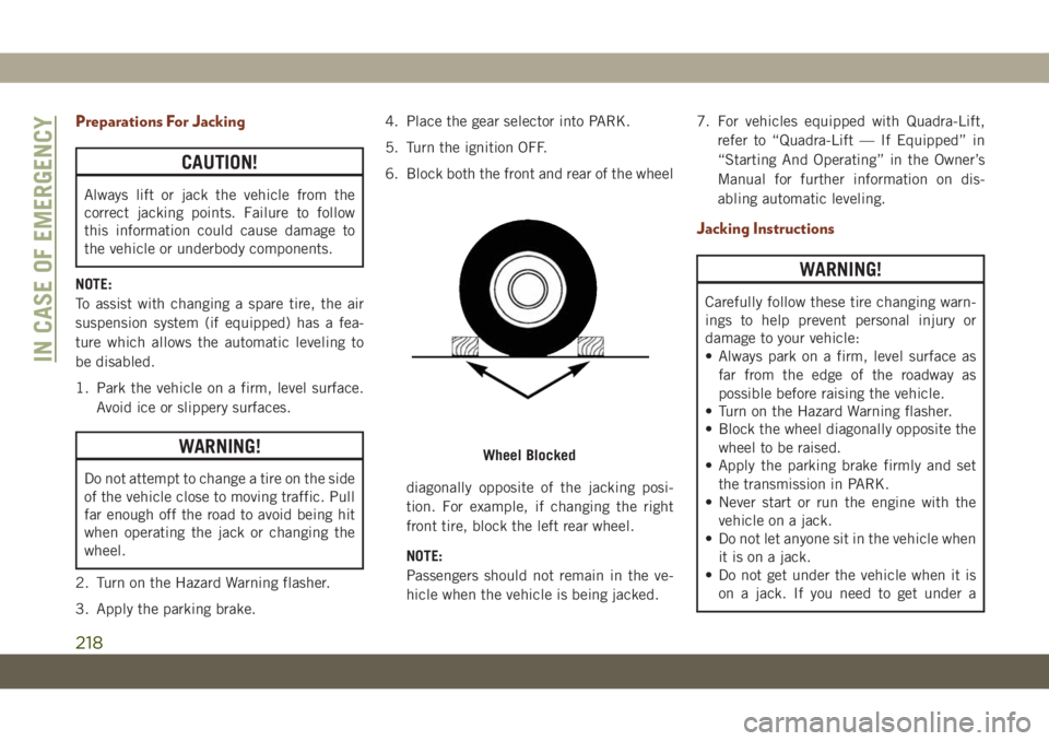
6. Block both the front and rear of the wheel
diagonally opposite of the jacking posi-
tion. For example, if changing the right
front tire, block the left rear wheel.
NOTE:
Passengers should not remain in the ve-
hicle when the vehicle is being jacked.7. For vehicles equipped with Quadra-Lift,
refer to “Quadra-Lift — If Equipped” in
“Starting And Operating” in the Owner’s
Manual for further information on dis-
abling automatic leveling.
Jacking Instructions
WARNING!
Carefully follow these tire changing warn-
ings to help prevent personal injury or
damage to your vehicle:
• Always park on a firm, level surface as
far from the edge of the roadway as
possible before raising the vehicle.
• Turn on the Hazard Warning flasher.
• Block the wheel diagonally opposite the
wheel to be raised.
• Apply the parking brake firmly and set
the transmission in PARK.
• Never start or run the engine with the
vehicle on a jack.
• Do not let anyone sit in the vehicle when
it is on a jack.
• Do not get under the vehicle when it is
on a jack. If you need to get under a
Wheel Blocked
IN CASE OF EMERGENCY
218
Page 221 of 378
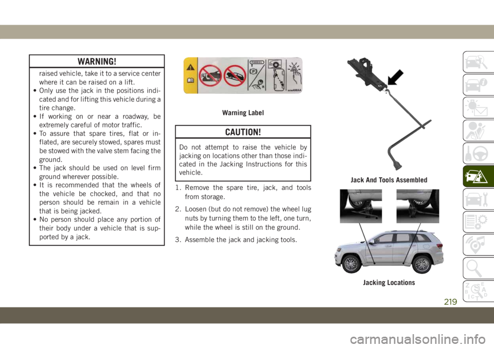
WARNING!
raised vehicle, take it to a service center
where it can be raised on a lift.
• Only use the jack in the positions indi-
cated and for lifting this vehicle during a
tire change.
• If working on or near a roadway, be
extremely careful of motor traffic.
• To assure that spare tires, flat or in-
flated, are securely stowed, spares must
be stowed with the valve stem facing the
ground.
• The jack should be used on level firm
ground wherever possible.
• It is recommended that the wheels of
the vehicle be chocked, and that no
person should be remain in a vehicle
that is being jacked.
• No person should place any portion of
their body under a vehicle that is sup-
ported by a jack.
CAUTION!
Do not attempt to raise the vehicle by
jacking on locations other than those indi-
cated in the Jacking Instructions for this
vehicle.
1. Remove the spare tire, jack, and tools
from storage.
2. Loosen (but do not remove) the wheel lug
nuts by turning them to the left, one turn,
while the wheel is still on the ground.
3. Assemble the jack and jacking tools.
Warning Label
Jack And Tools Assembled
Jacking Locations
219
Page 227 of 378
Jack Usage Precautions
To complete the Use and Maintenance Hand-
book to which this supplement is attached,
given below are some instructions on the
proper use of the jack.
WARNING!
When using the crank, make sure it turns
freely without the risk of scraping hands
against the ground.
Even the moving parts of the jack, the
“worm screw” and joints can cause inju-
ries: avoid contact with them. Clean it
thoroughly if dirtied with grease.
CAUTION!
The jack is a tool designed exclusively for
changing a wheel, in case of a puncture or
damage to a tire of the vehicle on which it
is fitted or on vehicles of the same model.
Any other use, e.g. to jack up other vehicle
models or different things, is strictly pro-
hibited. Never use it to carry out mainte-
nance or repairs under the vehicle or to
CAUTION!
change summer/winter wheels and vice
versa. Never go under the raised vehicle. If
any work under the vehicle is necessary,
contact an authorized dealer. Incorrect
placing of the jack can cause the vehicle to
drop: use it only in the positions indicated.
Do not use the jack for loads higher than
that specified on the label. Never start the
engine with vehicle raised. If the vehicle is
raised more than necessary, everything
can become more unstable, with the risk of
the vehicle dropping violently. Therefore
raise the vehicle only as much as neces-
sary for the wheel/spare.
Maintenance
• Make sure grime does not build up on the
“worm screw.”
• Keep the “worm screw” lubricated.
• Never modify the jack.
Conditions Of Non-Use:
• Temperatures below −40°F (-40°C).
• On sandy or muddy ground.
• On uneven ground.• On steep roads.
• In extreme weather conditions: thunder-
storms, typhoons, hurricanes, blizzards,
storms, etc.
NOTE:
• The jack requires no adjustment.
• The jack cannot be repaired, and in the
event of a fault, it must be replaced by
another genuine one.
• No tool other than its cranking device may
be fitted on the jack.
JUMP STARTING
If your vehicle has a discharged battery, it can
be jump started using a set of jumper cables
and a battery in another vehicle, or by using a
portable battery booster pack. Jump starting
can be dangerous if done improperly, so
please follow the procedures in this section
carefully.
225