light JEEP GRAND CHEROKEE 2020 Owner handbook (in English)
[x] Cancel search | Manufacturer: JEEP, Model Year: 2020, Model line: GRAND CHEROKEE, Model: JEEP GRAND CHEROKEE 2020Pages: 378, PDF Size: 6.88 MB
Page 145 of 378
WARNING!
• NEVER place any objects under the floor
mat (e.g., towels, keys, etc.). These ob-
jects could change the position of the
floor mat and may cause interference
with the accelerator, brake, or clutch
pedals.
• If the vehicle carpet has been removed
and re-installed, always properly attach
carpet to the floor and check the floor
mat fasteners are secure to the vehicle
carpet. Fully depress each pedal to
check for interference with the accelera-
tor, brake, or clutch pedals then re-
install the floor mats.
• It is recommended to only use mild soap
and water to clean your floor mats. After
cleaning, always check your floor mat
has been properly installed and is se-
cured to your vehicle using the floor mat
fasteners by lightly pulling mat.
Periodic Safety Checks You Should Make
Outside The Vehicle
Tires
Examine tires for excessive tread wear and
uneven wear patterns. Check for stones,
nails, glass, or other objects lodged in the
tread or sidewall. Inspect the tread for cuts
and cracks. Inspect sidewalls for cuts,
cracks, and bulges. Check the wheel nuts for
tightness. Check the tires (including spare)
for proper cold inflation pressure.
Lights
Have someone observe the operation of brake
lights and exterior lights while you work the
controls. Check turn signal and high beam
indicator lights on the instrument panel.
Door Latches
Check for proper closing, latching, and locking.
Fluid Leaks
Check area under the vehicle after overnight
parking for fuel, coolant, oil, or other fluid
leaks. Also, if gasoline fumes are detected or
if fuel, or brake fluid leaks are suspected. The
cause should be located and corrected
immediately.
WARNING!
To prevent SERIOUS INJURY or DEATH
when using “Track-Use” parts and equip-
ment:
• NEVER use any “Track-Use” equipment
on public roads. FCA does not authorize
the use of “Track-Use” equipment on
public roads.
• The intended use of “Track-Use” parts is
for race vehicles on race tracks. To help
ensure the safety of the race driver, en-
gineers should supervise the installation
of “Track-Use” parts.
• FCA does not authorize the installation
or use of any part noted as “Track-Use”
on any new vehicle prior to its first retail
sale.
143
Page 151 of 378
WARNING!
fatally injured. Children should be
warned not to touch the parking brake,
brake pedal or the gear selector.
• Do not leave the key fob in or near the
vehicle, or in a location accessible to
children, and do not leave the ignition of
a vehicle equipped with Keyless Enter-
N-Go in the ACC or ON/RUN mode. A
child could operate power windows,
other controls, or move the vehicle.
• Do not leave children or animals inside
parked vehicles in hot weather. Interior
heat build-up may cause serious injury
or death.
NOTE:
Engine start up in very low ambient tempera-
ture could result in evident white smoke. This
condition will disappear as the engine warms
up.
CAUTION!
• The engine is allowed to crank as long as
30 seconds. If the engine fails to start
during this period, please wait at least
two minutes for the starter to cool before
repeating start procedure.
• If the “Water in Fuel Indicator Light”
remains on, DO NOT START engine be-
fore you drain the water from the fuel
filters to avoid engine damage. Refer to
“Draining Fuel/Water Separator Filter”
in “Servicing And Maintenance” in your
Diesel Supplement for further informa-
tion, which can be found with your on-
line Owner’s Information.
Automatic Transmission
Start the engine with the transmission gear
selector in the PARK position. Apply the
brake before shifting to any driving range.
Normal Starting
Observe the instrument panel cluster lights
when starting the engine.
NOTE:
Normal starting of either a cold or a warm
engine is obtained without pumping or press-
ing the accelerator pedal
1. Always apply the parking brake.
2. Press and hold the brake pedal while
pushing the ENGINE START/STOP button
once.
NOTE:
A delay of the start of up to five seconds is
possible under very cold conditions. The
"Wait to Start" telltale will be illuminated
during the pre-heat process, When the
engine Wait To Start light goes off the
engine will automatically crank.
CAUTION!
If the “Water in Fuel Indicator Light” re-
mains on, DO NOT START engine before
you drain the water from the fuel filters to
149
Page 152 of 378
CAUTION!
avoid engine damage. Refer to “Draining
Fuel/Water Separator Filter” in “Servicing
And Maintenance” in your Diesel Supple-
ment for further information, which can be
found with your online Owner’s Informa-
tion.
3. The system will automatically engage the
starter to crank the engine. If the vehicle
fails to start, the starter will disengage
automatically after 25 seconds.
4. If you wish to stop the cranking of the
engine prior to the engine starting, push
the button again.
5. Check that the oil pressure warning light
has turned off.
6. Release the parking brake.NOTE:
Only press one pedal at a time while driving
the vehicle. Torque performance of the ve-
hicle could be reduced if both pedals are
pressed at the same time. If pressure is
detected on both pedals simultaneously, a
warning message will display in the instru-
ment cluster. For further information, refer to
“Instrument Cluster Display” in “Getting To
Know Your Instrument Panel”.
STOP/START SYSTEM — IF
EQUIPPED
The Stop/Start function is developed to re-
duce fuel consumption. The system will stop
the engine automatically during a vehicle
stop if the required conditions are met. Re-
leasing the brake pedal or pressing the accel-
erator pedal will automatically re-start the
engine.
This vehicle has been upgraded with a heavy
duty starter, enhanced battery, and other up-
graded engine parts, to handle the additional
engine starts.
Automatic Mode
The Stop/Start feature is enabled
after every normal customer en-
gine start. At that time, the sys-
tem will go into STOP/START
READY and if all other conditions are met,
can go into a STOP/START AUTOSTOP AC-
TIVE “Autostop” mode.
To Activate The Autostop Mode, The Following
Must Occur:
• The system must be in STOP/START
READY state. A STOP/START READY mes-
sage will be displayed in the instrument
cluster display within the Stop/Start sec-
tion. Refer to “Instrument Cluster” in “Get-
ting To Know Your Instrument Panel” in
your Owner’s Manual for further informa-
tion.
• The vehicle must be completely stopped.
• The shifter must be in a forward gear and
the brake pedal depressed.
STARTING AND OPERATING
150
Page 154 of 378
• STOP/START OFF switch is pushed.
• A STOP/START system error occurs.
• 4WD system is put into 4LO mode.
To Manually Turn Off The Stop/Start
System
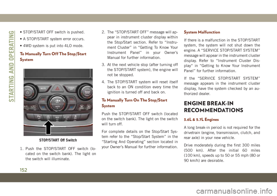
1. Push the STOP/START OFF switch (lo-
cated on the switch bank). The light on
the switch will illuminate.2. The “STOP/START OFF” message will ap-
pear in instrument cluster display within
the Stop/Start section. Refer to “Instru-
ment Cluster” in “Getting To Know Your
Instrument Panel” in your Owner’s
Manual for further information.
3. At the next vehicle stop (after turning off
the STOP/START system), the engine will
not be stopped.
4. The STOP/START system will reset itself
back to an ON condition every time the
ignition is turned off and back on.
To Manually Turn On The Stop/Start
System
Push the STOP/START OFF switch (located
on the switch bank). The light on the switch
will turn off.
For complete details on the Stop/Start Sys-
tem refer to the “Stop/Start System” in the
“Starting And Operating” section located in
your Owner’s Manual for further information.
System Malfunction
If there is a malfunction in the STOP/START
system, the system will not shut down the
engine. A “SERVICE STOP/START SYSTEM”
message will appear in the instrument cluster
display. Refer to “Instrument Cluster Dis-
play“ in “Getting to Know Your Instrument
Panel” for further information.
If the “SERVICE STOP/START SYSTEM”
message appears in the instrument cluster
display, have the system checked by an au-
thorized dealer.
ENGINE BREAK-IN
RECOMMENDATIONS
3.6L & 5.7L Engines
A long break-in period is not required for the
drivetrain (engine, transmission, clutch, and
rear axle) in your new vehicle.
Drive moderately during the first 300 miles
(500 km). After the initial 60 miles
(100 km), speeds up to 50 or 55 mph (80 or
90 km/h) are desirable.
STOP/START Off Switch
STARTING AND OPERATING
152
Page 155 of 378
While cruising, brief full-throttle acceleration
within the limits of local traffic laws contrib-
utes to a good break-in. However, wide-open
throttle acceleration in low gear can be det-
rimental and should be avoided.
The engine oil, transmission fluid, and axle
lubricant installed at the factory is high-
quality and energy-conserving. Oil, fluid, and
lubricant changes should be consistent with
anticipated climate and conditions under
which vehicle operations will occur. For the
recommended viscosity and quality grades,
refer to “Fluids And Lubricants” in "Techni-
cal Specifications”.
CAUTION!
Never use Non-Detergent Oil or Straight
Mineral Oil in the engine or damage may
result.NOTE:
A new engine may consume some oil during
its first few thousand miles (kilometers) of
operation. This should be considered a nor-
mal part of the break-in and not interpreted
as an indication of difficulty. Please check
your oil level with the engine oil indicator
often during the break in period. Add oil as
required.
Diesel Engine
The diesel engine does not require a break-in
period due to its construction. Normal opera-
tion is allowed, providing the following rec-
ommendations are followed:
• Warm up the engine before placing it under
load.
• Do not operate the engine at idle for pro-
longed periods.
• Use the appropriate transmission gear to
prevent engine lugging.
• Observe vehicle oil pressure and tempera-
ture indicators.
• Check the coolant and oil levels frequently.• Vary throttle position at highway speeds
when carrying or towing significant weight.
NOTE:
Light duty operation such as light trailer tow-
ing or no load operation will extend the time
before the engine is at full efficiency. Re-
duced fuel economy and power may be seen
at this time.
The engine oil installed in the engine at the
factory is a high-quality energy conserving
type lubricant. Oil changes should be consis-
tent with anticipated climate conditions un-
der which vehicle operations will occur. The
recommended viscosity and quality grades
are shown under “Fluids And Lubricants” in
"Technical Specifications” in this manual.
NON-DETERGENT OR STRAIGHT MINERAL
OILS MUST NEVER BE USED.
SRT Engines
The following tips will be helpful in obtaining
optimum performance and maximum dura-
bility for your new SRT Vehicle.
Despite modern technology and World Class
manufacturing methods, the moving parts of
the vehicle must still wear in with each other.
153
Page 158 of 378
placing the transmission in PARK. This sys-
tem also locks the transmission in PARK
whenever the ignition is in the OFF mode.
NOTE:
The transmission is NOT locked in PARK
when the ignition is in the ACC mode (even
though the engine will be off). Ensure that
the transmission is in PARK, and the ignition
isOFF(not in ACC mode) before exiting the
vehicle.
Brake/Transmission Shift Interlock
System
This vehicle is equipped with a Brake Trans-
mission Shift Interlock system (BTSI) that
holds the transmission gear selector in PARK
unless the brakes are applied. To shift the
transmission out of PARK, the engine must
be running and the brake pedal must be
pressed. The brake pedal must also be
pressed to shift from NEUTRAL into DRIVE or
REVERSE when the vehicle is stopped or
moving at low speeds.
Fuel Economy (ECO) Mode
The Fuel Economy (ECO) mode can improve
the vehicle's overall fuel economy during nor-
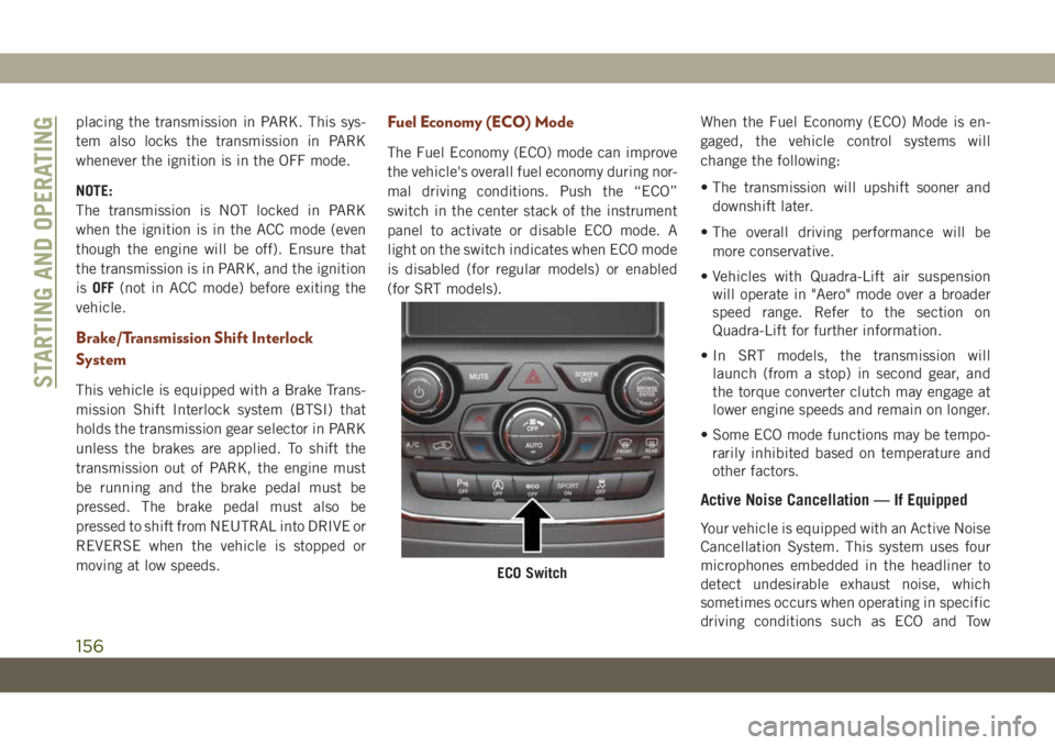
mal driving conditions. Push the “ECO”
switch in the center stack of the instrument
panel to activate or disable ECO mode. A
light on the switch indicates when ECO mode
is disabled (for regular models) or enabled
(for SRT models).When the Fuel Economy (ECO) Mode is en-
gaged, the vehicle control systems will
change the following:
• The transmission will upshift sooner and
downshift later.
• The overall driving performance will be
more conservative.
• Vehicles with Quadra-Lift air suspension
will operate in "Aero" mode over a broader
speed range. Refer to the section on
Quadra-Lift for further information.
• In SRT models, the transmission will
launch (from a stop) in second gear, and
the torque converter clutch may engage at
lower engine speeds and remain on longer.
• Some ECO mode functions may be tempo-
rarily inhibited based on temperature and
other factors.
Active Noise Cancellation — If Equipped
Your vehicle is equipped with an Active Noise
Cancellation System. This system uses four
microphones embedded in the headliner to
detect undesirable exhaust noise, which
sometimes occurs when operating in specific
driving conditions such as ECO and Tow
ECO Switch
STARTING AND OPERATING
156
Page 163 of 378
Shifting Procedures
4WD HI To 4WD LOW
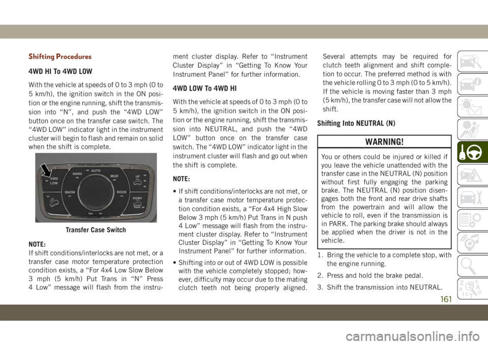
With the vehicle at speeds of 0 to 3 mph (0 to
5 km/h), the ignition switch in the ON posi-
tion or the engine running, shift the transmis-
sion into “N”, and push the “4WD LOW”
button once on the transfer case switch. The
“4WD LOW” indicator light in the instrument
cluster will begin to flash and remain on solid
when the shift is complete.
NOTE:
If shift conditions/interlocks are not met, or a
transfer case motor temperature protection
condition exists, a “For 4x4 Low Slow Below
3 mph (5 km/h) Put Trans in “N” Press
4 Low” message will flash from the instru-ment cluster display. Refer to “Instrument
Cluster Display” in “Getting To Know Your
Instrument Panel” for further information.4WD LOW To 4WD HI
With the vehicle at speeds of 0 to 3 mph (0 to
5 km/h), the ignition switch in the ON posi-
tion or the engine running, shift the transmis-
sion into NEUTRAL, and push the “4WD
LOW” button once on the transfer case
switch. The “4WD LOW” indicator light in the
instrument cluster will flash and go out when
the shift is complete.
NOTE:
• If shift conditions/interlocks are not met, or
a transfer case motor temperature protec-
tion condition exists, a “For 4x4 High Slow
Below 3 mph (5 km/h) Put Trans in N push
4 Low” message will flash from the instru-
ment cluster display. Refer to “Instrument
Cluster Display” in “Getting To Know Your
Instrument Panel” for further information.
• Shifting into or out of 4WD LOW is possible
with the vehicle completely stopped; how-
ever, difficulty may occur due to the mating
clutch teeth not being properly aligned.Several attempts may be required for
clutch teeth alignment and shift comple-
tion to occur. The preferred method is with
the vehicle rolling 0 to 3 mph (0 to 5 km/h).
If the vehicle is moving faster than 3 mph
(5 km/h), the transfer case will not allow the
shift.
Shifting Into NEUTRAL (N)
WARNING!
You or others could be injured or killed if
you leave the vehicle unattended with the
transfer case in the NEUTRAL (N) position
without first fully engaging the parking
brake. The NEUTRAL (N) position disen-
gages both the front and rear drive shafts
from the powertrain and will allow the
vehicle to roll, even if the transmission is
in PARK. The parking brake should always
be applied when the driver is not in the
vehicle.
1. Bring the vehicle to a complete stop, with
the engine running.
2. Press and hold the brake pedal.
3. Shift the transmission into NEUTRAL.
Transfer Case Switch
161
Page 164 of 378
4. If vehicle is equipped with Quadra-Lift air
suspension, ensure the vehicle is set to
Normal Ride Height.
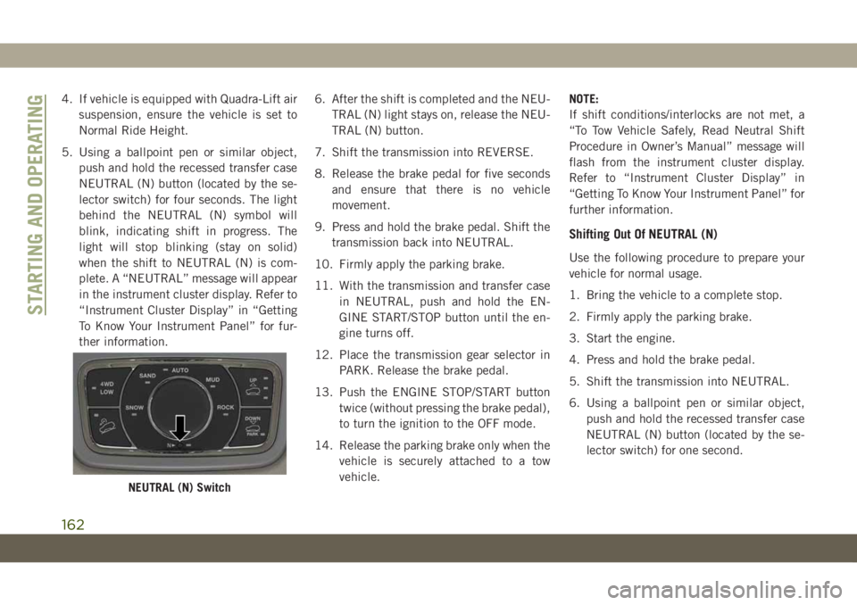
5. Using a ballpoint pen or similar object,
push and hold the recessed transfer case
NEUTRAL (N) button (located by the se-
lector switch) for four seconds. The light
behind the NEUTRAL (N) symbol will
blink, indicating shift in progress. The
light will stop blinking (stay on solid)
when the shift to NEUTRAL (N) is com-
plete. A “NEUTRAL” message will appear
in the instrument cluster display. Refer to
“Instrument Cluster Display” in “Getting
To Know Your Instrument Panel” for fur-
ther information.6. After the shift is completed and the NEU-
TRAL (N) light stays on, release the NEU-
TRAL (N) button.
7. Shift the transmission into REVERSE.
8. Release the brake pedal for five seconds
and ensure that there is no vehicle
movement.
9. Press and hold the brake pedal. Shift the
transmission back into NEUTRAL.
10. Firmly apply the parking brake.
11. With the transmission and transfer case
in NEUTRAL, push and hold the EN-
GINE START/STOP button until the en-
gine turns off.
12. Place the transmission gear selector in
PARK. Release the brake pedal.
13. Push the ENGINE STOP/START button
twice (without pressing the brake pedal),
to turn the ignition to the OFF mode.
14. Release the parking brake only when the
vehicle is securely attached to a tow
vehicle.NOTE:
If shift conditions/interlocks are not met, a
“To Tow Vehicle Safely, Read Neutral Shift
Procedure in Owner’s Manual” message will
flash from the instrument cluster display.
Refer to “Instrument Cluster Display” in
“Getting To Know Your Instrument Panel” for
further information.
Shifting Out Of NEUTRAL (N)
Use the following procedure to prepare your
vehicle for normal usage.
1. Bring the vehicle to a complete stop.
2. Firmly apply the parking brake.
3. Start the engine.
4. Press and hold the brake pedal.
5. Shift the transmission into NEUTRAL.
6. Using a ballpoint pen or similar object,
push and hold the recessed transfer case
NEUTRAL (N) button (located by the se-
lector switch) for one second.
NEUTRAL (N) Switch
STARTING AND OPERATING
162
Page 165 of 378
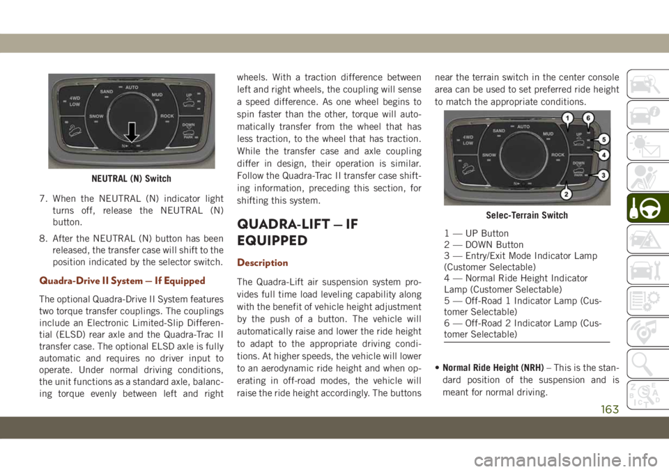
7. When the NEUTRAL (N) indicator light
turns off, release the NEUTRAL (N)
button.
8. After the NEUTRAL (N) button has been
released, the transfer case will shift to the
position indicated by the selector switch.
Quadra-Drive II System — If Equipped
The optional Quadra-Drive II System features
two torque transfer couplings. The couplings
include an Electronic Limited-Slip Differen-
tial (ELSD) rear axle and the Quadra-Trac II
transfer case. The optional ELSD axle is fully
automatic and requires no driver input to
operate. Under normal driving conditions,
the unit functions as a standard axle, balanc-
ing torque evenly between left and rightwheels. With a traction difference between
left and right wheels, the coupling will sense
a speed difference. As one wheel begins to
spin faster than the other, torque will auto-
matically transfer from the wheel that has
less traction, to the wheel that has traction.
While the transfer case and axle coupling
differ in design, their operation is similar.
Follow the Quadra-Trac II transfer case shift-
ing information, preceding this section, for
shifting this system.
QUADRA-LIFT — IF
EQUIPPED
Description
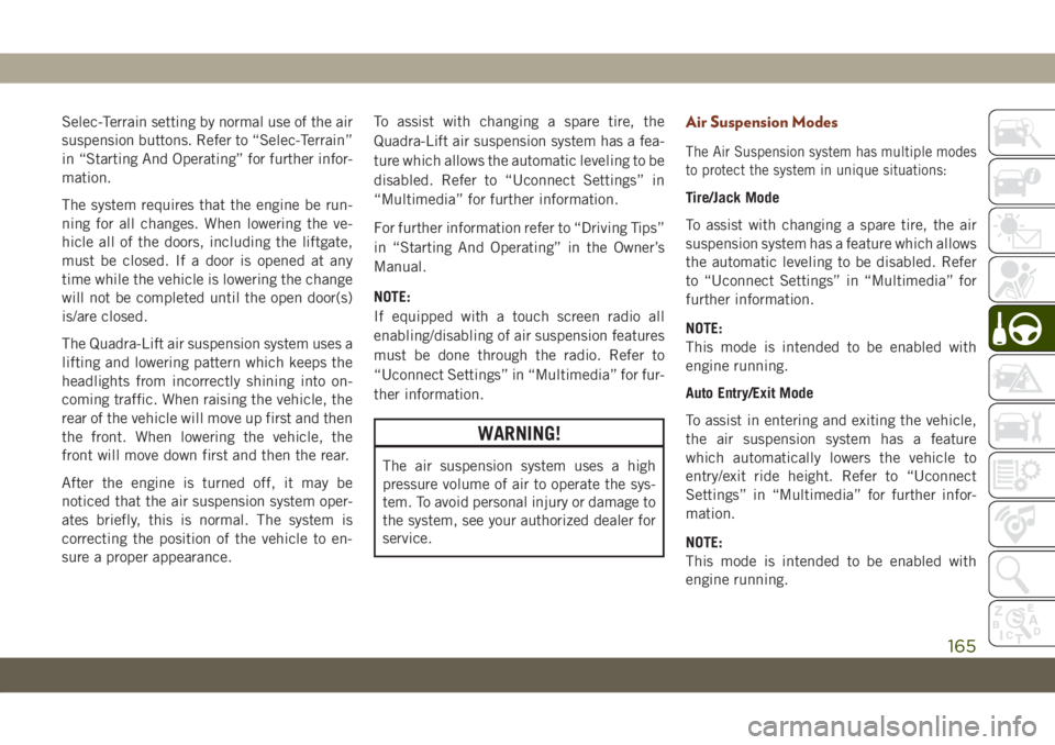
The Quadra-Lift air suspension system pro-
vides full time load leveling capability along
with the benefit of vehicle height adjustment
by the push of a button. The vehicle will
automatically raise and lower the ride height
to adapt to the appropriate driving condi-
tions. At higher speeds, the vehicle will lower
to an aerodynamic ride height and when op-
erating in off-road modes, the vehicle will
raise the ride height accordingly. The buttonsnear the terrain switch in the center console
area can be used to set preferred ride height
to match the appropriate conditions.
•Normal Ride Height (NRH)– This is the stan-
dard position of the suspension and is
meant for normal driving.
NEUTRAL (N) Switch
Selec-Terrain Switch
1 — UP Button
2 — DOWN Button
3 — Entry/Exit Mode Indicator Lamp
(Customer Selectable)
4 — Normal Ride Height Indicator
Lamp (Customer Selectable)
5 — Off-Road 1 Indicator Lamp (Cus-
tomer Selectable)
6 — Off-Road 2 Indicator Lamp (Cus-
tomer Selectable)
163
Page 167 of 378
Selec-Terrain setting by normal use of the air
suspension buttons. Refer to “Selec-Terrain”
in “Starting And Operating” for further infor-
mation.
The system requires that the engine be run-
ning for all changes. When lowering the ve-
hicle all of the doors, including the liftgate,
must be closed. If a door is opened at any
time while the vehicle is lowering the change
will not be completed until the open door(s)
is/are closed.
The Quadra-Lift air suspension system uses a
lifting and lowering pattern which keeps the
headlights from incorrectly shining into on-
coming traffic. When raising the vehicle, the
rear of the vehicle will move up first and then
the front. When lowering the vehicle, the
front will move down first and then the rear.
After the engine is turned off, it may be
noticed that the air suspension system oper-
ates briefly, this is normal. The system is
correcting the position of the vehicle to en-
sure a proper appearance.To assist with changing a spare tire, the
Quadra-Lift air suspension system has a fea-
ture which allows the automatic leveling to be
disabled. Refer to “Uconnect Settings” in
“Multimedia” for further information.
For further information refer to “Driving Tips”
in “Starting And Operating” in the Owner’s
Manual.
NOTE:
If equipped with a touch screen radio all
enabling/disabling of air suspension features
must be done through the radio. Refer to
“Uconnect Settings” in “Multimedia” for fur-
ther information.
WARNING!
The air suspension system uses a high
pressure volume of air to operate the sys-
tem. To avoid personal injury or damage to
the system, see your authorized dealer for
service.
Air Suspension Modes
The Air Suspension system has multiple modes
to protect the system in unique situations:
Tire/Jack Mode
To assist with changing a spare tire, the air
suspension system has a feature which allows
the automatic leveling to be disabled. Refer
to “Uconnect Settings” in “Multimedia” for
further information.
NOTE:
This mode is intended to be enabled with
engine running.
Auto Entry/Exit Mode
To assist in entering and exiting the vehicle,
the air suspension system has a feature
which automatically lowers the vehicle to
entry/exit ride height. Refer to “Uconnect
Settings” in “Multimedia” for further infor-
mation.
NOTE:
This mode is intended to be enabled with
engine running.
165