lock JEEP GRAND CHEROKEE 2020 Owner handbook (in English)
[x] Cancel search | Manufacturer: JEEP, Model Year: 2020, Model line: GRAND CHEROKEE, Model: JEEP GRAND CHEROKEE 2020Pages: 378, PDF Size: 6.88 MB
Page 211 of 378
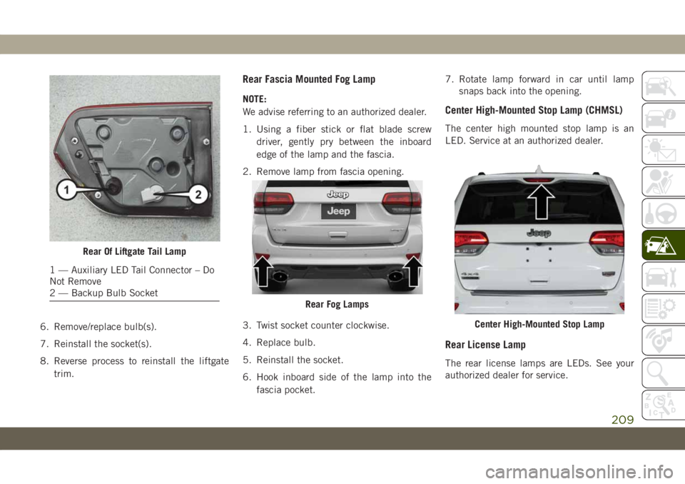
6. Remove/replace bulb(s).
7. Reinstall the socket(s).
8. Reverse process to reinstall the liftgate
trim.
Rear Fascia Mounted Fog Lamp
NOTE:
We advise referring to an authorized dealer.
1. Using a fiber stick or flat blade screw
driver, gently pry between the inboard
edge of the lamp and the fascia.
2. Remove lamp from fascia opening.
3. Twist socket counter clockwise.
4. Replace bulb.
5. Reinstall the socket.
6. Hook inboard side of the lamp into the
fascia pocket.7. Rotate lamp forward in car until lamp
snaps back into the opening.Center High-Mounted Stop Lamp (CHMSL)
The center high mounted stop lamp is an
LED. Service at an authorized dealer.
Rear License Lamp
The rear license lamps are LEDs. See your
authorized dealer for service.
Rear Of Liftgate Tail Lamp
1 — Auxiliary LED Tail Connector – Do
Not Remove
2 — Backup Bulb Socket
Rear Fog Lamps
Center High-Mounted Stop Lamp
209
Page 213 of 378
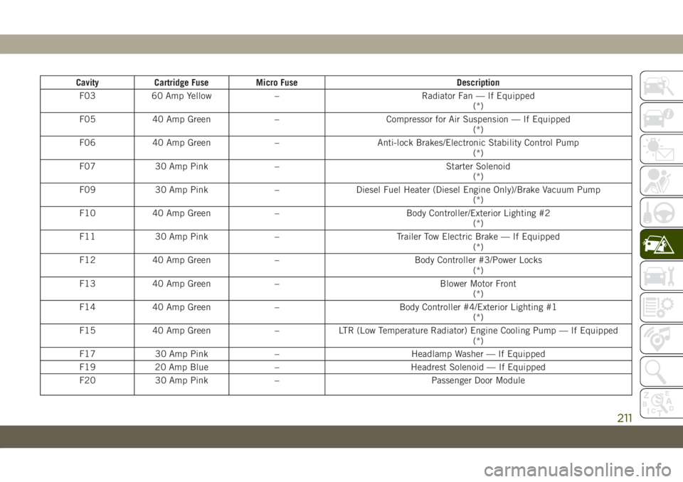
Cavity Cartridge Fuse Micro Fuse Description
F03 60 Amp Yellow – Radiator Fan — If Equipped
(*)
F05 40 Amp Green – Compressor for Air Suspension — If Equipped
(*)
F06 40 Amp Green – Anti-lock Brakes/Electronic Stability Control Pump
(*)
F07 30 Amp Pink – Starter Solenoid
(*)
F09 30 Amp Pink – Diesel Fuel Heater (Diesel Engine Only)/Brake Vacuum Pump
(*)
F10 40 Amp Green – Body Controller/Exterior Lighting #2
(*)
F11 30 Amp Pink – Trailer Tow Electric Brake — If Equipped
(*)
F12 40 Amp Green – Body Controller #3/Power Locks
(*)
F13 40 Amp Green – Blower Motor Front
(*)
F14 40 Amp Green – Body Controller #4/Exterior Lighting #1
(*)
F15 40 Amp Green – LTR (Low Temperature Radiator) Engine Cooling Pump — If Equipped
(*)
F17 30 Amp Pink – Headlamp Washer — If Equipped
F19 20 Amp Blue – Headrest Solenoid — If Equipped
F20 30 Amp Pink – Passenger Door Module
211
Page 214 of 378
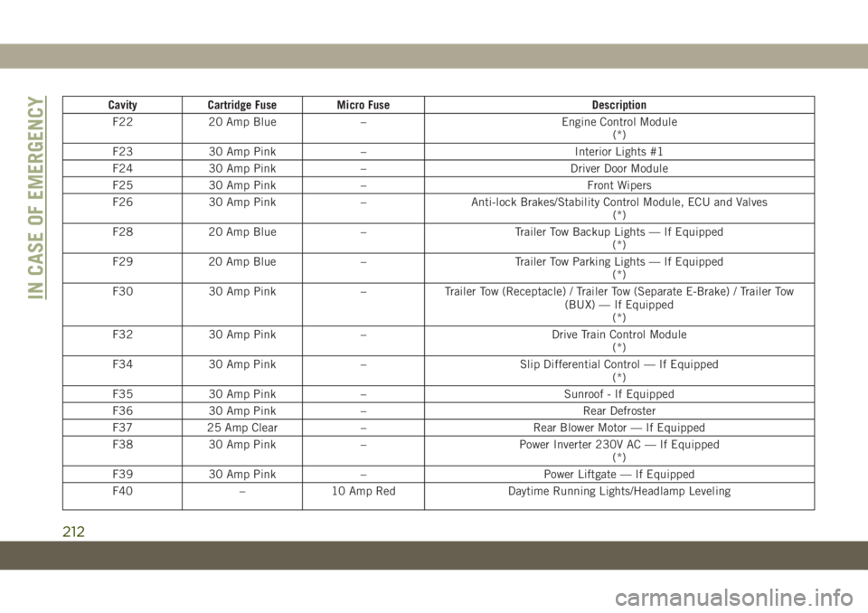
Cavity Cartridge Fuse Micro Fuse Description
F22 20 Amp Blue – Engine Control Module
(*)
F23 30 Amp Pink – Interior Lights #1
F24 30 Amp Pink – Driver Door Module
F25 30 Amp Pink – Front Wipers
F26 30 Amp Pink – Anti-lock Brakes/Stability Control Module, ECU and Valves
(*)
F28 20 Amp Blue – Trailer Tow Backup Lights — If Equipped
(*)
F29 20 Amp Blue – Trailer Tow Parking Lights — If Equipped
(*)
F30 30 Amp Pink – Trailer Tow (Receptacle) / Trailer Tow (Separate E-Brake) / Trailer Tow
(BUX) — If Equipped
(*)
F32 30 Amp Pink – Drive Train Control Module
(*)
F34 30 Amp Pink – Slip Differential Control — If Equipped
(*)
F35 30 Amp Pink – Sunroof - If Equipped
F36 30 Amp Pink – Rear Defroster
F37 25 Amp Clear – Rear Blower Motor — If Equipped
F38 30 Amp Pink – Power Inverter 230V AC — If Equipped
(*)
F39 30 Amp Pink – Power Liftgate — If Equipped
F40 – 10 Amp Red Daytime Running Lights/Headlamp Leveling
IN CASE OF EMERGENCY
212
Page 215 of 378
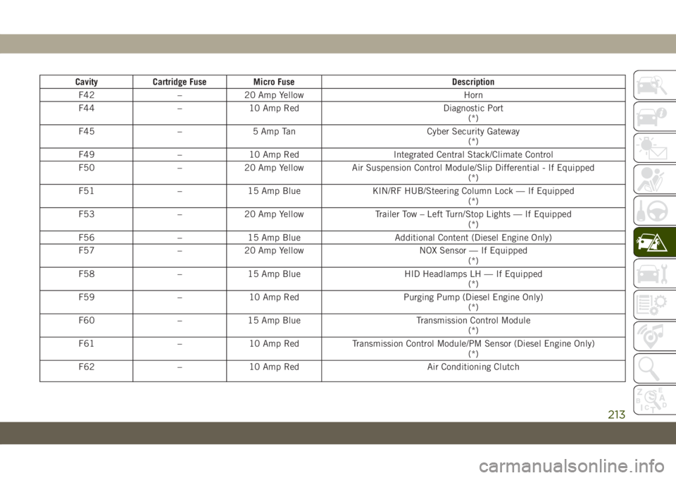
Cavity Cartridge Fuse Micro Fuse Description
F42 – 20 Amp Yellow Horn
F44 – 10 Amp Red Diagnostic Port
(*)
F45 – 5 Amp Tan Cyber Security Gateway
(*)
F49 – 10 Amp Red Integrated Central Stack/Climate Control
F50 – 20 Amp Yellow Air Suspension Control Module/Slip Differential - If Equipped
(*)
F51 – 15 Amp Blue KIN/RF HUB/Steering Column Lock — If Equipped
(*)
F53 – 20 Amp Yellow Trailer Tow – Left Turn/Stop Lights — If Equipped
(*)
F56 – 15 Amp Blue Additional Content (Diesel Engine Only)
F57 – 20 Amp Yellow NOX Sensor — If Equipped
(*)
F58 – 15 Amp Blue HID Headlamps LH — If Equipped
(*)
F59 – 10 Amp Red Purging Pump (Diesel Engine Only)
(*)
F60 – 15 Amp Blue Transmission Control Module
(*)
F61 – 10 Amp Red Transmission Control Module/PM Sensor (Diesel Engine Only)
(*)
F62 – 10 Amp Red Air Conditioning Clutch
213
Page 216 of 378
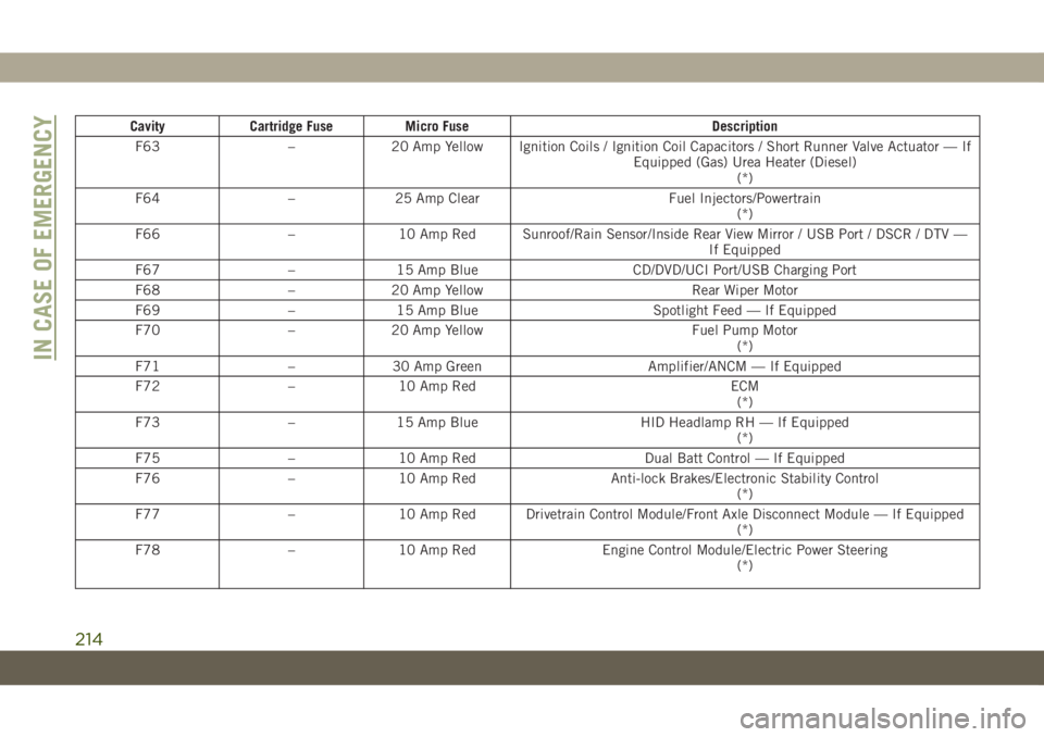
Cavity Cartridge Fuse Micro Fuse Description
F63 – 20 Amp Yellow Ignition Coils / Ignition Coil Capacitors / Short Runner Valve Actuator — If
Equipped (Gas) Urea Heater (Diesel)
(*)
F64 – 25 Amp Clear Fuel Injectors/Powertrain
(*)
F66 – 10 Amp Red Sunroof/Rain Sensor/Inside Rear View Mirror / USB Port / DSCR / DTV —
If Equipped
F67 – 15 Amp Blue CD/DVD/UCI Port/USB Charging Port
F68 – 20 Amp Yellow Rear Wiper Motor
F69 – 15 Amp Blue Spotlight Feed — If Equipped
F70 – 20 Amp Yellow Fuel Pump Motor
(*)
F71 – 30 Amp Green Amplifier/ANCM — If Equipped
F72 – 10 Amp Red ECM
(*)
F73 – 15 Amp Blue HID Headlamp RH — If Equipped
(*)
F75 – 10 Amp Red Dual Batt Control — If Equipped
F76 – 10 Amp Red Anti-lock Brakes/Electronic Stability Control
(*)
F77 – 10 Amp Red Drivetrain Control Module/Front Axle Disconnect Module — If Equipped
(*)
F78 – 10 Amp Red Engine Control Module/Electric Power Steering
(*)
IN CASE OF EMERGENCY
214
Page 220 of 378
Preparations For Jacking
CAUTION!
Always lift or jack the vehicle from the
correct jacking points. Failure to follow
this information could cause damage to
the vehicle or underbody components.
NOTE:
To assist with changing a spare tire, the air
suspension system (if equipped) has a fea-
ture which allows the automatic leveling to
be disabled.
1. Park the vehicle on a firm, level surface.
Avoid ice or slippery surfaces.
WARNING!
Do not attempt to change a tire on the side
of the vehicle close to moving traffic. Pull
far enough off the road to avoid being hit
when operating the jack or changing the
wheel.
2. Turn on the Hazard Warning flasher.
3. Apply the parking brake.4. Place the gear selector into PARK.
5. Turn the ignition OFF.
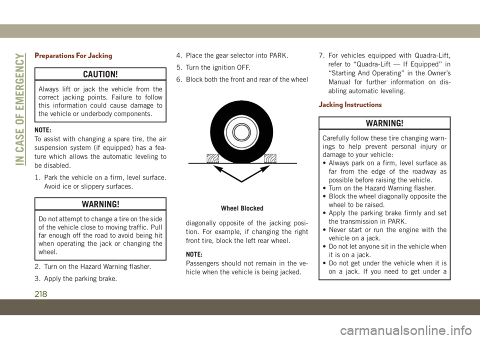
6. Block both the front and rear of the wheel
diagonally opposite of the jacking posi-
tion. For example, if changing the right
front tire, block the left rear wheel.
NOTE:
Passengers should not remain in the ve-
hicle when the vehicle is being jacked.7. For vehicles equipped with Quadra-Lift,
refer to “Quadra-Lift — If Equipped” in
“Starting And Operating” in the Owner’s
Manual for further information on dis-
abling automatic leveling.
Jacking Instructions
WARNING!
Carefully follow these tire changing warn-
ings to help prevent personal injury or
damage to your vehicle:
• Always park on a firm, level surface as
far from the edge of the roadway as
possible before raising the vehicle.
• Turn on the Hazard Warning flasher.
• Block the wheel diagonally opposite the
wheel to be raised.
• Apply the parking brake firmly and set
the transmission in PARK.
• Never start or run the engine with the
vehicle on a jack.
• Do not let anyone sit in the vehicle when
it is on a jack.
• Do not get under the vehicle when it is
on a jack. If you need to get under a
Wheel Blocked
IN CASE OF EMERGENCY
218
Page 222 of 378
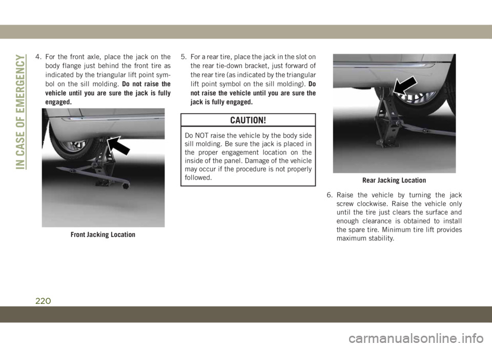
4. For the front axle, place the jack on the
body flange just behind the front tire as
indicated by the triangular lift point sym-
bol on the sill molding.Do not raise the
vehicle until you are sure the jack is fully
engaged.5. For a rear tire, place the jack in the slot on
the rear tie-down bracket, just forward of
the rear tire (as indicated by the triangular
lift point symbol on the sill molding).Do
not raise the vehicle until you are sure the
jack is fully engaged.
CAUTION!
Do NOT raise the vehicle by the body side
sill molding. Be sure the jack is placed in
the proper engagement location on the
inside of the panel. Damage of the vehicle
may occur if the procedure is not properly
followed.
6. Raise the vehicle by turning the jack
screw clockwise. Raise the vehicle only
until the tire just clears the surface and
enough clearance is obtained to install
the spare tire. Minimum tire lift provides
maximum stability.
Front Jacking Location
Rear Jacking Location
IN CASE OF EMERGENCY
220
Page 223 of 378
WARNING!
Raising the vehicle higher than necessary
can make the vehicle less stable. It could
slip off the jack and hurt someone near it.
Raise the vehicle only enough to remove
the tire.
7. Remove the lug nuts and wheel.
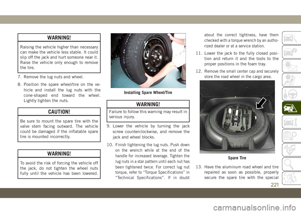
8. Position the spare wheel/tire on the ve-
hicle and install the lug nuts with the
cone-shaped end toward the wheel.
Lightly tighten the nuts.
CAUTION!
Be sure to mount the spare tire with the
valve stem facing outward. The vehicle
could be damaged if the inflatable spare
tire is mounted incorrectly.
WARNING!
To avoid the risk of forcing the vehicle off
the jack, do not tighten the wheel nuts
fully until the vehicle has been lowered.
WARNING!
Failure to follow this warning may result in
serious injury.
9. Lower the vehicle by turning the jack
screw counterclockwise, and remove the
jack and wheel blocks.
10. F
inish tightening the lug nuts. Push down
on the wrench while at the end of the
handle for increased leverage. Tighten the
lug nuts in a star pattern until each nut has
been tightened twice. For correct lug nut
torque, refer to “Torque Specifications” in
“Technical Specifications”. If in doubtabout the correct tightness, have them
checked with a torque wrench by an autho-
rized dealer or at a service station.
11. Lower the jack to the fully closed posi-
tion and return it and the tools to the
proper positions in the foam tray.
12. R
emove the small center cap and securely
store the road wheel in the cargo area.
13. Have the aluminum road wheel and tire
repaired as soon as possible, properly
secure the spare tire with the special
Installing Spare Wheel/Tire
Spare Tire
221
Page 224 of 378
wing nut torqued to 3.7 ft-lbs (5 N·m),
reinstall the jack and tool kit foam tray,
and latch the rear load floor cover.
NOTE:
Do not drive with the spare tire installed for
more than 50 miles (80 km) at a max speed
of 50 mph (80 km/h).
WARNING!
A loose tire or jack thrown forward in a
collision or hard stop could endanger the
occupants of the vehicle. Always stow the
jack parts and the spare tire in the places
provided. Have the deflated (flat) tire re-
paired or replaced immediately.
Road Tire Installation
1. Mount the road tire on the axle.
2. Install the remaining lug nuts with the
cone shaped end of the nut toward the
wheel. Lightly tighten the lug nuts.
WARNING!
To avoid the risk of forcing the vehicle off
the jack, do not tighten the wheel nuts
fully until the vehicle has been lowered.
Failure to follow this warning may result in
serious injury.
3. Lower the vehicle to the ground by turning
the jack handle counterclockwise.
4. Refer to “Torque Specifications” in
“Technical Specifications” for proper lug
nut torque.
5. After 25 miles (40 km), check the lug nut
torque with a torque wrench to ensure that
all lug nuts are properly seated against the
wheel.
Declaration Of Conformance
1. The undersigned, Tony Fabiano, repre-
senting the manufacturer, herewith de-
clares that the machinery described be-
low fulfills all relevant provisions of:
• The EC-directive 2006/42/EC on
Machinery
2. Description of machinery.
a) Generic Denomination: Vehicle Jack
b) Function: Lifting Vehicle
d)Vehicle
Modelc)Model
Codef)Working
Loade)Jack
Type
Jeep®
CompassMK 1200 kg
MaxFGMF1
Jeep
CherokeeKL 1000 kg
MaxFGLF1
Jeep
WranglerJK 1000 kg
MaxFGLF2
Jeep
Grand
CherokeeWK 1700 kg
MaxFGLF3
IN CASE OF EMERGENCY
222
Page 232 of 378
CAUTION!
Closing the armrest while the Manual Park
Release is activated may damage the
Manual Park Release mechanism, the
transmission, and/or the armrest.
NOTE:
To prevent the vehicle from rolling uninten-
tionally, firmly apply the parking brake.To Disengage The Manual Park Release Le-
ver:
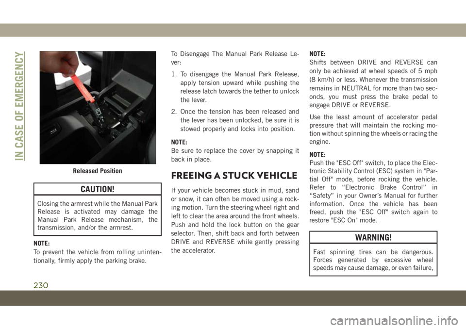
1. To disengage the Manual Park Release,
apply tension upward while pushing the
release latch towards the tether to unlock
the lever.
2. Once the tension has been released and
the lever has been unlocked, be sure it is
stowed properly and locks into position.
NOTE:
Be sure to replace the cover by snapping it
back in place.
FREEING A STUCK VEHICLE
If your vehicle becomes stuck in mud, sand
or snow, it can often be moved using a rock-
ing motion. Turn the steering wheel right and
left to clear the area around the front wheels.
Push and hold the lock button on the gear
selector. Then, shift back and forth between
DRIVE and REVERSE while gently pressing
the accelerator.NOTE:
Shifts between DRIVE and REVERSE can
only be achieved at wheel speeds of 5 mph
(8 km/h) or less. Whenever the transmission
remains in NEUTRAL for more than two sec-
onds, you must press the brake pedal to
engage DRIVE or REVERSE.
Use the least amount of accelerator pedal
pressure that will maintain the rocking mo-
tion without spinning the wheels or racing the
engine.
NOTE:
Push the "ESC Off" switch, to place the Elec-
tronic Stability Control (ESC) system in "Par-
tial Off" mode, before rocking the vehicle.
Refer to “Electronic Brake Control” in
“Safety” in your Owner’s Manual for further
information. Once the vehicle has been
freed, push the "ESC Off" switch again to
restore "ESC On" mode.
WARNING!
Fast spinning tires can be dangerous.
Forces generated by excessive wheel
speeds may cause damage, or even failure,
Released Position
IN CASE OF EMERGENCY
230