display JEEP GRAND CHEROKEE 2020 Owner handbook (in English)
[x] Cancel search | Manufacturer: JEEP, Model Year: 2020, Model line: GRAND CHEROKEE, Model: JEEP GRAND CHEROKEE 2020Pages: 378, PDF Size: 6.88 MB
Page 9 of 378
COMMANDVIEW SUNROOF WITH POWER SHADE — IF
EQUIPPED........................ 56
Opening Sunroof.................. 57
Closing Sunroof.................. 57
Opening Power Shade............... 57
Closing Power Shade............... 58
Pinch Protect Feature............... 58
Venting Sunroof — Express........... 58
Sunroof Maintenance............... 58
HOOD.......................... 59To Open The Hood................. 59
To Close The Hood................. 59
LIFTGATE......................... 59Opening....................... 59
Closing........................ 60
Power Liftgate — If Equipped......... 61
INTERNAL EQUIPMENT................. 62Power Outlets.................... 62
ROOF LUGGAGE RACK — IF EQUIPPED......... 64
GETTING TO KNOW YOUR
INSTRUMENT PANEL
INSTRUMENT CLUSTER DISPLAY............ 66Instrument Cluster Display Location And
Controls....................... 66
Oil Change Indicator System — If Equipped . 67
Instrument Cluster Display Selectable Items . 67
Display Menu items................ 67
Diesel Displays — If Equipped......... 68
Diesel Particulate Filter (DPF) Messages — If
Equipped...................... 69
Fuel System Messages — If Equipped..... 70
TRIP COMPUTER..................... 73WARNING LIGHTS AND MESSAGES.......... 73
Red Warning Lights................ 73
Yellow Warning Lights............... 76
Yellow Indicator Lights.............. 80
Green Indicator Lights.............. 82
White Indicator Lights.............. 83
Blue Indicator Lights............... 84
ONBOARD DIAGNOSTIC SYSTEM — OBD II...... 85Onboard Diagnostic System (OBD II)
Cybersecurity.................... 85
SAFETY
SAFETY FEATURES................... 86Anti-Lock Brake System (ABS)......... 86
Electronic Brake Control System........ 87
AUXILIARY DRIVING SYSTEMS............. 97Blind Spot Monitoring (BSM) — If Equipped . 97
Forward Collision Warning (FCW) With
Mitigation..................... 101
Tire Pressure Monitor System (TPMS).... 103
OCCUPANT RESTRAINT SYSTEMS.......... 107Occupant Restraint Systems Features.... 107
Important Safety Precautions......... 107
Seat Belt Systems................ 108
Supplemental Restraint Systems (SRS) . . . 117
Child Restraints — Carrying Children
Safely....................... 127
Transporting Pets................ 140
SAFETY TIPS..................... 140Transporting Passengers............ 140
Exhaust Gas................... 141
Safety Checks You Should Make Inside The
Vehicle...................... 141
Periodic Safety Checks You Should Make
Outside The Vehicle............... 143
STARTING AND OPERATING
STARTING THE ENGINE — GAS............ 145Automatic Transmission............. 145
Normal Starting................. 145
STARTING THE ENGINE — 3.0L DIESEL ENGINE . . 148Automatic Transmission............. 149
Normal Starting................. 149
STOP/START SYSTEM — IF EQUIPPED........ 150Automatic Mode................. 150
Possible Reasons The Engine Does Not
Autostop..................... 151
To Start The Engine While In Autostop Mode . . 151To Manually Turn Off The Stop/Start
System...................... 152
T
o Manually Turn On The Stop/Start System . . 152System Malfunction............... 152
ENGINE BREAK-IN RECOMMENDATIONS....... 1523.6L & 5.7L Engines.............. 152
Diesel Engine................... 153
SRT Engines................... 153
AUTOMATIC TRANSMISSION............. 154Ignition Park Interlock.............. 155
Brake/Transmission Shift Interlock System . 156
Fuel Economy (ECO) Mode........... 156
Eight–Speed Automatic Transmission..... 157
SPORT MODE — IF EQUIPPED............ 159
FOUR WHEEL DRIVE OPERATION........... 159
Quadra-Trac I Operating Instructions/Precautions
— If Equipped.................. 159
Quadra-Trac II Operating Instructions/Precautions
— If Equipped.................. 159
Shift Positions.................. 160
Shifting Procedures............... 161
Quadra-Drive II System — If Equipped.... 163
7
Page 10 of 378
QUADRA-LIFT — IF EQUIPPED............ 163Description.................... 163
Air Suspension Modes............. 165
Instrument Cluster Display Messages..... 166
Operation..................... 166
SELEC-TERRAIN — IF EQUIPPED........... 167Selec-Terrain Mode Selection......... 167
Instrument Cluster Display Messages..... 168
SELEC-TRACK — IF EQUIPPED (SRT)........ 168Custom....................... 169
Active Damping System............. 169
Launch Control— If Equipped......... 170
Guidelines For Track Use............ 171
SPEED CONTROL — IF EQUIPPED.......... 172To Activate.................... 173
To Set A Desired Speed............ 173
To Resume Speed................ 173
To Deactivate................... 174
ADAPTIVE CRUISE CONTROL (ACC)
— IF EQUIPPED.................... 174
To Activate/Deactivate.............. 174
To Set A Desired ACC Speed.......... 175
To Resume.................... 175
To Vary The Speed Setting........... 175
Setting The Following Distance In ACC.... 177
PARKSENSE REAR PARK ASSIST — IF EQUIPPED . . 177ParkSense Sensors................ 177
ParkSense Warning Display........... 177
Enabling And Disabling ParkSense...... 178
ParkSense System Usage Precautions.... 178
PARKSENSE FRONT AND REAR PARK ASSIST — IF
EQUIPPED....................... 179
ParkSense Sensors................ 179
Enabling And Disabling ParkSense...... 180
PARKSENSE ACTIVE PARK ASSIST SYSTEM — IF
EQUIPPED....................... 180
Enabling And Disabling The ParkSense Active
Park Assist System................ 181
LANESENSE — IF EQUIPPED............. 181LaneSense Operation.............. 181
Turning LaneSense On Or Off......... 182
LaneSense Warning Message.......... 182
Changing LaneSense Status.......... 183
PARKVIEW REAR BACK UP CAMERA — IF
EQUIPPED....................... 184
REFUELING THE VEHICLE — GASOLINE ENGINE . . . 185
Emergency Fuel Filler Door Release..... 187
REFUELING THE VEHICLE — DIESEL ENGINE.... 188Avoid Using Contaminated Fuel........ 190
AdBlue®(UREA) — If Equipped....... 190
TRAILER TOWING................... 192Trailer Towing Weights (Maximum Trailer Weight
Ratings) — Non SRT.............. 192
Trailer Towing Weights (Maximum Trailer Weight
Ratings) — SRT................. 194
Trailer Hitch Receiver Cover Removal (Summit
Models) — If Equipped............. 194
Trailer Hitch Receiver Cover Removal (SRT
Models) — If Equipped............. 196
RECREATIONAL TOWING (BEHIND MOTORHOME,
ETC.).......................... 198
Towing This Vehicle Behind Another
Vehicle....................... 198
Recreational Towing — Two Wheel Drive
Models....................... 199
Recreational Towing — Quadra-Trac I
(Single-Speed Transfer Case) Four-Wheel Drive
Models....................... 199Recreational Towing — Quadra–Trac II/
Quadra–Drive II Four-Wheel Drive Models . . 200
IN CASE OF EMERGENCY
HAZARD WARNING FLASHERS............ 203
BULB REPLACEMENT................. 204
Replacement Bulbs............... 204
Bulb Replacement................ 206
FUSES......................... 210General Information............... 210
Underhood Fuses................ 210
JACKING AND TIRE CHANGING............ 217Run Flat Tires — SRT Models......... 217
Jack Location................... 217
Spare Tire Stowage............... 217
Preparations For Jacking............ 218
Jacking Instructions............... 218
Road Tire Installation.............. 222
Declaration Of Conformance.......... 222
Jack Usage Precautions............ 225
JUMP STARTING.................... 225Preparations For Jump Start.......... 226
Jump Starting Procedure............ 227
REFUELING IN EMERGENCY.............. 228
IF YOUR ENGINE OVERHEATS............ 228
MANUAL PARK RELEASE............... 229
FREEING A STUCK VEHICLE.............. 230
TOWING A DISABLED VEHICLE............ 231
Without The Key Fob.............. 233
Two-Wheel Drive Models............ 233
Four-Wheel Drive Models............ 233
Tow Eye Usage — If Equipped......... 234
Emergency Tow Hooks — If Equipped.... 235
ENHANCED ACCIDENT RESPONSE SYSTEM (EARS). . 235
TABLE OF CONTENTS
8
Page 11 of 378
EVENT DATA RECORDER (EDR)............ 235
SERVICING AND MAINTENANCE
SCHEDULED SERVICING................ 236Scheduled Servicing — Non SRT....... 236
Scheduled Servicing — SRT.......... 240
Scheduled Servicing — Diesel Engine.... 244
ENGINE COMPARTMENT............... 2483.6L Engine.................... 248
5.7L Engine.................... 249
6.2L Supercharged Engine........... 250
6.4L Engine.................... 251
3.0L Diesel Engine............... 252
Checking Oil Level — Gasoline Engine.... 253
Checking Oil Level — 3.0 Diesel Engine . . . 253
Adding Washer Fluid............... 254
Brake System.................. 255
Automatic Transmission............. 256
Maintenance-Free Battery........... 256
DEALER SERVICE................... 257Air Conditioner Maintenance......... 257
Windshield Wiper Blades............ 258
Cooling System.................. 262
RAISING THE VEHICLE................. 262
TIRES.......................... 262
Tires — General Information......... 262
Tire Types..................... 267
Spare Tires — If Equipped........... 268
Wheel And Wheel Trim Care.......... 270
Tire Chains (Traction Devices) — Non-SRT . 271
Tire Chains (Traction Devices) — SRT.... 272
Tire Rotation Recommendations........ 272
STORING THE VEHICLE................ 273
BODYWORK....................... 274
Preserving The Bodywork............ 274
INTERIORS....................... 275Seats And Fabric Parts............. 275
Plastic And Coated Parts............ 276
Leather Parts................... 276
Glass Surfaces.................. 276
TECHNICAL SPECIFICATIONS
IDENTIFICATION DATA................. 277Vehicle Identification Number......... 277
WHEEL AND TIRE TORQUE SPECIFICATIONS.... 278Torque Specifications.............. 278
DIMENSIONS...................... 279
WHEELS........................ 280
WEIGHTS........................ 281
FUEL REQUIREMENTS — GASOLINE ENGINES.... 282
3.6L Engine.................... 282
5.7L Engine.................... 282
6.2L/6.4L Engine................ 283
Methanol..................... 283
Ethanol....................... 283
Reformulated Gasoline............. 284
Do Not Use E-85 In Non-Flex Fuel Vehicles . 284
CNG And LP Fuel System Modifications . . . 284
Materials Added To Fuel............ 284
Fuel Icon Identification Compliant To
EN16942..................... 284
Carbon Monoxide Warnings.......... 286
FUEL REQUIREMENTS – DIESEL ENGINE....... 287Fuel Icon Identification Compliant To
EN16942..................... 287
NON-SRT FLUID CAPACITIES............. 290
SRT FLUID CAPACITIES................ 291FLUIDS AND LUBRICANTS NON-SRT......... 291
Engine....................... 291
Chassis....................... 294
FLUIDS AND LUBRICANTS — SRT.......... 295Engine....................... 295
Chassis....................... 297
FUEL CONSUMPTION AND CO2EMISSIONS..... 298
MOPAR ACCESSORIES................. 298
Authentic Accessories By Mopar........ 298
MULTIMEDIA
CYBERSECURITY................... 300
UCONNECT 4 WITH 7-INCH DISPLAY......... 301
Uconnect 4 At A Glance............ 301
Drag & Drop Menu Bar............. 302
Radio....................... 303
Android Auto — If Equipped.......... 304
Apple CarPlay Integration — If Equipped . . 305
Apps — If Equipped............... 306
UCONNECT 4C/4C NAV WITH 8.4-INCH DISPLAY . . 307Uconnect 4C/4C NAV At A Glance...... 307
Drag & Drop Menu Bar............. 308
Radio....................... 309
Android Auto — If Equipped.......... 310
Apple CarPlay Integration — If Equipped . . 314
Apps — If Equipped............... 316
UCONNECT SETTINGS................. 316
OFF ROAD PAGES — IF EQUIPPED.......... 317
Off Road Pages Status Bar........... 317
Vehicle Dynamics................ 318
Suspension.................... 318
Pitch And Roll.................. 319
Accessory Gauges................ 319
Selec-Terrain — If Equipped.......... 320
9
Page 14 of 378
INSTRUMENT PANEL
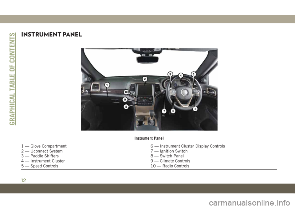
Instrument Panel
1 — Glove Compartment 6 — Instrument Cluster Display Controls
2 — Uconnect System 7 — Ignition Switch
3 — Paddle Shifters 8 — Switch Panel
4 — Instrument Cluster 9 — Climate Controls
5 — Speed Controls 10 — Radio Controls
GRAPHICAL TABLE OF CONTENTS
12
Page 16 of 378
KEYS
Key Fob
Your vehicle uses a keyless ignition system.
The ignition system consists of a key fob with
Remote Keyless Entry (RKE) and a START/
STOP push button ignition system. The Re-
mote Keyless Entry system consists of a key
fob and Keyless Enter-N-Go feature if
equipped.
NOTE:
The key fob may not be found if it is located
next to a mobile phone, laptop or other elec-
tronic device; these devices may block the
key fob’s wireless signal.
The key fob allows you to lock or unlock the
doors and liftgate from distances up to ap-
proximately 66 ft (20 m) using a handheld
key fob. The key fob does not need to be
pointed at the vehicle to activate the system.NOTE:
• With ignition on/start and the vehicle mov-
ing at 5 mph (8 km/h), all RKE commands
are disabled.
CAUTION!
The electrical components inside of the
key fob may be damaged if the key fob is
subjected to strong electrical shocks. In
order to ensure complete efficiency of the
electronic devices inside of the key fob,
avoid exposing the key fob to direct sun-
light.
In case the ignition switch does not change
with the push of a button, the key fob may
have a low or fully depleted battery. A low key
fob battery can be verified by referring to the
instrument cluster, which will display direc-
tions to follow.
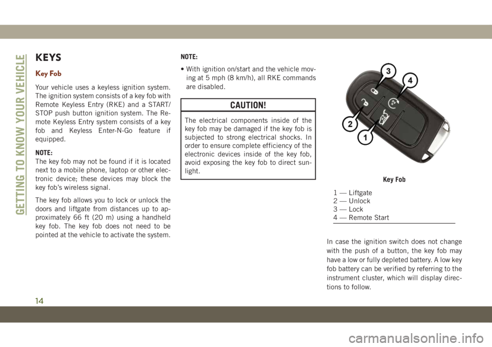
Key Fob
1 — Liftgate
2 — Unlock
3 — Lock
4 — Remote Start
GETTING TO KNOW YOUR VEHICLE
14
Page 28 of 378
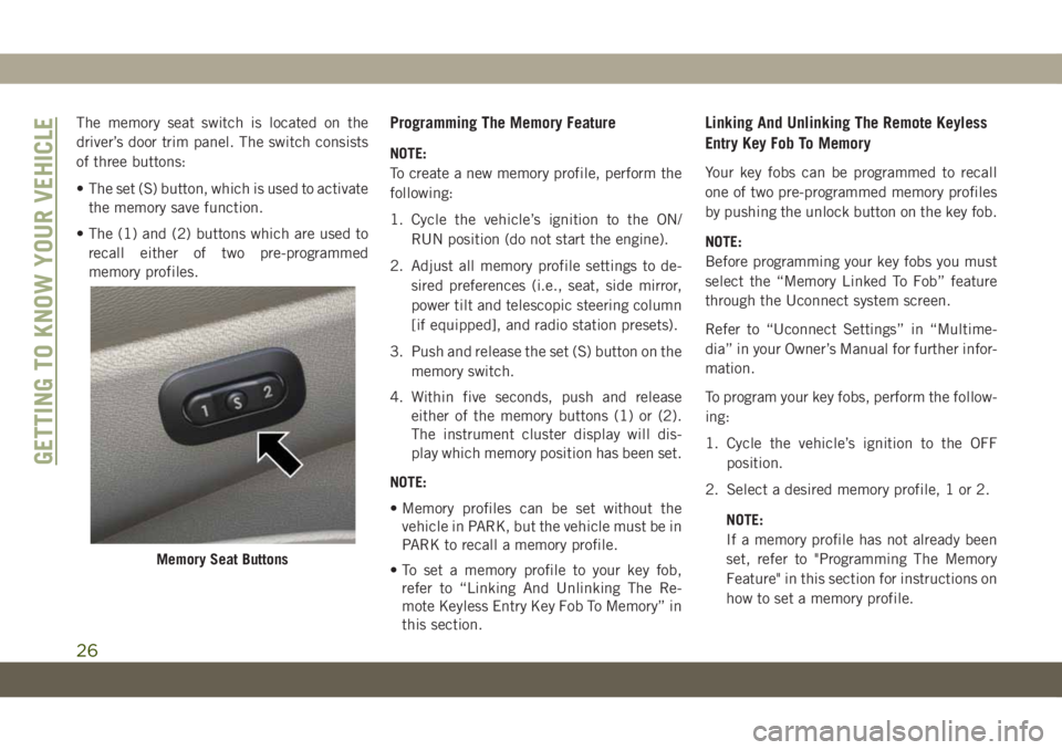
The memory seat switch is located on the
driver’s door trim panel. The switch consists
of three buttons:
• The set (S) button, which is used to activate
the memory save function.
• The (1) and (2) buttons which are used to
recall either of two pre-programmed
memory profiles.Programming The Memory Feature
NOTE:
To create a new memory profile, perform the
following:
1. Cycle the vehicle’s ignition to the ON/
RUN position (do not start the engine).
2. Adjust all memory profile settings to de-
sired preferences (i.e., seat, side mirror,
power tilt and telescopic steering column
[if equipped], and radio station presets).
3. Push and release the set (S) button on the
memory switch.
4. Within five seconds, push and release
either of the memory buttons (1) or (2).
The instrument cluster display will dis-
play which memory position has been set.
NOTE:
• Memory profiles can be set without the
vehicle in PARK, but the vehicle must be in
PARK to recall a memory profile.
• To set a memory profile to your key fob,
refer to “Linking And Unlinking The Re-
mote Keyless Entry Key Fob To Memory” in
this section.
Linking And Unlinking The Remote Keyless
Entry Key Fob To Memory
Your key fobs can be programmed to recall
one of two pre-programmed memory profiles
by pushing the unlock button on the key fob.
NOTE:
Before programming your key fobs you must
select the “Memory Linked To Fob” feature
through the Uconnect system screen.
Refer to “Uconnect Settings” in “Multime-
dia” in your Owner’s Manual for further infor-
mation.
To program your key fobs, perform the follow-
ing:
1. Cycle the vehicle’s ignition to the OFF
position.
2. Select a desired memory profile, 1 or 2.
NOTE:
If a memory profile has not already been
set, refer to "Programming The Memory
Feature" in this section for instructions on
how to set a memory profile.
Memory Seat Buttons
GETTING TO KNOW YOUR VEHICLE
26
Page 29 of 378
3. Once the profile has been recalled, push
and release the set (S) button on the
memory switch.
4. Within five seconds, push and release
button (1) or (2) accordingly. “Memory
Profile Set” (1 or 2) will display in the
instrument cluster.
5. Push and release the lock button on the
key fob within 10 seconds.
NOTE:
Your key fobs can be unlinked to your memory
settings by pushing the set (S) button, and
within 10 seconds, followed by pushing the
unlock button on the key fob.
Memory Position Recall
NOTE:
The vehicle must be in PARK to recall
memory positions. If a recall is attempted
when the vehicle is not in PARK, a message
will be displayed in the instrument cluster
display.Driver One Memory Position Recall
• To recall the memory settings for driver one
using the memory switch, push memory
button (1) on the memory switch.
• To recall the memory settings for driver one
using the key fob, push the unlock button
on the key fob linked to memory position 1.
Driver Two Memory Position Recall
• To recall the memory setting for driver two
using the memory switch, push memory
button (2) on the memory switch.
• To recall the memory settings for driver two
using the key fob, push the unlock button
on the key fob linked to memory position 2.
A recall can be canceled by pushing any of
the memory buttons during a recall (S, 1, or
2), or by pushing any of the seat adjustment
switches. When a recall is canceled, the driv-
er's seat and steering column (if equipped)
stop moving. A delay of one second will occur
before another recall can be selected.
Easy Entry/Exit Seat
This feature provides automatic driver seat
positioning to enhance driver mobility when
entering and exiting the vehicle.
The distance the driver seat moves depends
on where you have the driver seat positioned
when you cycle the vehicle’s ignition to the
OFF position.
• When you cycle the vehicle’s ignition to the
OFF position, the driver seat will move
about 2.4 inches (60 mm) rearward if the
driver seat position is greater than or equal
to 2.7 inches (67.7 mm) forward of the rear
stop. The seat will return to its previously
set position when you cycle the vehicle’s
ignition to the ACC or RUN position.
• The Easy Entry/Easy Exit feature is disabled
when the driver seat position is less than
0.9 of an inch (22.7 mm) forward of the
rear stop. At this position, there is no ben-
efit to the driver by moving the seat for Easy
Exit or Easy Entry.
Each stored memory setting will have an
associated Easy Entry and Easy Exit position.
27
Page 46 of 378
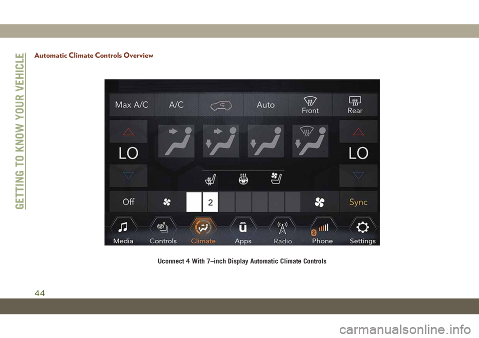
Automatic Climate Controls Overview
Uconnect 4 With 7–inch Display Automatic Climate Controls
GETTING TO KNOW YOUR VEHICLE
44
Page 47 of 378
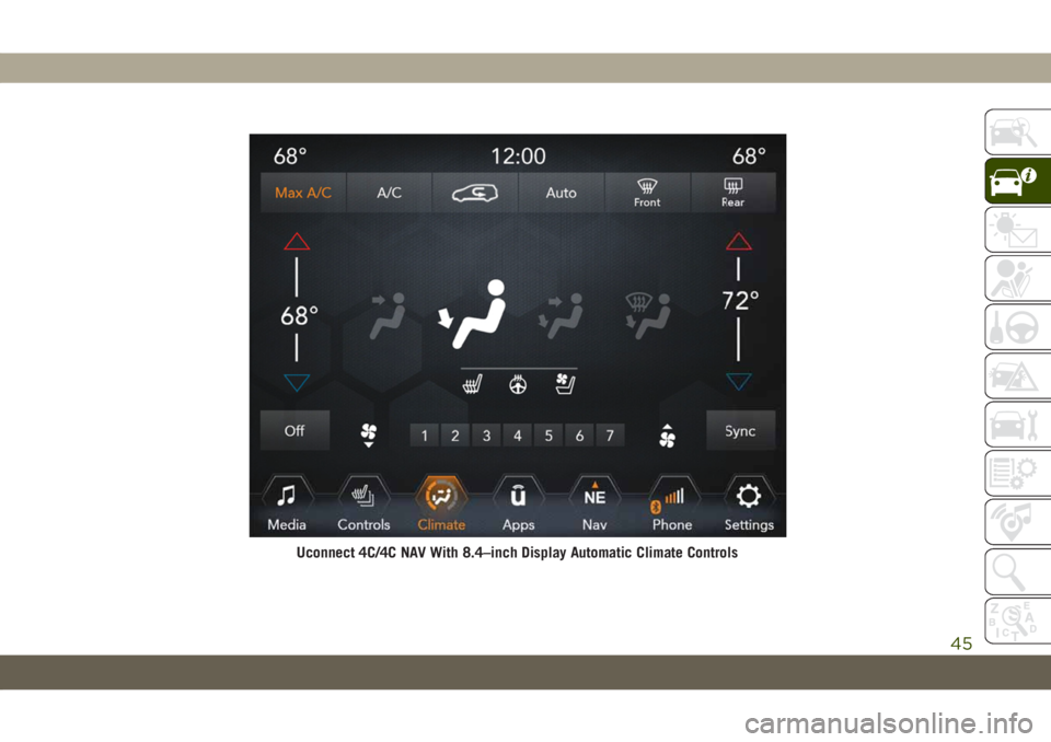
Uconnect 4C/4C NAV With 8.4–inch Display Automatic Climate Controls
45
Page 52 of 378
Climate Control Functions
A/C (Air Conditioning)
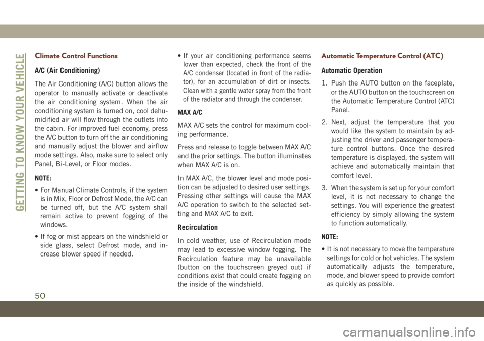
The Air Conditioning (A/C) button allows the
operator to manually activate or deactivate
the air conditioning system. When the air
conditioning system is turned on, cool dehu-
midified air will flow through the outlets into
the cabin. For improved fuel economy, press
the A/C button to turn off the air conditioning
and manually adjust the blower and airflow
mode settings. Also, make sure to select only
Panel, Bi-Level, or Floor modes.
NOTE:
• For Manual Climate Controls, if the system
is in Mix, Floor or Defrost Mode, the A/C can
be turned off, but the A/C system shall
remain active to prevent fogging of the
windows.
• If fog or mist appears on the windshield or
side glass, select Defrost mode, and in-
crease blower speed if needed.•I
f your air conditioning performance seems
lower than expected, check the front of the
A/C condenser (located in front of the radia-
tor), for an accumulation of dirt or insects.
Clean with a gentle water spray from the front
of the radiator and through the condenser.
MAX A/C
MAX A/C sets the control for maximum cool-
ing performance.
Press and release to toggle between MAX A/C
and the prior settings. The button illuminates
when MAX A/C is on.
In MAX A/C, the blower level and mode posi-
tion can be adjusted to desired user settings.
Pressing other settings will cause the MAX
A/C operation to switch to the selected set-
ting and MAX A/C to exit.
Recirculation
In cold weather, use of Recirculation mode
may lead to excessive window fogging. The
Recirculation feature may be unavailable
(button on the touchscreen greyed out) if
conditions exist that could create fogging on
the inside of the windshield.
Automatic Temperature Control (ATC)
Automatic Operation
1. Push the AUTO button on the faceplate,
or the AUTO button on the touchscreen on
the Automatic Temperature Control (ATC)
Panel.
2. Next, adjust the temperature that you
would like the system to maintain by ad-
justing the driver and passenger tempera-
ture control buttons. Once the desired
temperature is displayed, the system will
achieve and automatically maintain that
comfort level.
3. When the system is set up for your comfort
level, it is not necessary to change the
settings. You will experience the greatest
efficiency by simply allowing the system
to function automatically.
NOTE:
• It is not necessary to move the temperature
settings for cold or hot vehicles. The system
automatically adjusts the temperature,
mode, and blower speed to provide comfort
as quickly as possible.
GETTING TO KNOW YOUR VEHICLE
50