Index JEEP LIBERTY 2002 KJ / 1.G User Guide
[x] Cancel search | Manufacturer: JEEP, Model Year: 2002, Model line: LIBERTY, Model: JEEP LIBERTY 2002 KJ / 1.GPages: 1803, PDF Size: 62.3 MB
Page 713 of 1803
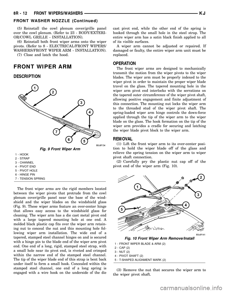
(5) Reinstall the cowl plenum cover/grille panel
over the cowl plenum. (Refer to 23 - BODY/EXTERI-
OR/COWL GRILLE - INSTALLATION).
(6) Reinstall both front wiper arms onto the wiper
pivots. (Refer to 8 - ELECTRICAL/FRONT WIPERS/
WASHERS/FRONT WIPER ARM - INSTALLATION).
(7) Close and latch the hood.
FRONT WIPER ARM
DESCRIPTION
The front wiper arms are the rigid members located
between the wiper pivots that protrude from the cowl
plenum cover/grille panel near the base of the wind-
shield and the wiper blades on the windshield glass
(Fig. 9). These wiper arms feature an over-center hinge
that allows easy access to the windshield glass for
cleaning. The wiper arm has a die cast metal pivot end
with a large tapered mounting hole at one end. A
molded black plastic cap fits over the wiper arm retain-
ing nut to conceal the nut and this mounting hole fol-
lowing wiper arm installation. The wide end of a
tapered, stamped steel channel hinges on and is secured
with a hinge pin to the blade end of the wiper arm pivot
end. One end of a long, rigid, stamped steel strap, with
a small hole near its pivot end, is riveted and crimped
within the narrow end of the stamped steel channel.
The tip of the wiper blade end of this strap is bent back
under itself to form a small hook. Concealed within the
stamped steel channel, one end of a long spring is
engaged with a wire hook on the underside of the diecast pivot end, while the other end of the spring is
hooked through the small hole in the steel strap. The
entire wiper arm has a satin black finish applied to all
of its visible surfaces.
A wiper arm cannot be adjusted or repaired. If
damaged or faulty, the entire wiper arm unit must be
replaced.
OPERATION
The front wiper arms are designed to mechanically
transmit the motion from the wiper pivots to the wiper
blades. The wiper arm must be properly indexed to the
wiper pivot in order to maintain the proper wiper blade
travel on the glass. The tapered mounting hole in the
wiper arm pivot end interlocks with the serrations on
the tapered outer circumference of the wiper pivot shaft,
allowing positive engagement and finite adjustment of
this connection. The mounting nut locks the wiper arm
to the threaded stud of the wiper pivot shaft. The
spring-loaded wiper arm hinge controls the down-force
applied through the tip of the wiper arm to the wiper
blade on the glass. The hook formation on the tip of the
wiper arm provides a cradle for securing and latching
the wiper blade pivot block to the wiper arm.
REMOVAL
(1) Lift the front wiper arm to its over-center posi-
tion to hold the wiper blade off of the glass and
relieve the spring tension on the wiper arm to wiper
pivot shaft connection.
(2) Carefully pry the plastic nut cap off of the
pivot end of the wiper arm (Fig. 10).
(3) Remove the nut that secures the wiper arm to
the wiper pivot shaft.
Fig. 9 Front Wiper Arm
1 - HOOK
2 - STRAP
3 - CHANNEL
4 - PIVOT END
5 - PIVOT HOLE
6 - HINGE PIN
7 - TENSION SPRING
Fig. 10 Front Wiper Arm Remove/Install
1 - FRONT WIPER BLADE & ARM (2)
2 - CAP (2)
3 - NUT (2)
4 - PIVOT SHAFT (2)
5 - T-SHAPED ALIGNMENT MARK (2)
8R - 12 FRONT WIPERS/WASHERSKJ
FRONT WASHER NOZZLE (Continued)
Page 714 of 1803
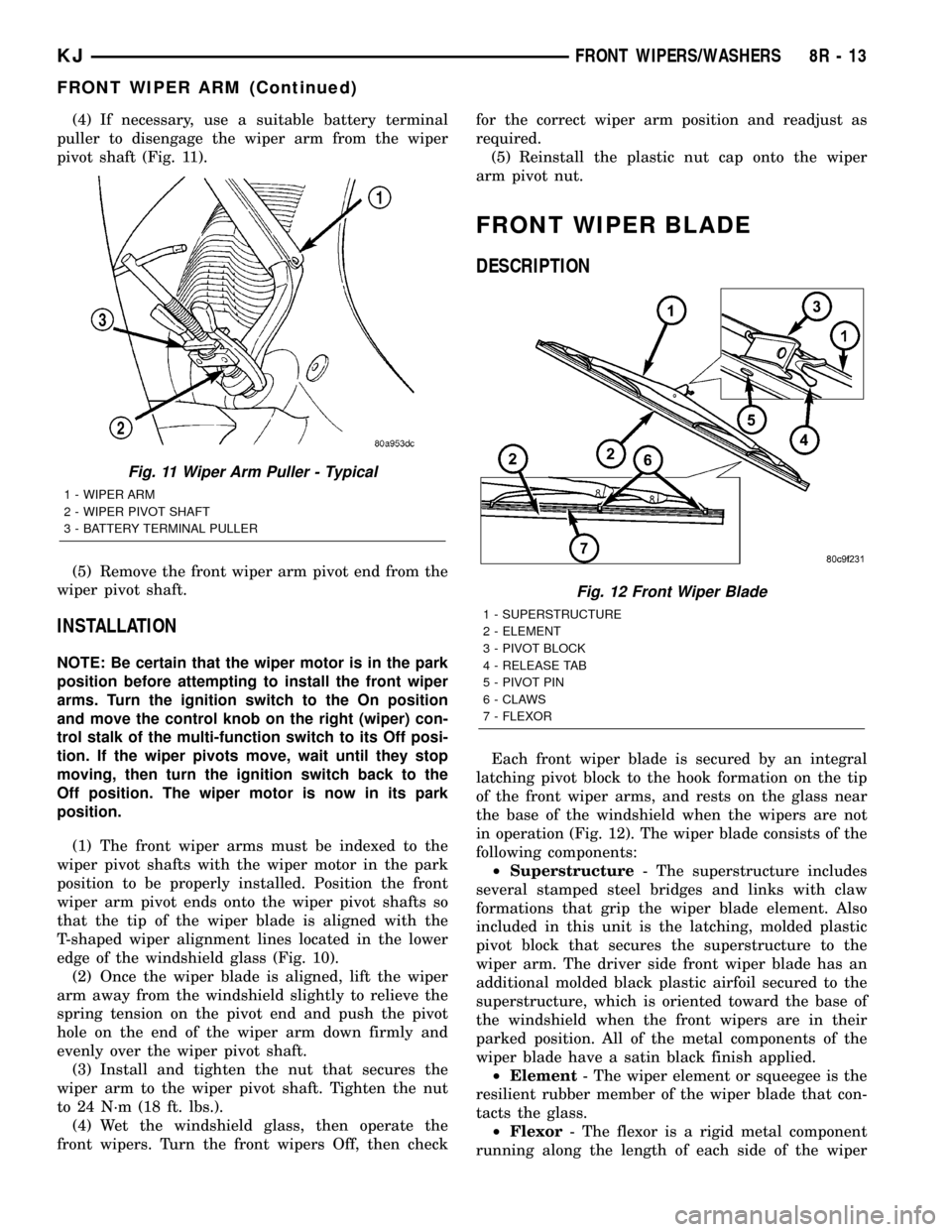
(4) If necessary, use a suitable battery terminal
puller to disengage the wiper arm from the wiper
pivot shaft (Fig. 11).
(5) Remove the front wiper arm pivot end from the
wiper pivot shaft.
INSTALLATION
NOTE: Be certain that the wiper motor is in the park
position before attempting to install the front wiper
arms. Turn the ignition switch to the On position
and move the control knob on the right (wiper) con-
trol stalk of the multi-function switch to its Off posi-
tion. If the wiper pivots move, wait until they stop
moving, then turn the ignition switch back to the
Off position. The wiper motor is now in its park
position.
(1) The front wiper arms must be indexed to the
wiper pivot shafts with the wiper motor in the park
position to be properly installed. Position the front
wiper arm pivot ends onto the wiper pivot shafts so
that the tip of the wiper blade is aligned with the
T-shaped wiper alignment lines located in the lower
edge of the windshield glass (Fig. 10).
(2) Once the wiper blade is aligned, lift the wiper
arm away from the windshield slightly to relieve the
spring tension on the pivot end and push the pivot
hole on the end of the wiper arm down firmly and
evenly over the wiper pivot shaft.
(3) Install and tighten the nut that secures the
wiper arm to the wiper pivot shaft. Tighten the nut
to 24 N´m (18 ft. lbs.).
(4) Wet the windshield glass, then operate the
front wipers. Turn the front wipers Off, then checkfor the correct wiper arm position and readjust as
required.
(5) Reinstall the plastic nut cap onto the wiper
arm pivot nut.
FRONT WIPER BLADE
DESCRIPTION
Each front wiper blade is secured by an integral
latching pivot block to the hook formation on the tip
of the front wiper arms, and rests on the glass near
the base of the windshield when the wipers are not
in operation (Fig. 12). The wiper blade consists of the
following components:
²Superstructure- The superstructure includes
several stamped steel bridges and links with claw
formations that grip the wiper blade element. Also
included in this unit is the latching, molded plastic
pivot block that secures the superstructure to the
wiper arm. The driver side front wiper blade has an
additional molded black plastic airfoil secured to the
superstructure, which is oriented toward the base of
the windshield when the front wipers are in their
parked position. All of the metal components of the
wiper blade have a satin black finish applied.
²Element- The wiper element or squeegee is the
resilient rubber member of the wiper blade that con-
tacts the glass.
²Flexor- The flexor is a rigid metal component
running along the length of each side of the wiper
Fig. 11 Wiper Arm Puller - Typical
1 - WIPER ARM
2 - WIPER PIVOT SHAFT
3 - BATTERY TERMINAL PULLER
Fig. 12 Front Wiper Blade
1 - SUPERSTRUCTURE
2 - ELEMENT
3 - PIVOT BLOCK
4 - RELEASE TAB
5 - PIVOT PIN
6 - CLAWS
7 - FLEXOR
KJFRONT WIPERS/WASHERS 8R - 13
FRONT WIPER ARM (Continued)
Page 739 of 1803
A wiper arm cannot be adjusted or repaired. If
damaged or faulty, the entire wiper arm unit must be
replaced.
OPERATION
The rear wiper arm is designed to mechanically
transmit the motion from the rear wiper motor out-
put shaft to the rear wiper blade. The wiper arm
must be properly indexed to the motor output shaft
in order to maintain the proper wiper blade travel on
the glass. The wiper arm support is designed to lift
and support the rear wiper arm and blade off of the
glass when the rear wiper blade is parked. This sup-
port and the park ramp on the tailgate outer panel
below the glass also provide an alignment reference
to ensure accurate rear wiper arm and blade instal-
lation. The tapered hole in the wiper arm pivot end
is interlocks with the serrations on the outer circum-
ference of the tapered motor output shaft, allowing
positive engagement and finite adjustment of this
connection. A hex nut secures the wiper arm pivot
end to the threads on the rear wiper motor output
shaft and the pivot cover hinges and snaps over this
connection for a neat appearance. The spring-loaded
wiper arm hinge controls the down-force applied
through the tip of the wiper arm to the wiper blade
on the glass. The hook formation on the tip of the
wiper arm provides a cradle for securing and latching
the wiper blade pivot block to the wiper arm.
REMOVAL
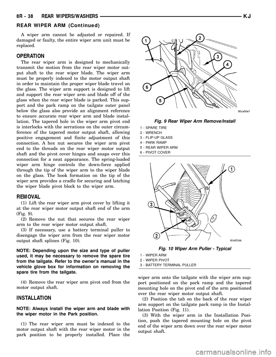
(1) Lift the rear wiper arm pivot cover by lifting it
at the rear wiper motor output shaft end of the arm
(Fig. 9).
(2) Remove the nut that secures the rear wiper
arm to the rear wiper motor output shaft.
(3) If necessary, use a battery terminal puller to
disengage the wiper arm from the rear wiper motor
output shaft splines (Fig. 10).
NOTE: Depending upon the size and type of puller
used, it may be necessary to remove the spare tire
from the tailgate. Refer to the owner's manual in the
vehicle glove box for information on removing the
spare tire from the tailgate.
(4) Remove the rear wiper arm pivot end from the
motor output shaft.
INSTALLATION
NOTE: Always install the wiper arm and blade with
the wiper motor in the Park position.
(1) The rear wiper arm must be indexed to the
motor output shaft with the rear wiper motor in the
park position to be properly installed. Place thewiper arm onto the tailgate with the wiper arm sup-
port positioned on the park ramp and the tapered
mounting hole on the pivot end of the arm positioned
over the rear wiper motor output shaft.
(2) Position the tab on the back of the rear wiper
arm support on the tailgate park ramp in the Instal-
lation Position (Fig. 11).
(3) With the wiper arm in the Installation Posi-
tion, push the tapered mounting hole on the pivot
end of the wiper arm down over the rear wiper motor
output shaft.
Fig. 9 Rear Wiper Arm Remove/Install
1 - SPARE TIRE
2 - WRENCH
3 - FLIP-UP GLASS
4 - PARK RAMP
5 - REAR WIPER ARM
6 - PIVOT COVER
Fig. 10 Wiper Arm Puller - Typical
1 - WIPER ARM
2 - WIPER PIVOT
3 - BATTERY TERMINAL PULLER
8R - 38 REAR WIPERS/WASHERSKJ
REAR WIPER ARM (Continued)
Page 746 of 1803
WIRING
TABLE OF CONTENTS
page page
WIRING DIAGRAM INFORMATION...... 8Wa-01-1
COMPONENT INDEX................. 8Wa-02-1
POWER DISTRIBUTION.............. 8Wa-10-1
JUNCTION BLOCK................... 8Wa-12-1
GROUND DISTRIBUTION............. 8Wa-15-1
BUS COMMUNICATIONS............. 8Wa-18-1
CHARGING SYSTEM................. 8Wa-20-1
STARTING SYSTEM................. 8Wa-21-1
FUEL/IGNITION SYSTEM............. 8Wa-30-1
TRANSMISSION CONTROL SYSTEM.... 8Wa-31-1
VEHICLE SPEED CONTROL........... 8Wa-33-1
ANTILOCK BRAKES.................. 8Wa-35-1
VEHICLE THEFT SECURITY SYSTEM.... 8Wa-39-1
INSTRUMENT CLUSTER.............. 8Wa-40-1
HORN/CIGAR LIGHTER/POWER OUTLET . 8Wa-41-1
AIR CONDITIONING-HEATER.......... 8Wa-42-1
AIRBAG SYSTEM................... 8Wa-43-1
INTERIOR LIGHTING................. 8Wa-44-1BODY CONTROL MODULE............ 8Wa-45-1
AUDIO SYSTEM.................... 8Wa-47-1
REAR WINDOW DEFOGGER........... 8Wa-48-1
OVERHEAD CONSOLE................ 8Wa-49-1
FRONT LIGHTING................... 8Wa-50-1
REAR LIGHTING.................... 8Wa-51-1
TURN SIGNALS..................... 8Wa-52-1
WIPERS........................... 8Wa-53-1
TRAILER TOW...................... 8Wa-54-1
POWER WINDOWS.................. 8Wa-60-1
POWER DOOR LOCKS............... 8Wa-61-1
POWER MIRRORS.................. 8Wa-62-1
POWER SEAT...................... 8Wa-63-1
POWER SUNROOF.................. 8Wa-64-1
SPLICE INFORMATION............... 8Wa-70-1
CONNECTOR PIN-OUTS.............. 8Wa-80-1
CONNECTOR/GROUND/
SPLICE LOCATION................. 8Wa-91-1 KJWIRING
8Wa-1
Page 762 of 1803
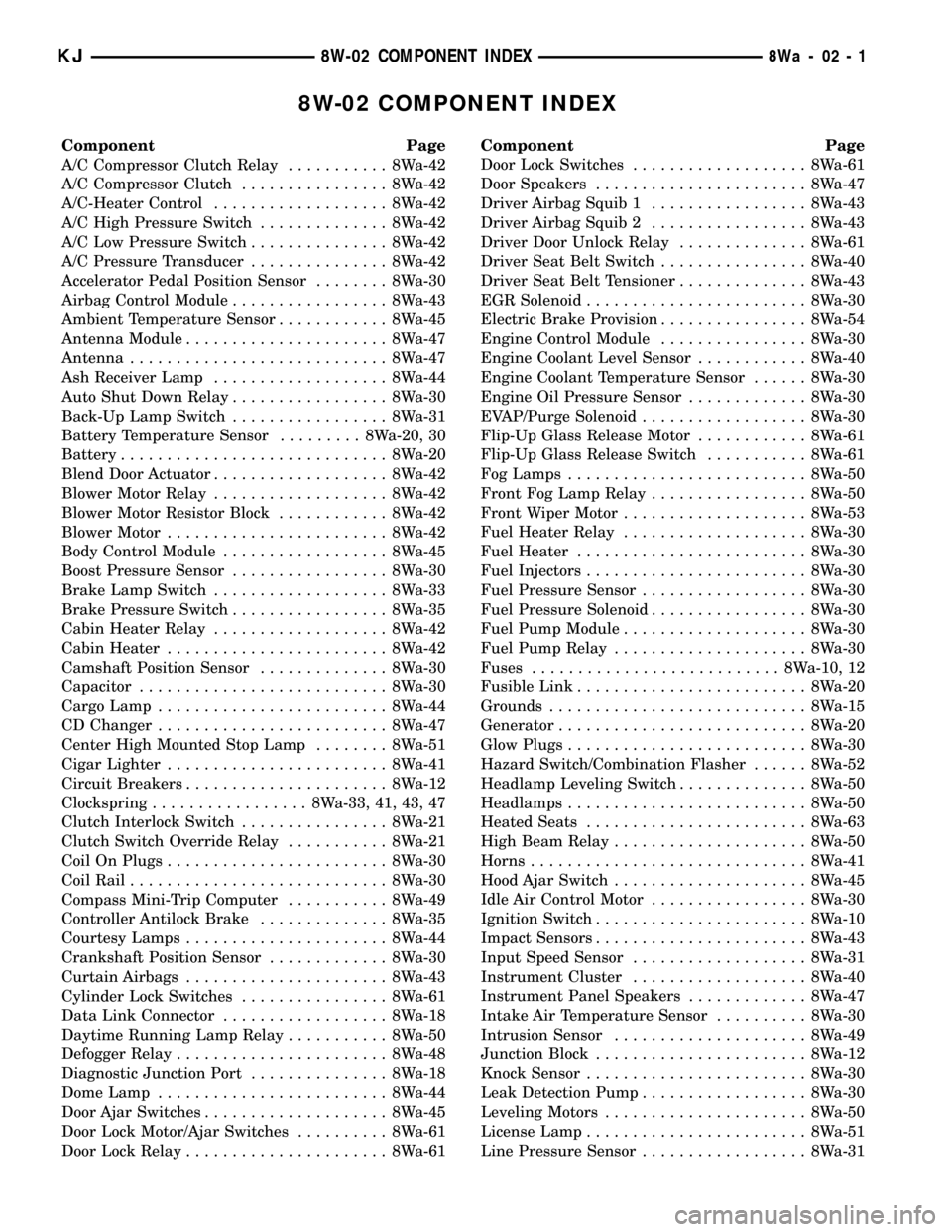
8W-02 COMPONENT INDEX
Component Page
A/C Compressor Clutch Relay........... 8Wa-42
A/C Compressor Clutch................ 8Wa-42
A/C-Heater Control................... 8Wa-42
A/C High Pressure Switch.............. 8Wa-42
A/C Low Pressure Switch............... 8Wa-42
A/C Pressure Transducer............... 8Wa-42
Accelerator Pedal Position Sensor........ 8Wa-30
Airbag Control Module................. 8Wa-43
Ambient Temperature Sensor............ 8Wa-45
Antenna Module...................... 8Wa-47
Antenna............................ 8Wa-47
Ash Receiver Lamp................... 8Wa-44
Auto Shut Down Relay................. 8Wa-30
Back-Up Lamp Switch................. 8Wa-31
Battery Temperature Sensor......... 8Wa-20, 30
Battery............................. 8Wa-20
Blend Door Actuator................... 8Wa-42
Blower Motor Relay................... 8Wa-42
Blower Motor Resistor Block............ 8Wa-42
Blower Motor........................ 8Wa-42
Body Control Module.................. 8Wa-45
Boost Pressure Sensor................. 8Wa-30
Brake Lamp Switch................... 8Wa-33
Brake Pressure Switch................. 8Wa-35
Cabin Heater Relay................... 8Wa-42
Cabin Heater........................ 8Wa-42
Camshaft Position Sensor.............. 8Wa-30
Capacitor........................... 8Wa-30
Cargo Lamp......................... 8Wa-44
CD Changer......................... 8Wa-47
Center High Mounted Stop Lamp........ 8Wa-51
Cigar Lighter........................ 8Wa-41
Circuit Breakers...................... 8Wa-12
Clockspring................. 8Wa-33, 41, 43, 47
Clutch Interlock Switch................ 8Wa-21
Clutch Switch Override Relay........... 8Wa-21
Coil On Plugs........................ 8Wa-30
Coil Rail............................ 8Wa-30
Compass Mini-Trip Computer........... 8Wa-49
Controller Antilock Brake.............. 8Wa-35
Courtesy Lamps...................... 8Wa-44
Crankshaft Position Sensor............. 8Wa-30
Curtain Airbags...................... 8Wa-43
Cylinder Lock Switches................ 8Wa-61
Data Link Connector.................. 8Wa-18
Daytime Running Lamp Relay........... 8Wa-50
Defogger Relay....................... 8Wa-48
Diagnostic Junction Port............... 8Wa-18
Dome Lamp......................... 8Wa-44
Door Ajar Switches.................... 8Wa-45
Door Lock Motor/Ajar Switches.......... 8Wa-61
Door Lock Relay...................... 8Wa-61Component Page
Door Lock Switches................... 8Wa-61
Door Speakers....................... 8Wa-47
Driver Airbag Squib 1................. 8Wa-43
Driver Airbag Squib 2................. 8Wa-43
Driver Door Unlock Relay.............. 8Wa-61
Driver Seat Belt Switch................ 8Wa-40
Driver Seat Belt Tensioner.............. 8Wa-43
EGR Solenoid........................ 8Wa-30
Electric Brake Provision................ 8Wa-54
Engine Control Module................ 8Wa-30
Engine Coolant Level Sensor............ 8Wa-40
Engine Coolant Temperature Sensor...... 8Wa-30
Engine Oil Pressure Sensor............. 8Wa-30
EVAP/Purge Solenoid.................. 8Wa-30
Flip-Up Glass Release Motor............ 8Wa-61
Flip-Up Glass Release Switch........... 8Wa-61
Fog Lamps.......................... 8Wa-50
Front Fog Lamp Relay................. 8Wa-50
Front Wiper Motor.................... 8Wa-53
Fuel Heater Relay.................... 8Wa-30
Fuel Heater......................... 8Wa-30
Fuel Injectors........................ 8Wa-30
Fuel Pressure Sensor.................. 8Wa-30
Fuel Pressure Solenoid................. 8Wa-30
Fuel Pump Module.................... 8Wa-30
Fuel Pump Relay..................... 8Wa-30
Fuses........................... 8Wa-10, 12
Fusible Link......................... 8Wa-20
Grounds............................ 8Wa-15
Generator........................... 8Wa-20
Glow Plugs.......................... 8Wa-30
Hazard Switch/Combination Flasher...... 8Wa-52
Headlamp Leveling Switch.............. 8Wa-50
Headlamps.......................... 8Wa-50
Heated Seats........................ 8Wa-63
High Beam Relay..................... 8Wa-50
Horns.............................. 8Wa-41
Hood Ajar Switch..................... 8Wa-45
Idle Air Control Motor................. 8Wa-30
Ignition Switch....................... 8Wa-10
Impact Sensors....................... 8Wa-43
Input Speed Sensor................... 8Wa-31
Instrument Cluster................... 8Wa-40
Instrument Panel Speakers............. 8Wa-47
Intake Air Temperature Sensor.......... 8Wa-30
Intrusion Sensor..................... 8Wa-49
Junction Block....................... 8Wa-12
Knock Sensor........................ 8Wa-30
Leak Detection Pump.................. 8Wa-30
Leveling Motors...................... 8Wa-50
License Lamp........................ 8Wa-51
Line Pressure Sensor.................. 8Wa-31
KJ8W-02 COMPONENT INDEX8Wa-02-1
Page 763 of 1803
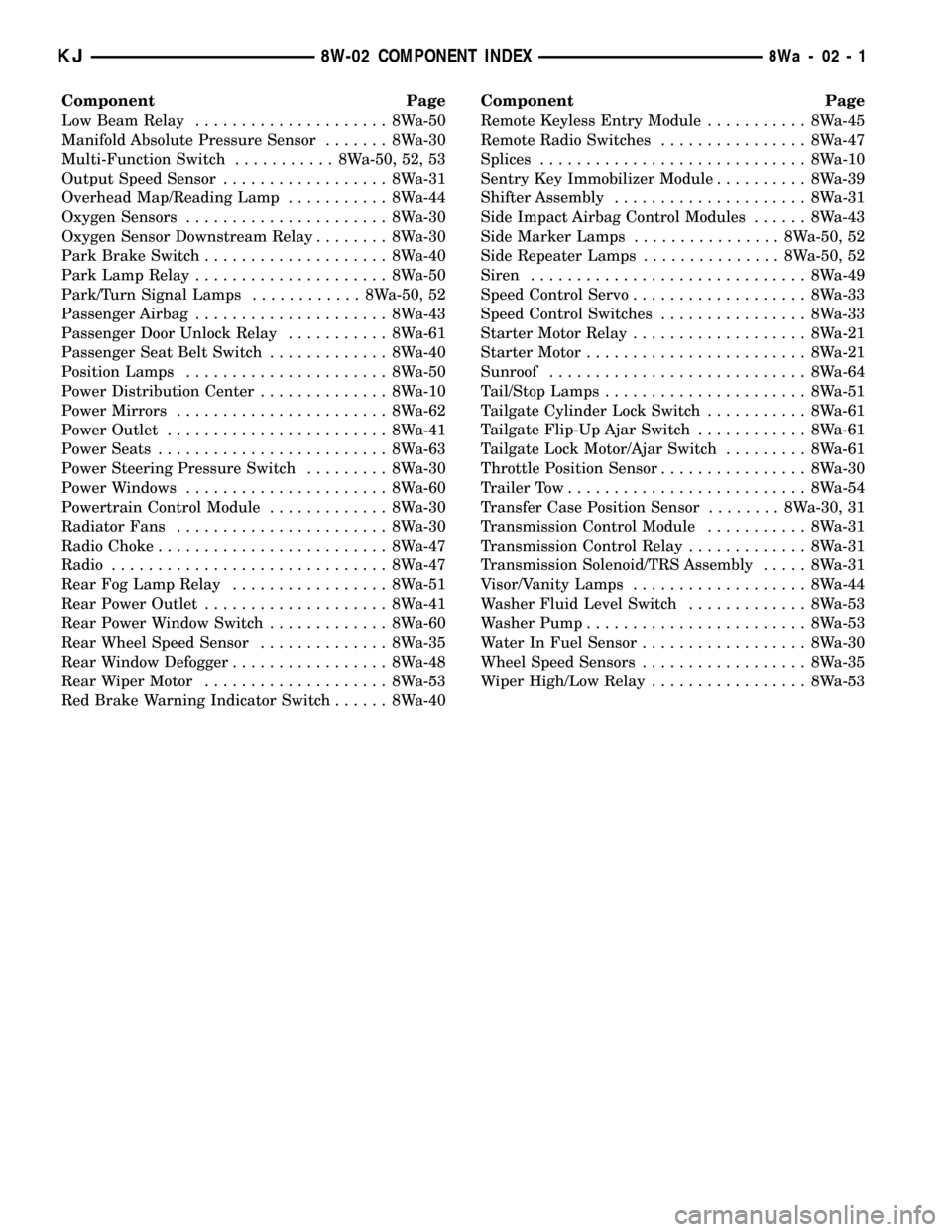
Component Page
Low Beam Relay..................... 8Wa-50
Manifold Absolute Pressure Sensor....... 8Wa-30
Multi-Function Switch........... 8Wa-50, 52, 53
Output Speed Sensor.................. 8Wa-31
Overhead Map/Reading Lamp........... 8Wa-44
Oxygen Sensors...................... 8Wa-30
Oxygen Sensor Downstream Relay........ 8Wa-30
Park Brake Switch.................... 8Wa-40
Park Lamp Relay..................... 8Wa-50
Park/Turn Signal Lamps............ 8Wa-50, 52
Passenger Airbag..................... 8Wa-43
Passenger Door Unlock Relay........... 8Wa-61
Passenger Seat Belt Switch............. 8Wa-40
Position Lamps...................... 8Wa-50
Power Distribution Center.............. 8Wa-10
Power Mirrors....................... 8Wa-62
Power Outlet........................ 8Wa-41
Power Seats......................... 8Wa-63
Power Steering Pressure Switch......... 8Wa-30
Power Windows...................... 8Wa-60
Powertrain Control Module............. 8Wa-30
Radiator Fans....................... 8Wa-30
Radio Choke......................... 8Wa-47
Radio.............................. 8Wa-47
Rear Fog Lamp Relay................. 8Wa-51
Rear Power Outlet.................... 8Wa-41
Rear Power Window Switch............. 8Wa-60
Rear Wheel Speed Sensor.............. 8Wa-35
Rear Window Defogger................. 8Wa-48
Rear Wiper Motor.................... 8Wa-53
Red Brake Warning Indicator Switch...... 8Wa-40Component Page
Remote Keyless Entry Module........... 8Wa-45
Remote Radio Switches................ 8Wa-47
Splices............................. 8Wa-10
Sentry Key Immobilizer Module.......... 8Wa-39
Shifter Assembly..................... 8Wa-31
Side Impact Airbag Control Modules...... 8Wa-43
Side Marker Lamps................ 8Wa-50, 52
Side Repeater Lamps............... 8Wa-50, 52
Siren.............................. 8Wa-49
Speed Control Servo................... 8Wa-33
Speed Control Switches................ 8Wa-33
Starter Motor Relay................... 8Wa-21
Starter Motor........................ 8Wa-21
Sunroof............................ 8Wa-64
Tail/Stop Lamps...................... 8Wa-51
Tailgate Cylinder Lock Switch........... 8Wa-61
Tailgate Flip-Up Ajar Switch............ 8Wa-61
Tailgate Lock Motor/Ajar Switch......... 8Wa-61
Throttle Position Sensor................ 8Wa-30
Trailer Tow.......................... 8Wa-54
Transfer Case Position Sensor........ 8Wa-30, 31
Transmission Control Module........... 8Wa-31
Transmission Control Relay............. 8Wa-31
Transmission Solenoid/TRS Assembly..... 8Wa-31
Visor/Vanity Lamps................... 8Wa-44
Washer Fluid Level Switch............. 8Wa-53
Washer Pump........................ 8Wa-53
Water In Fuel Sensor.................. 8Wa-30
Wheel Speed Sensors.................. 8Wa-35
Wiper High/Low Relay................. 8Wa-53
KJ8W-02 COMPONENT INDEX8Wa-02-1
Page 1156 of 1803
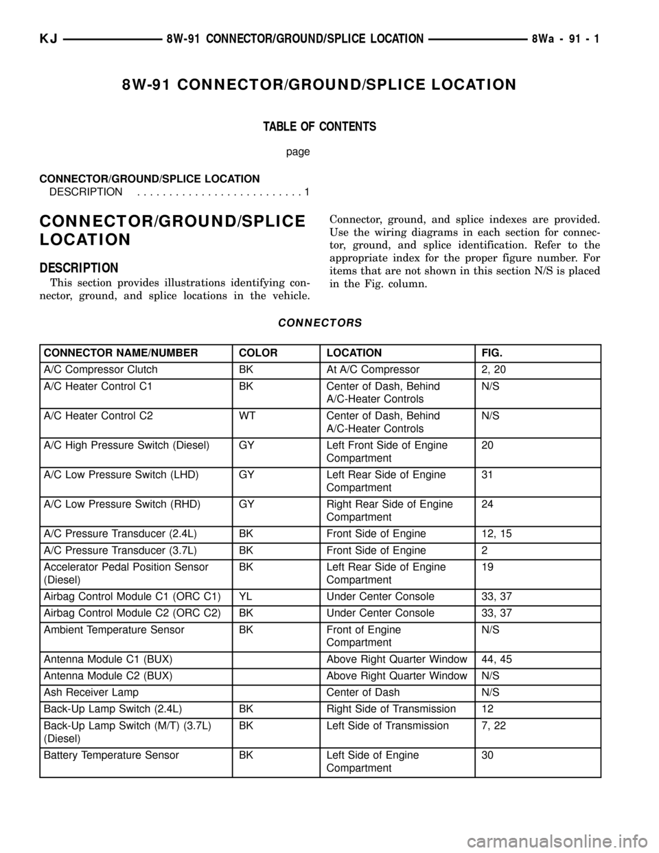
8W-91 CONNECTOR/GROUND/SPLICE LOCATION
TABLE OF CONTENTS
page
CONNECTOR/GROUND/SPLICE LOCATION
DESCRIPTION..........................1
CONNECTOR/GROUND/SPLICE
LOCATION
DESCRIPTION
This section provides illustrations identifying con-
nector, ground, and splice locations in the vehicle.Connector, ground, and splice indexes are provided.
Use the wiring diagrams in each section for connec-
tor, ground, and splice identification. Refer to the
appropriate index for the proper figure number. For
items that are not shown in this section N/S is placed
in the Fig. column.
CONNECTORS
CONNECTOR NAME/NUMBER COLOR LOCATION FIG.
A/C Compressor Clutch BK At A/C Compressor 2, 20
A/C Heater Control C1 BK Center of Dash, Behind
A/C-Heater ControlsN/S
A/C Heater Control C2 WT Center of Dash, Behind
A/C-Heater ControlsN/S
A/C High Pressure Switch (Diesel) GY Left Front Side of Engine
Compartment20
A/C Low Pressure Switch (LHD) GY Left Rear Side of Engine
Compartment31
A/C Low Pressure Switch (RHD) GY Right Rear Side of Engine
Compartment24
A/C Pressure Transducer (2.4L) BK Front Side of Engine 12, 15
A/C Pressure Transducer (3.7L) BK Front Side of Engine 2
Accelerator Pedal Position Sensor
(Diesel)BK Left Rear Side of Engine
Compartment19
Airbag Control Module C1 (ORC C1) YL Under Center Console 33, 37
Airbag Control Module C2 (ORC C2) BK Under Center Console 33, 37
Ambient Temperature Sensor BK Front of Engine
CompartmentN/S
Antenna Module C1 (BUX) Above Right Quarter Window 44, 45
Antenna Module C2 (BUX) Above Right Quarter Window N/S
Ash Receiver Lamp Center of Dash N/S
Back-Up Lamp Switch (2.4L) BK Right Side of Transmission 12
Back-Up Lamp Switch (M/T) (3.7L)
(Diesel)BK Left Side of Transmission 7, 22
Battery Temperature Sensor BK Left Side of Engine
Compartment30
KJ8W-91 CONNECTOR/GROUND/SPLICE LOCATION8Wa-91-1
Page 1287 of 1803
(2) To determine if the secondary timing chains
are worn, rotate the engine clockwise until maximum
tensioner piston extension is obtained. Measure the
distance between the secondary timing chain ten-
sioner housing and the step ledge on the piston. The
measurement at point (A) must be less than 15mm
(.5906 inches).
(3) If the measurement exceeds the specification
the secondary timing chains are worn and require
replacement. Refer to Timing Chain and Sprockets in
this section for procedure.
SERVICE PROCEDURES
TIMING VERIFICATION
CAUTION: The 3.7L is a non free-wheeling design
engine. Therefore, correct engine timing is critical.
NOTE: Components referred to as left hand or right
hand are as viewed from the drivers position inside
the vehicle.
NOTE: The blue link plates on the chains and the
dots on the camshaft drive sprockets may not line
up during the timing verification procedure. The
blue link plates are lined up with the sprocket dots
only when re-timing the complete timing drive.
Once the timing drive is rotated blue link-to-dot
alignment is no longer valid.
Engine base timing can be verified by the following
procedure:
(1) Remove the cylinder head covers. Refer to the
procedure in this section.
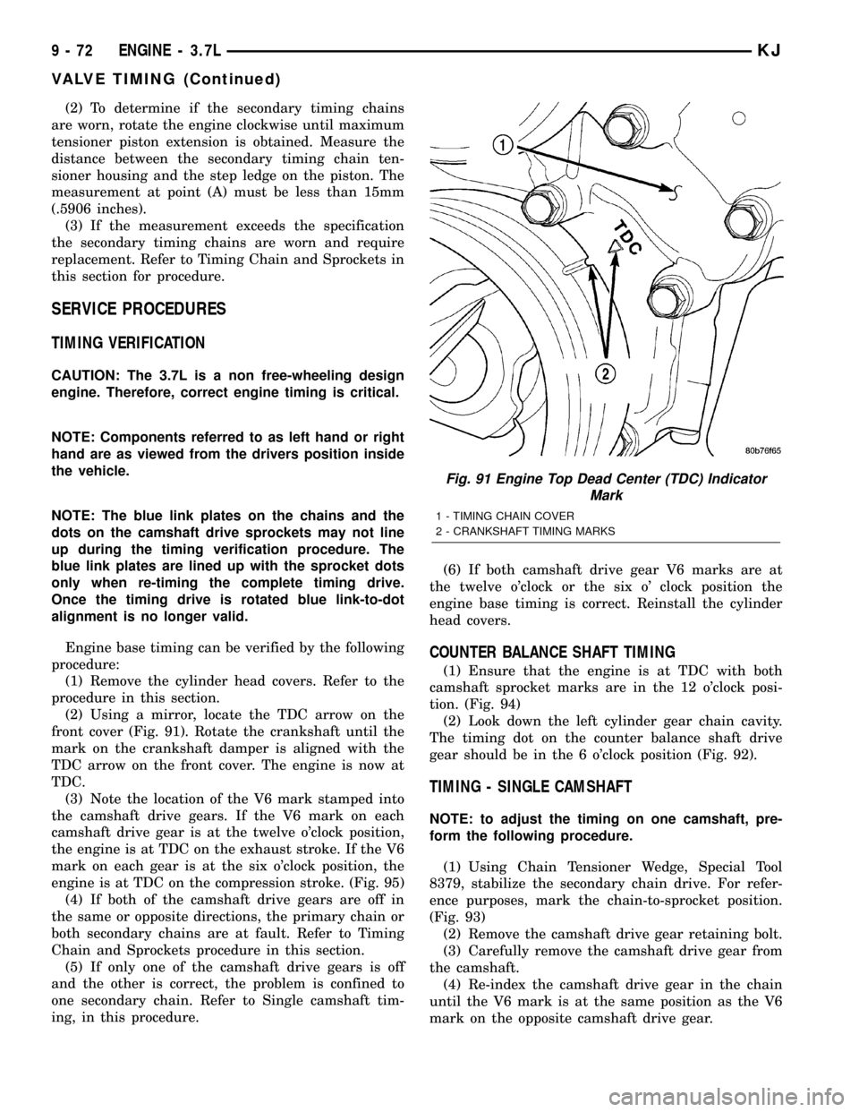
(2) Using a mirror, locate the TDC arrow on the
front cover (Fig. 91). Rotate the crankshaft until the
mark on the crankshaft damper is aligned with the
TDC arrow on the front cover. The engine is now at
TDC.
(3) Note the location of the V6 mark stamped into
the camshaft drive gears. If the V6 mark on each
camshaft drive gear is at the twelve o'clock position,
the engine is at TDC on the exhaust stroke. If the V6
mark on each gear is at the six o'clock position, the
engine is at TDC on the compression stroke. (Fig. 95)
(4) If both of the camshaft drive gears are off in
the same or opposite directions, the primary chain or
both secondary chains are at fault. Refer to Timing
Chain and Sprockets procedure in this section.
(5) If only one of the camshaft drive gears is off
and the other is correct, the problem is confined to
one secondary chain. Refer to Single camshaft tim-
ing, in this procedure.(6) If both camshaft drive gear V6 marks are at
the twelve o'clock or the six o' clock position the
engine base timing is correct. Reinstall the cylinder
head covers.
COUNTER BALANCE SHAFT TIMING
(1) Ensure that the engine is at TDC with both
camshaft sprocket marks are in the 12 o'clock posi-
tion. (Fig. 94)
(2) Look down the left cylinder gear chain cavity.
The timing dot on the counter balance shaft drive
gear should be in the 6 o'clock position (Fig. 92).
TIMING - SINGLE CAMSHAFT
NOTE: to adjust the timing on one camshaft, pre-
form the following procedure.
(1) Using Chain Tensioner Wedge, Special Tool
8379, stabilize the secondary chain drive. For refer-
ence purposes, mark the chain-to-sprocket position.
(Fig. 93)
(2) Remove the camshaft drive gear retaining bolt.
(3) Carefully remove the camshaft drive gear from
the camshaft.
(4) Re-index the camshaft drive gear in the chain
until the V6 mark is at the same position as the V6
mark on the opposite camshaft drive gear.
Fig. 91 Engine Top Dead Center (TDC) Indicator
Mark
1 - TIMING CHAIN COVER
2 - CRANKSHAFT TIMING MARKS
9 - 72 ENGINE - 3.7LKJ
VALVE TIMING (Continued)
Page 1409 of 1803
(14) Continue lowering tank while guiding remain-
ing hoses and lines.
(15) If fuel tank is to be replaced, remove LDP,
fuel filter and fuel pump module from tank. Refer to
Leak Detection Pump, Fuel Filter and Fuel Pump
Module Removal/Installation procedures.
INSTALLATION
(1) If fuel tank is to be replaced, install LDP, fuel
filter and fuel pump module to tank. Refer to Leak
Detection Pump, Fuel Filter and Fuel Pump Module
Removal/Installation procedures.
(2) Position fuel tank to hydraulic jack.
(3) Raise tank while carefully guiding vent tubes/
hoses through frame rail and crossmember. Before
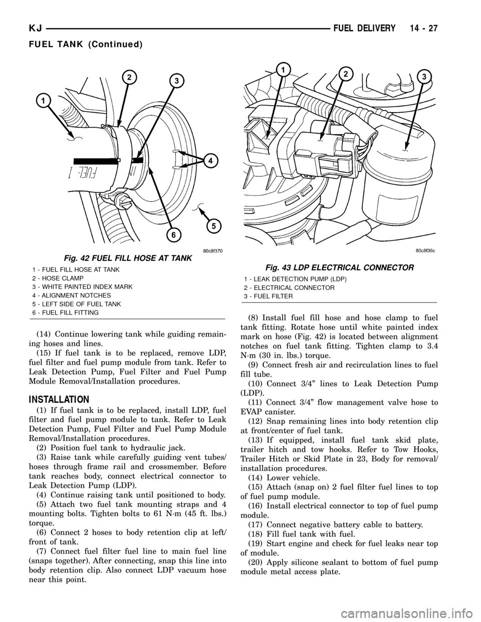
tank reaches body, connect electrical connector to
Leak Detection Pump (LDP).
(4) Continue raising tank until positioned to body.
(5) Attach two fuel tank mounting straps and 4
mounting bolts. Tighten bolts to 61 N´m (45 ft. lbs.)
torque.
(6) Connect 2 hoses to body retention clip at left/
front of tank.
(7) Connect fuel filter fuel line to main fuel line
(snaps together). After connecting, snap this line into
body retention clip. Also connect LDP vacuum hose
near this point.(8) Install fuel fill hose and hose clamp to fuel
tank fitting. Rotate hose until white painted index
mark on hose (Fig. 42) is located between alignment
notches on fuel tank fitting. Tighten clamp to 3.4
N´m (30 in. lbs.) torque.
(9) Connect fresh air and recirculation lines to fuel
fill tube.
(10) Connect 3/4º lines to Leak Detection Pump
(LDP).
(11) Connect 3/4º flow management valve hose to
EVAP canister.
(12) Snap remaining lines into body retention clip
at front/center of fuel tank.
(13) If equipped, install fuel tank skid plate,
trailer hitch and tow hooks. Refer to Tow Hooks,
Trailer Hitch or Skid Plate in 23, Body for removal/
installation procedures.
(14) Lower vehicle.
(15) Attach (snap on) 2 fuel filter fuel lines to top
of fuel pump module.
(16) Install electrical connector to top of fuel pump
module.
(17) Connect negative battery cable to battery.
(18) Fill fuel tank with fuel.
(19) Start engine and check for fuel leaks near top
of module.
(20) Apply silicone sealant to bottom of fuel pump
module metal access plate.
Fig. 42 FUEL FILL HOSE AT TANK
1 - FUEL FILL HOSE AT TANK
2 - HOSE CLAMP
3 - WHITE PAINTED INDEX MARK
4 - ALIGNMENT NOTCHES
5 - LEFT SIDE OF FUEL TANK
6 - FUEL FILL FITTINGFig. 43 LDP ELECTRICAL CONNECTOR
1 - LEAK DETECTION PUMP (LDP)
2 - ELECTRICAL CONNECTOR
3 - FUEL FILTER
KJFUEL DELIVERY 14 - 27
FUEL TANK (Continued)
Page 1471 of 1803
BODY STRUCTURE
TABLE OF CONTENTS
page page
ASSEMBLY
SPECIFICATIONS
SPECIFICATION.......................6
WELD AND STRUCTURAL ADHESIVE
LOCATIONS
SPECIFICATIONS........................9SEALER LOCATIONS
SPECIFICATIONS.......................87
OPENING DIMENSIONS
SPECIFICATIONS......................111
GAP AND FLUSH
SPECIFICATIONS......................116
ASSEMBLY
SPECIFICATIONS
SPECIFICATION
INDEX
DESCRIPTION FIGURE
COMPLETE BODY STRUCTURE VIEWS ( 1 )
BODY STRUCTURE - SECTIONS ( 2 )
23 - 6 BODY STRUCTUREKJ