Index JEEP LIBERTY 2002 KJ / 1.G Workshop Manual
[x] Cancel search | Manufacturer: JEEP, Model Year: 2002, Model line: LIBERTY, Model: JEEP LIBERTY 2002 KJ / 1.GPages: 1803, PDF Size: 62.3 MB
Page 2 of 1803
FOREWORD
This manual is designed as a supplement to be used along with the 2002 Liberty service manual,
81-370-02060. It includes information related to the 2.4L gas engine installed in this vehicle by
DaimlerChrysler Corporation. For diagnosis or service procedures relating to other components or systems,
refer to the 2002 Liberty Service Manual.
The information contained in this service manual has been prepared for the professional automotive tech-
nician involved in daily repair operations. Information describing the operation and use of standard and
optional equipment is included in the Owner's Manual provided with the vehicle.
Information in this manual is divided into groups. These groups contain description, operation, diagnosis,
testing, adjustments, removal, installation, disassembly, and assembly procedures for the systems and compo-
nents. To assist in locating a group title page, use the Group Tab Locator on the following page. The solid bar
after the group title is aligned to a solid tab on the first page of each group. The first page of the group has
a contents section that lists major topics within the group. If you are not sure which Group contains the infor-
mation you need, look up the Component/System in the alphabetical index located in the rear of this manual.
A Service Manual Comment form is included at the rear of this manual. Use the form to provide
DaimlerChrysler Corporation with your comments and suggestions.
Tightening torques are provided as a specific value throughout this manual. This value represents the
midpoint of the acceptable engineering torque range for a given fastener application. These torque values are
intended for use in service assembly and installation procedures using the correct OEM fasteners. When
replacing fasteners, always use the same type (part number) fastener as removed.
DaimlerChrysler Corporation reserves the right to change testing procedures, specifications, diagnosis,
repair methods, or vehicle wiring at any time without prior notice or incurring obligation.
Page 3 of 1803
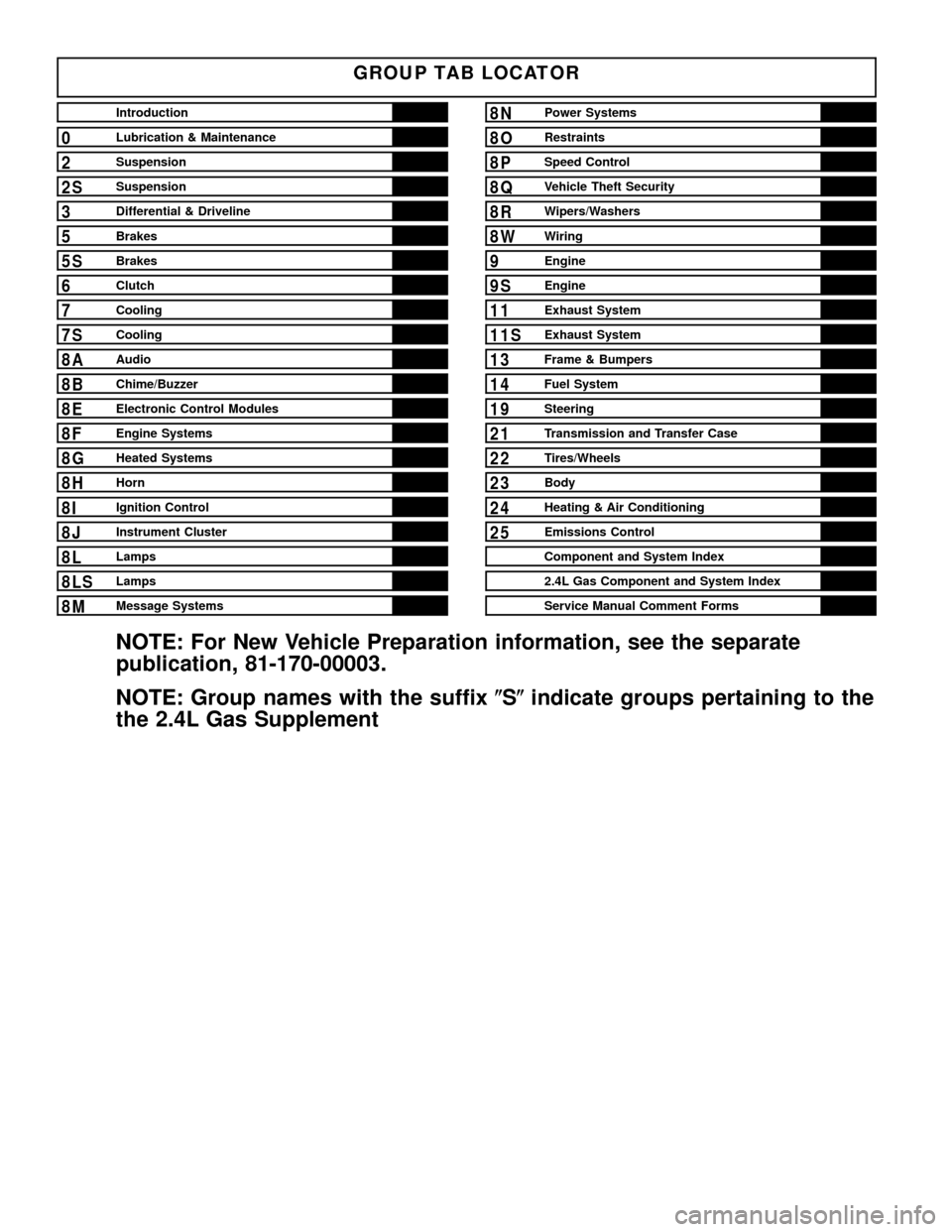
GROUP TAB LOCATOR
Introduction
0Lubrication & Maintenance
2Suspension
2SSuspension
3Differential & Driveline
5Brakes
5SBrakes
6Clutch
7Cooling
7SCooling
8AAudio
8BChime/Buzzer
8EElectronic Control Modules
8FEngine Systems
8GHeated Systems
8HHorn
8IIgnition Control
8JInstrument Cluster
8LLamps
8LSLamps
8MMessage Systems
8NPower Systems
8ORestraints
8PSpeed Control
8QVehicle Theft Security
8RWipers/Washers
8WWiring
9Engine
9SEngine
11Exhaust System
11SExhaust System
13Frame & Bumpers
14Fuel System
19Steering
21Transmission and Transfer Case
22Tires/Wheels
23Body
24Heating & Air Conditioning
25Emissions Control
Component and System Index
2.4L Gas Component and System Index
Service Manual Comment Forms
NOTE: For New Vehicle Preparation information, see the separate
publication, 81-170-00003.
NOTE: Group names with the suffix(S(indicate groups pertaining to the
the 2.4L Gas Supplement
Page 51 of 1803
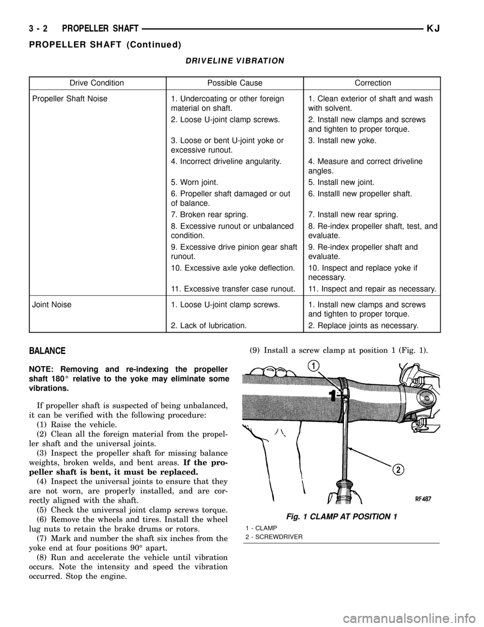
DRIVELINE VIBRATION
Drive Condition Possible Cause Correction
Propeller Shaft Noise 1. Undercoating or other foreign
material on shaft.1. Clean exterior of shaft and wash
with solvent.
2. Loose U-joint clamp screws. 2. Install new clamps and screws
and tighten to proper torque.
3. Loose or bent U-joint yoke or
excessive runout.3. Install new yoke.
4. Incorrect driveline angularity. 4. Measure and correct driveline
angles.
5. Worn joint. 5. Install new joint.
6. Propeller shaft damaged or out
of balance.6. Installl new propeller shaft.
7. Broken rear spring. 7. Install new rear spring.
8. Excessive runout or unbalanced
condition.8. Re-index propeller shaft, test, and
evaluate.
9. Excessive drive pinion gear shaft
runout.9. Re-index propeller shaft and
evaluate.
10. Excessive axle yoke deflection. 10. Inspect and replace yoke if
necessary.
11. Excessive transfer case runout. 11. Inspect and repair as necessary.
Joint Noise 1. Loose U-joint clamp screws. 1. Install new clamps and screws
and tighten to proper torque.
2. Lack of lubrication. 2. Replace joints as necessary.
BALANCE
NOTE: Removing and re-indexing the propeller
shaft 180É relative to the yoke may eliminate some
vibrations.
If propeller shaft is suspected of being unbalanced,
it can be verified with the following procedure:
(1) Raise the vehicle.
(2) Clean all the foreign material from the propel-
ler shaft and the universal joints.
(3) Inspect the propeller shaft for missing balance
weights, broken welds, and bent areas.If the pro-
peller shaft is bent, it must be replaced.
(4) Inspect the universal joints to ensure that they
are not worn, are properly installed, and are cor-
rectly aligned with the shaft.
(5) Check the universal joint clamp screws torque.
(6) Remove the wheels and tires. Install the wheel
lug nuts to retain the brake drums or rotors.
(7) Mark and number the shaft six inches from the
yoke end at four positions 90É apart.
(8) Run and accelerate the vehicle until vibration
occurs. Note the intensity and speed the vibration
occurred. Stop the engine.(9) Install a screw clamp at position 1 (Fig. 1).
Fig. 1 CLAMP AT POSITION 1
1 - CLAMP
2 - SCREWDRIVER
3 - 2 PROPELLER SHAFTKJ
PROPELLER SHAFT (Continued)
Page 52 of 1803
(10) Start the engine and re-check for vibration. If
there is little or no change in vibration, move the
clamp to one of the other three positions. Repeat the
vibration test.
(11) If there is no difference in vibration at the
other positions, the source of the vibration may not
be propeller shaft.
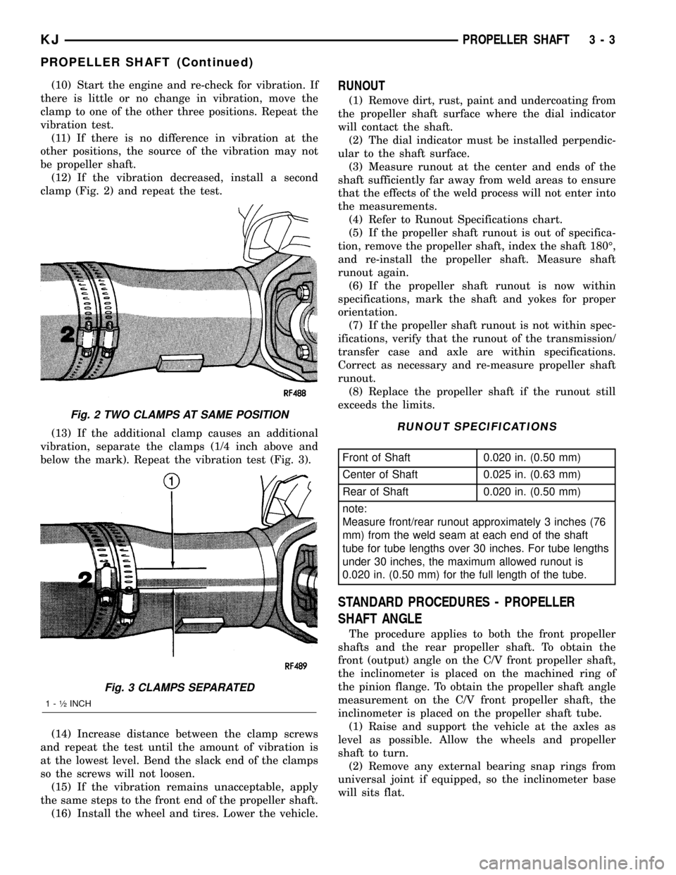
(12) If the vibration decreased, install a second
clamp (Fig. 2) and repeat the test.
(13) If the additional clamp causes an additional
vibration, separate the clamps (1/4 inch above and
below the mark). Repeat the vibration test (Fig. 3).
(14) Increase distance between the clamp screws
and repeat the test until the amount of vibration is
at the lowest level. Bend the slack end of the clamps
so the screws will not loosen.
(15) If the vibration remains unacceptable, apply
the same steps to the front end of the propeller shaft.
(16) Install the wheel and tires. Lower the vehicle.RUNOUT
(1) Remove dirt, rust, paint and undercoating from
the propeller shaft surface where the dial indicator
will contact the shaft.
(2) The dial indicator must be installed perpendic-
ular to the shaft surface.
(3) Measure runout at the center and ends of the
shaft sufficiently far away from weld areas to ensure
that the effects of the weld process will not enter into
the measurements.
(4) Refer to Runout Specifications chart.
(5) If the propeller shaft runout is out of specifica-
tion, remove the propeller shaft, index the shaft 180É,
and re-install the propeller shaft. Measure shaft
runout again.
(6) If the propeller shaft runout is now within
specifications, mark the shaft and yokes for proper
orientation.
(7) If the propeller shaft runout is not within spec-
ifications, verify that the runout of the transmission/
transfer case and axle are within specifications.
Correct as necessary and re-measure propeller shaft
runout.
(8) Replace the propeller shaft if the runout still
exceeds the limits.
RUNOUT SPECIFICATIONS
Front of Shaft 0.020 in. (0.50 mm)
Center of Shaft 0.025 in. (0.63 mm)
Rear of Shaft 0.020 in. (0.50 mm)
note:
Measure front/rear runout approximately 3 inches (76
mm) from the weld seam at each end of the shaft
tube for tube lengths over 30 inches. For tube lengths
under 30 inches, the maximum allowed runout is
0.020 in. (0.50 mm) for the full length of the tube.
STANDARD PROCEDURES - PROPELLER
SHAFT ANGLE
The procedure applies to both the front propeller
shafts and the rear propeller shaft. To obtain the
front (output) angle on the C/V front propeller shaft,
the inclinometer is placed on the machined ring of
the pinion flange. To obtain the propeller shaft angle
measurement on the C/V front propeller shaft, the
inclinometer is placed on the propeller shaft tube.
(1) Raise and support the vehicle at the axles as
level as possible. Allow the wheels and propeller
shaft to turn.
(2) Remove any external bearing snap rings from
universal joint if equipped, so the inclinometer base
will sits flat.
Fig. 2 TWO CLAMPS AT SAME POSITION
Fig. 3 CLAMPS SEPARATED
1 - ó INCH
KJPROPELLER SHAFT 3 - 3
PROPELLER SHAFT (Continued)
Page 232 of 1803
CONDITION POSSIBLE CAUSES CORRECTION
BELT BROKEN (NOTE: IDENTIFY
AND CORRECT PROBLEM
BEFORE NEW BELT IS
INSTALLED)1. Excessive tension. 1. Replace belt and automatic belt
tensioner.
2. Incorrect belt. 2. Replace belt.
3. Tensile member damaged during
belt installation.3. Replace belt.
4. Severe misalignment. 4. Check and replace.
5. Bracket, pulley, or bearing failure. 5. Replace defective component
and belt.
NOISE (OBJECTIONABLE
SQUEAL, SQUEAK, OR RUMBLE
IS HEARD OR FELT WHILE
DRIVE BELT IS IN OPERATION)1. Belt slippage. 1. Replace belt or automatic belt
tensioner.
2. Bearing noise. 2. Locate and repair.
3. Belt misalignment. 3. Replace belt.
4. Belt-to-pulley mismatch. 4. Install correct belt.
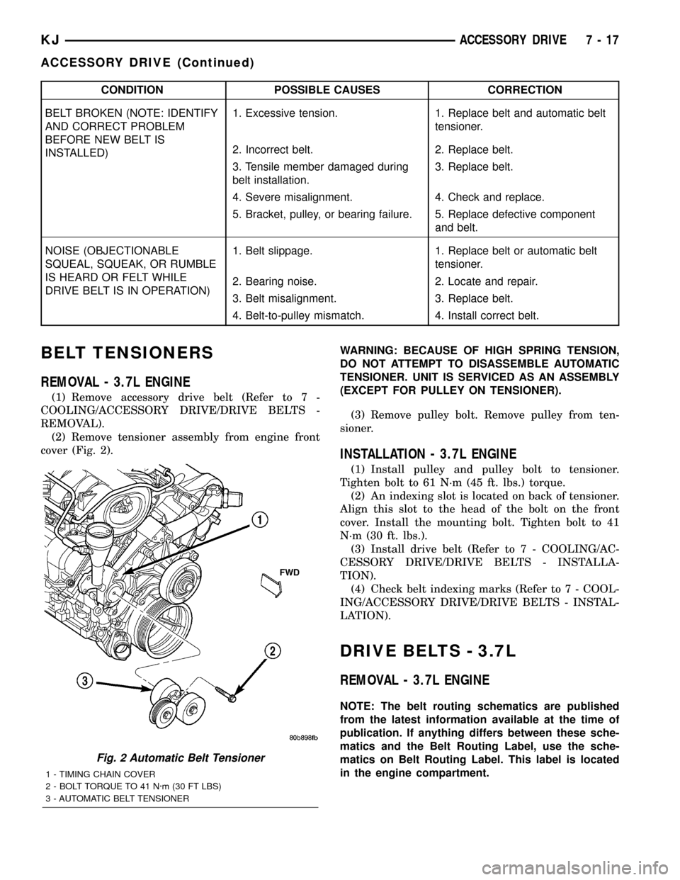
BELT TENSIONERS
REMOVAL - 3.7L ENGINE
(1) Remove accessory drive belt (Refer to 7 -
COOLING/ACCESSORY DRIVE/DRIVE BELTS -
REMOVAL).
(2) Remove tensioner assembly from engine front
cover (Fig. 2).WARNING: BECAUSE OF HIGH SPRING TENSION,
DO NOT ATTEMPT TO DISASSEMBLE AUTOMATIC
TENSIONER. UNIT IS SERVICED AS AN ASSEMBLY
(EXCEPT FOR PULLEY ON TENSIONER).
(3) Remove pulley bolt. Remove pulley from ten-
sioner.
INSTALLATION - 3.7L ENGINE
(1) Install pulley and pulley bolt to tensioner.
Tighten bolt to 61 N´m (45 ft. lbs.) torque.
(2) An indexing slot is located on back of tensioner.
Align this slot to the head of the bolt on the front
cover. Install the mounting bolt. Tighten bolt to 41
N´m (30 ft. lbs.).
(3) Install drive belt (Refer to 7 - COOLING/AC-
CESSORY DRIVE/DRIVE BELTS - INSTALLA-
TION).
(4) Check belt indexing marks (Refer to 7 - COOL-
ING/ACCESSORY DRIVE/DRIVE BELTS - INSTAL-
LATION).
DRIVE BELTS - 3.7L
REMOVAL - 3.7L ENGINE
NOTE: The belt routing schematics are published
from the latest information available at the time of
publication. If anything differs between these sche-
matics and the Belt Routing Label, use the sche-
matics on Belt Routing Label. This label is located
in the engine compartment.
Fig. 2 Automatic Belt Tensioner
1 - TIMING CHAIN COVER
2 - BOLT TORQUE TO 41 N´m (30 FT LBS)
3 - AUTOMATIC BELT TENSIONER
KJACCESSORY DRIVE 7 - 17
ACCESSORY DRIVE (Continued)
Page 261 of 1803
ACCESSORY DRIVE
TABLE OF CONTENTS
page page
BELT TENSIONERS - 2.4L
REMOVAL - 2.4L ENGINE.................14
INSTALLATION - 2.4L ENGINE.............14
DRIVE BELTS -2.4L
DIAGNOSIS AND TESTING - SERPENTINE
DRIVE BELT DIAGNOSIS................15REMOVAL - 2.4L ENGINE.................16
INSTALLATION - 2.4L ENGINE.............17
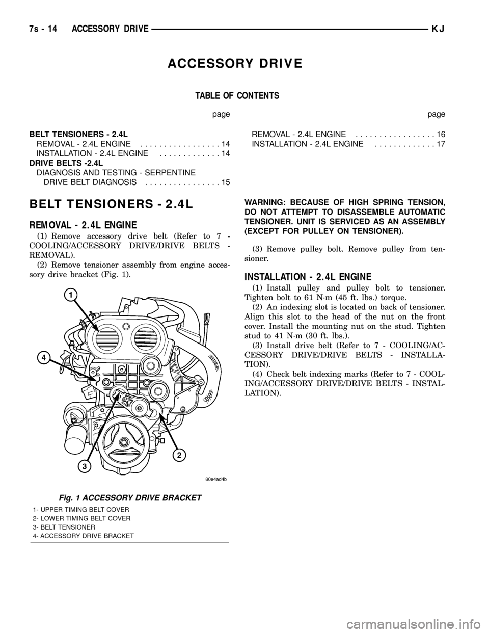
BELT TENSIONERS - 2.4L
REMOVAL - 2.4L ENGINE
(1) Remove accessory drive belt (Refer to 7 -
COOLING/ACCESSORY DRIVE/DRIVE BELTS -
REMOVAL).
(2) Remove tensioner assembly from engine acces-
sory drive bracket (Fig. 1).WARNING: BECAUSE OF HIGH SPRING TENSION,
DO NOT ATTEMPT TO DISASSEMBLE AUTOMATIC
TENSIONER. UNIT IS SERVICED AS AN ASSEMBLY
(EXCEPT FOR PULLEY ON TENSIONER).
(3) Remove pulley bolt. Remove pulley from ten-
sioner.
INSTALLATION - 2.4L ENGINE
(1) Install pulley and pulley bolt to tensioner.
Tighten bolt to 61 N´m (45 ft. lbs.) torque.
(2) An indexing slot is located on back of tensioner.
Align this slot to the head of the nut on the front
cover. Install the mounting nut on the stud. Tighten
stud to 41 N´m (30 ft. lbs.).
(3) Install drive belt (Refer to 7 - COOLING/AC-
CESSORY DRIVE/DRIVE BELTS - INSTALLA-
TION).
(4) Check belt indexing marks (Refer to 7 - COOL-
ING/ACCESSORY DRIVE/DRIVE BELTS - INSTAL-
LATION).
Fig. 1 ACCESSORY DRIVE BRACKET
1- UPPER TIMING BELT COVER
2- LOWER TIMING BELT COVER
3- BELT TENSIONER
4- ACCESSORY DRIVE BRACKET
7s - 14 ACCESSORY DRIVEKJ
Page 267 of 1803
Propylene-glycol/ethylene-glycol Mixtures can
cause the destabilization of various corrosion inhibi-
tors, causing damage to the various cooling system
components. Also, once ethylene-glycol and propy-
lene-glycol based coolants are mixed in the vehicle,
conventional methods of determining freeze point will
not be accurate. Both the refractive index and spe-
cific gravity differ between ethylene glycol and propy-
lene glycol.
OPERATION
Coolant flows through the engine block absorbing
the heat from the engine, then flows to the radiator
where the cooling fins in the radiator transfers the
heat from the coolant to the atmosphere. During cold
weather the ethylene-glycol coolant prevents water
present in the cooling system from freezing within
temperatures indicated by mixture ratio of coolant to
water.
COOLANT RECOVERY PRESS
CONTAINER
DESCRIPTION
This system works along with the radiator pres-
sure cap. This is done by using thermal expansion
and contraction of the coolant to keep the coolant
free of trapped air. It provides:
²A volume for coolant expansion and contraction.
²A convenient and safe method for checking/ad-
justing coolant level at atmospheric pressure. This is
done without removing the radiator pressure cap.
²Some reserve coolant to the radiator to cover
minor leaks and evaporation or boiling losses.
As the engine cools, a vacuum is formed in the
cooling system of both the radiator and engine. Cool-
ant will then be drawn from the coolant tank and
returned to a proper level in the radiator.
The coolant reservoir/overflow system has a radia-
tor mounted pressurized cap, an overflow tube, and a
plastic coolant reservoir/overflow tank, mounted to
the right side of the cowl. It is mounted to the cowl
with two nuts on top, and a slide bracket on the bot-
tom.
OPERATION
The pressure chamber keeps the coolant free of
trapped air, provides a volume for expansion and con-
traction, and provides a convenient and safe method
for checking and adjusting coolant level at atmo-
spheric pressure. It also provides some reserve cool-
ant to cover minor leaks, evaporation or boiling
losses. The overflow chamber allows coolant recovery
in case of an overheat.
ENGINE BLOCK HEATER - 2.4L
DESCRIPTION
The block heater is operated by ordinary house
current (110 Volt A.C.) through a power cord and con-
nector located in the engine compartment. The
heater is mounted in a core hole (in place of a core
hole plug) in the engine block, with the heating ele-
ment immersed in coolant.
CAUTION: The power cord must be secured in its
retainer clips, and not positioned so it could con-
tact linkages or exhaust manifolds and become
damaged.
OPERATION
The block heater element is submerged in the cool-
ing system's coolant. When electrical power (110 volt
A.C.) is applied to the element, it creates heat. This
heat is transferred to the engine coolant. This pro-
vides easier engine starting and faster warm-up
when vehicle is operated in areas having extremely
low temperatures.
REMOVAL - 2.4L
(1) Drain cooling system (Refer to 7 - COOLING/
ENGINE - STANDARD PROCEDURE).
(2) Raise vehicle on hoist.
(3) Detach power cord plug from heater.
(4) Loosen screw in center of heater. Remove
heater assembly.
INSTALLATION - 2.4L
(1) Thoroughly clean core hole and heater seat.
(2) Insert heater assembly (Fig. 1) with element
loop positionedupward.
(3) With heater seated, tighten center screw
securely to assure a positive seal.
CAUTION: To prevent damage, the power cord must
be secured in it's retaining clips, and not positioned
so it could contact linkages or exhaust manifold.
(4) Connect power cord to heater.
(5) Lower vehicle.
(6) Fill cooling system (Refer to 7 - COOLING/EN-
GINE - STANDARD PROCEDURE).
7s - 20 ENGINEKJ
COOLANT (Continued)
Page 318 of 1803
²Output Shaft Speed Sensor
²Line Pressure Sensor
Some examples ofindirect inputsto the TCM are:
²Engine/Body Identification
²Manifold Pressure
²Target Idle
²Torque Reduction Confirmation
²Engine Coolant Temperature
²Ambient/Battery Temperature
²DRBtScan Tool Communication
Based on the information received from these var-
ious inputs, the TCM determines the appropriate
shift schedule and shift points, depending on the
present operating conditions and driver demand.
This is possible through the control of various direct
and indirect outputs.
Some examples of TCMdirect outputsare:
²Transmission Control Relay
²Solenoids
²Torque Reduction Request
Some examples of TCMindirect outputsare:
²Transmission Temperature (to PCM)
²PRNDL Position (to BCM)
In addition to monitoring inputs and controlling
outputs, the TCM has other important responsibili-
ties and functions:
²Storing and maintaining Clutch Volume Indexes
(CVI)
²Storing and selecting appropriate Shift Sched-
ules
²System self-diagnostics
²Diagnostic capabilities (with DRBtscan tool)
NOTE: If the TCM has been replaced, the ªQuick
Learn Procedureº must be performed. (Refer to 8 -
ELECTRICAL/ELECTRONIC CONTROL MODULES/
TRANSMISSION CONTROL MODULE - STANDARD
PROCEDURE)
BATTERY FEED
A fused, direct battery feed to the TCM is used for
continuous power. This battery voltage is necessary
to retain adaptive learn values in the TCM's RAM
(Random Access Memory). When the battery (B+) is
disconnected, this memory is lost. When the battery
(B+) is restored, this memory loss is detected by the
TCM and a Diagnostic Trouble Code (DTC) is set.
CLUTCH VOLUME INDEXES (CVI)
An important function of the TCM is to monitor
Clutch Volume Indexes (CVI). CVIs represent the vol-
ume of fluid needed to compress a clutch pack.
The TCM monitors gear ratio changes by monitor-
ing the Input and Output Speed Sensors. The Input,
or Turbine Speed Sensor sends an electrical signal to
the TCM that represents input shaft rpm. The Out-put Speed Sensor provides the TCM with output
shaft speed information.
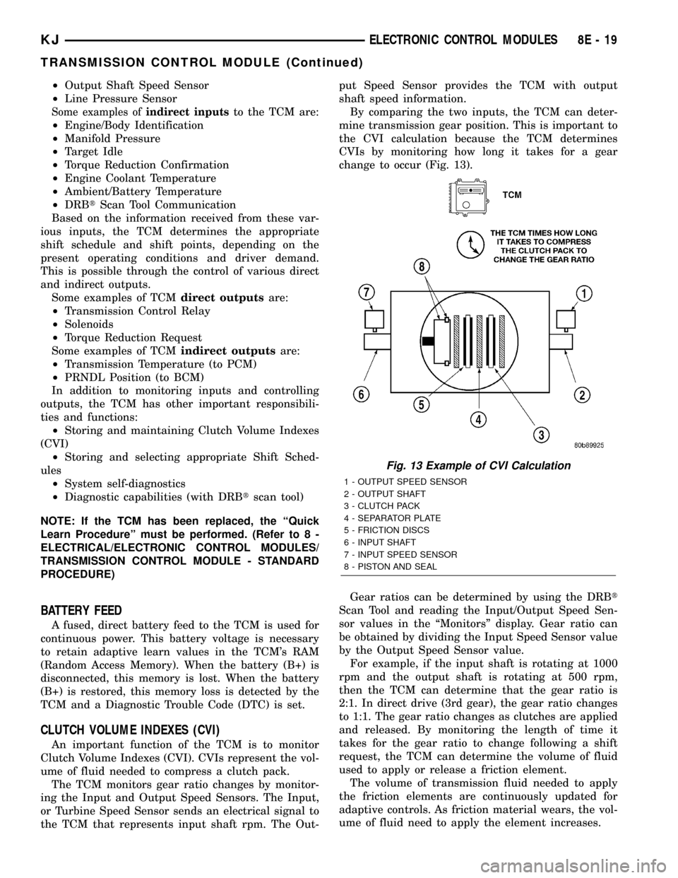
By comparing the two inputs, the TCM can deter-
mine transmission gear position. This is important to
the CVI calculation because the TCM determines
CVIs by monitoring how long it takes for a gear
change to occur (Fig. 13).
Gear ratios can be determined by using the DRBt
Scan Tool and reading the Input/Output Speed Sen-
sor values in the ªMonitorsº display. Gear ratio can
be obtained by dividing the Input Speed Sensor value
by the Output Speed Sensor value.
For example, if the input shaft is rotating at 1000
rpm and the output shaft is rotating at 500 rpm,
then the TCM can determine that the gear ratio is
2:1. In direct drive (3rd gear), the gear ratio changes
to 1:1. The gear ratio changes as clutches are applied
and released. By monitoring the length of time it
takes for the gear ratio to change following a shift
request, the TCM can determine the volume of fluid
used to apply or release a friction element.
The volume of transmission fluid needed to apply
the friction elements are continuously updated for
adaptive controls. As friction material wears, the vol-
ume of fluid need to apply the element increases.
Fig. 13 Example of CVI Calculation
1 - OUTPUT SPEED SENSOR
2 - OUTPUT SHAFT
3 - CLUTCH PACK
4 - SEPARATOR PLATE
5 - FRICTION DISCS
6 - INPUT SHAFT
7 - INPUT SPEED SENSOR
8 - PISTON AND SEAL
KJELECTRONIC CONTROL MODULES 8E - 19
TRANSMISSION CONTROL MODULE (Continued)
Page 641 of 1803
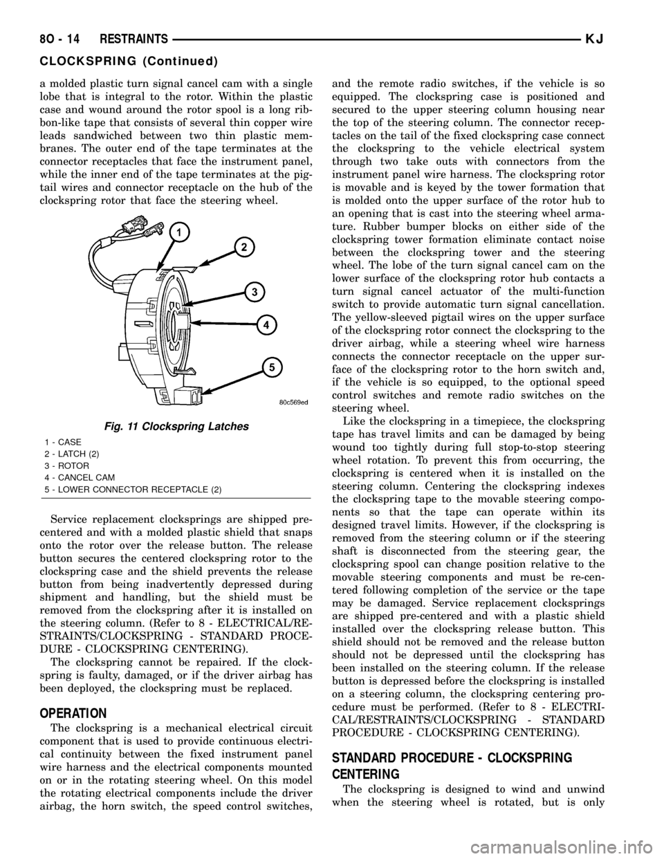
a molded plastic turn signal cancel cam with a single
lobe that is integral to the rotor. Within the plastic
case and wound around the rotor spool is a long rib-
bon-like tape that consists of several thin copper wire
leads sandwiched between two thin plastic mem-
branes. The outer end of the tape terminates at the
connector receptacles that face the instrument panel,
while the inner end of the tape terminates at the pig-
tail wires and connector receptacle on the hub of the
clockspring rotor that face the steering wheel.
Service replacement clocksprings are shipped pre-
centered and with a molded plastic shield that snaps
onto the rotor over the release button. The release
button secures the centered clockspring rotor to the
clockspring case and the shield prevents the release
button from being inadvertently depressed during
shipment and handling, but the shield must be
removed from the clockspring after it is installed on
the steering column. (Refer to 8 - ELECTRICAL/RE-
STRAINTS/CLOCKSPRING - STANDARD PROCE-
DURE - CLOCKSPRING CENTERING).
The clockspring cannot be repaired. If the clock-
spring is faulty, damaged, or if the driver airbag has
been deployed, the clockspring must be replaced.
OPERATION
The clockspring is a mechanical electrical circuit
component that is used to provide continuous electri-
cal continuity between the fixed instrument panel
wire harness and the electrical components mounted
on or in the rotating steering wheel. On this model
the rotating electrical components include the driver
airbag, the horn switch, the speed control switches,and the remote radio switches, if the vehicle is so
equipped. The clockspring case is positioned and
secured to the upper steering column housing near
the top of the steering column. The connector recep-
tacles on the tail of the fixed clockspring case connect
the clockspring to the vehicle electrical system
through two take outs with connectors from the
instrument panel wire harness. The clockspring rotor
is movable and is keyed by the tower formation that
is molded onto the upper surface of the rotor hub to
an opening that is cast into the steering wheel arma-
ture. Rubber bumper blocks on either side of the
clockspring tower formation eliminate contact noise
between the clockspring tower and the steering
wheel. The lobe of the turn signal cancel cam on the
lower surface of the clockspring rotor hub contacts a
turn signal cancel actuator of the multi-function
switch to provide automatic turn signal cancellation.
The yellow-sleeved pigtail wires on the upper surface
of the clockspring rotor connect the clockspring to the
driver airbag, while a steering wheel wire harness
connects the connector receptacle on the upper sur-
face of the clockspring rotor to the horn switch and,
if the vehicle is so equipped, to the optional speed
control switches and remote radio switches on the
steering wheel.
Like the clockspring in a timepiece, the clockspring
tape has travel limits and can be damaged by being
wound too tightly during full stop-to-stop steering
wheel rotation. To prevent this from occurring, the
clockspring is centered when it is installed on the
steering column. Centering the clockspring indexes
the clockspring tape to the movable steering compo-
nents so that the tape can operate within its
designed travel limits. However, if the clockspring is
removed from the steering column or if the steering
shaft is disconnected from the steering gear, the
clockspring spool can change position relative to the
movable steering components and must be re-cen-
tered following completion of the service or the tape
may be damaged. Service replacement clocksprings
are shipped pre-centered and with a plastic shield
installed over the clockspring release button. This
shield should not be removed and the release button
should not be depressed until the clockspring has
been installed on the steering column. If the release
button is depressed before the clockspring is installed
on a steering column, the clockspring centering pro-
cedure must be performed. (Refer to 8 - ELECTRI-
CAL/RESTRAINTS/CLOCKSPRING - STANDARD
PROCEDURE - CLOCKSPRING CENTERING).
STANDARD PROCEDURE - CLOCKSPRING
CENTERING
The clockspring is designed to wind and unwind
when the steering wheel is rotated, but is only
Fig. 11 Clockspring Latches
1 - CASE
2 - LATCH (2)
3 - ROTOR
4 - CANCEL CAM
5 - LOWER CONNECTOR RECEPTACLE (2)
8O - 14 RESTRAINTSKJ
CLOCKSPRING (Continued)
Page 642 of 1803
designed to rotate the same number of turns (about
five complete rotations) as the steering wheel can be
turned from stop to stop. Centering the clockspring
indexes the clockspring tape to other steering compo-
nents so that it can operate within its designed
travel limits. The rotor of a centered clockspring can
be rotated two and one-half turns in either direction
from the centered position, without damaging the
clockspring tape.
However, if the clockspring is removed for service
or if the steering column is disconnected from the
steering gear, the clockspring tape can change posi-
tion relative to the other steering components. The
clockspring must then be re-centered following com-
pletion of such service or the clockspring tape may be
damaged. Service replacement clocksprings are
shipped pre-centered, with the release button
engaged (raised) and a molded plastic shield installed
over the release button. This release button should
not be disengaged and the shield should not be
removed until the clockspring has been installed on
the steering column. If the release button is disen-
gaged before the clockspring is installed on a steering
column, the clockspring centering procedure must be
performed.
WARNING: ON VEHICLES EQUIPPED WITH AIR-
BAGS, DISABLE THE SUPPLEMENTAL RESTRAINT
SYSTEM BEFORE ATTEMPTING ANY STEERING
WHEEL, STEERING COLUMN, DRIVER AIRBAG,
PASSENGER AIRBAG, SEAT BELT TENSIONER,
FRONT IMPACT SENSORS, SIDE CURTAIN AIRBAG,
OR INSTRUMENT PANEL COMPONENT DIAGNOSIS
OR SERVICE. DISCONNECT AND ISOLATE THE
BATTERY NEGATIVE (GROUND) CABLE, THEN
WAIT TWO MINUTES FOR THE SYSTEM CAPACI-
TOR TO DISCHARGE BEFORE PERFORMING FUR-
THER DIAGNOSIS OR SERVICE. THIS IS THE ONLY
SURE WAY TO DISABLE THE SUPPLEMENTAL
RESTRAINT SYSTEM. FAILURE TO TAKE THE
PROPER PRECAUTIONS COULD RESULT IN ACCI-
DENTAL AIRBAG DEPLOYMENT AND POSSIBLE
PERSONAL INJURY.
NOTE: Before starting this procedure, be certain to
turn the steering wheel until the front wheels are in
the straight-ahead position.
(1) Place the front wheels in the straight-ahead
position.
(2) Remove the clockspring from the steering col-
umn. (Refer to 8 - ELECTRICAL/RESTRAINTS/
CLOCKSPRING - REMOVAL).
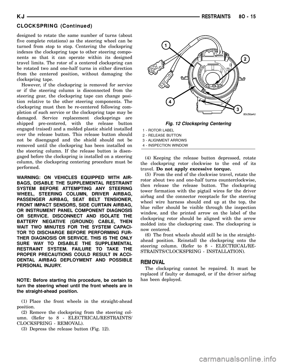
(3) Depress the release button (Fig. 12).(4) Keeping the release button depressed, rotate
the clockspring rotor clockwise to the end of its
travel.Do not apply excessive torque.
(5) From the end of the clockwise travel, rotate the
rotor about two and one-half turns counterclockwise,
then release the release button. The clockspring
tower formation with the pigtail wires for the driver
airbag and the connector receptacle for the steering
wheel wire harness should end up at the top, the
blue roller should be visible through the inspection
window, and the printed arrow on the label of the
clockspring rotor should be aligned with the arrow
molded into the clockspring case. The clockspring is
now centered.
(6) The front wheels should still be in the straight-
ahead position. Reinstall the clockspring onto the
steering column. (Refer to 8 - ELECTRICAL/RE-
STRAINTS/CLOCKSPRING - INSTALLATION).
REMOVAL
The clockspring cannot be repaired. It must be
replaced if faulty or damaged, or if the driver airbag
has been deployed.
Fig. 12 Clockspring Centering
1 - ROTOR LABEL
2 - RELEASE BUTTON
3 - ALIGNMENT ARROWS
4 - INSPECTION WINDOW
KJRESTRAINTS 8O - 15
CLOCKSPRING (Continued)