JEEP RENEGADE 2015 1.G Owners Manual
RENEGADE 2015 1.G
JEEP
JEEP
https://www.carmanualsonline.info/img/16/7149/w960_7149-0.png
JEEP RENEGADE 2015 1.G Owners Manual
Trending: headlight, brake fluid, sat nav, keyless entry, overheating, service indicator, coolant reservoir
Page 471 of 678
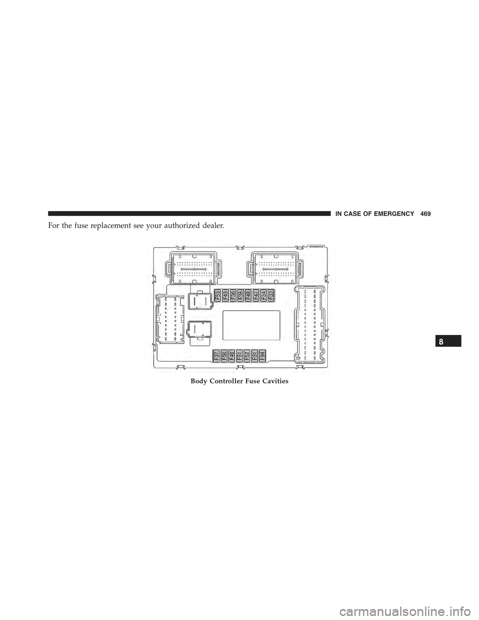
For the fuse replacement see your authorized dealer.
Body Controller Fuse Cavities
8
IN CASE OF EMERGENCY 469
Page 472 of 678
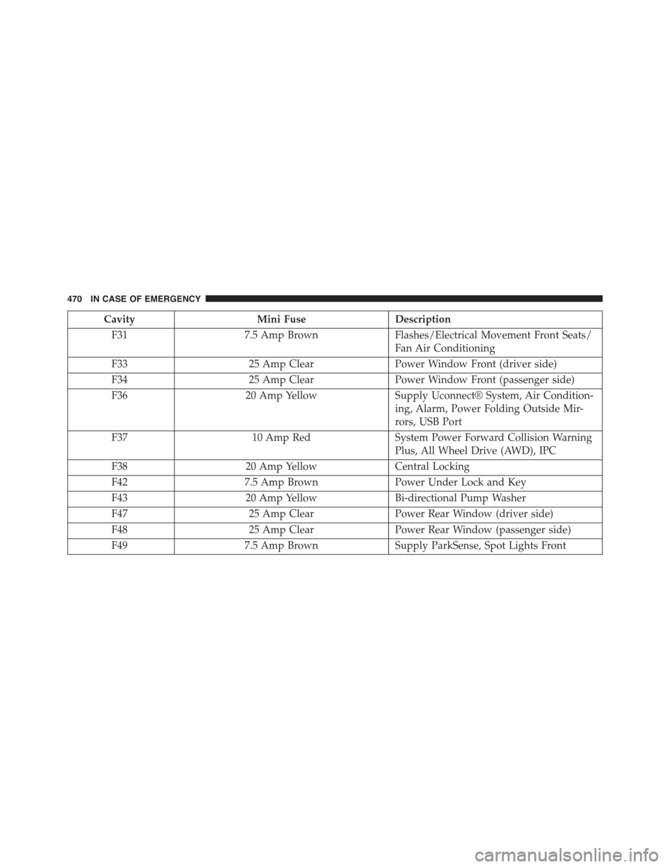
CavityMini FuseDescription
F317.5 Amp BrownFlashes/Electrical Movement Front Seats/
Fan Air Conditioning
F3325 Amp ClearPower Window Front (driver side)
F3425 Amp ClearPower Window Front (passenger side)
F3620 Amp YellowSupply Uconnect® System, Air Condition-
ing, Alarm, Power Folding Outside Mir-
rors, USB Port
F3710 Amp RedSystem Power Forward Collision Warning
Plus, All Wheel Drive (AWD), IPC
F3820 Amp YellowCentral Locking
F427.5 Amp BrownPower Under Lock and Key
F4320 Amp YellowBi-directional Pump Washer
F4725 Amp ClearPower Rear Window (driver side)
F4825 Amp ClearPower Rear Window (passenger side)
F497.5 Amp BrownSupply ParkSense, Spot Lights Front
470 IN CASE OF EMERGENCY
Page 473 of 678
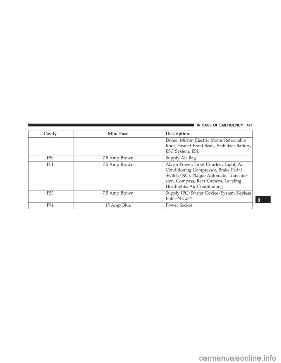
CavityMini FuseDescription
Dome, Mirror, Electric Motor Retractable
Roof, Heated Front Seats, Stabilizer Battery,
ESC System, ESL
F507.5 Amp BrownSupply Air Bag
F517.5 Amp BrownAlarm Power, Front Courtesy Light, Air
Conditioning Compressor, Brake Pedal
Switch (NC), Plaque Automatic Transmis-
sion, Compass, Rear Camera, Leveling
Headlights, Air Conditioning
F537.5 Amp BrownSupply IPC/Starter Device/System Keyless
Enter-N-Go™
F9415 Amp BluePower Socket
8
IN CASE OF EMERGENCY 471
Page 474 of 678
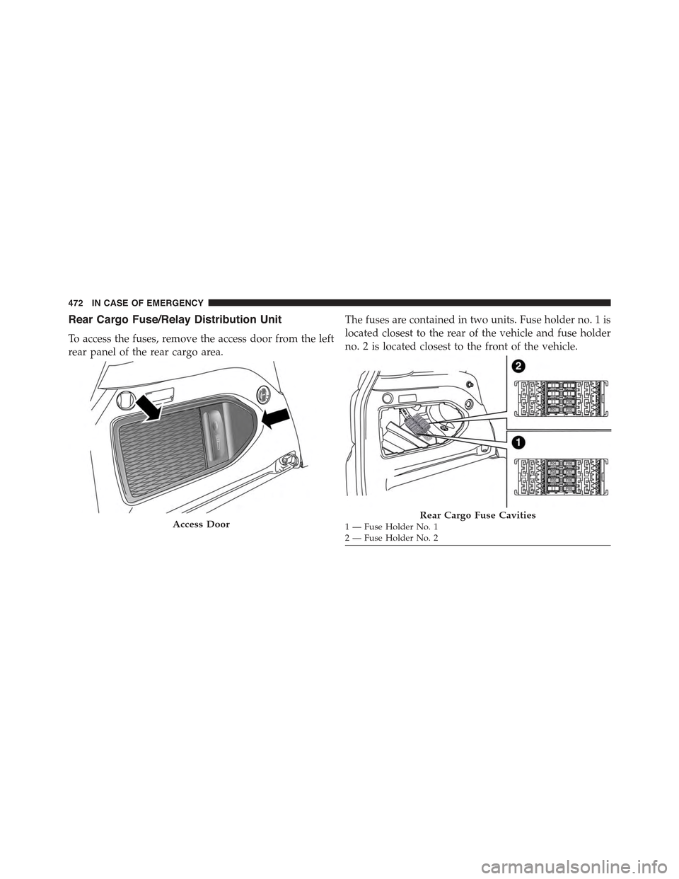
Rear Cargo Fuse/Relay Distribution Unit
To access the fuses, remove the access door from the left
rear panel of the rear cargo area.
The fuses are contained in two units. Fuse holder no. 1 is
located closest to the rear of the vehicle and fuse holder
no. 2 is located closest to the front of the vehicle.
Access DoorRear Cargo Fuse Cavities1—FuseHolderNo.12—FuseHolderNo.2
472 IN CASE OF EMERGENCY
Page 475 of 678
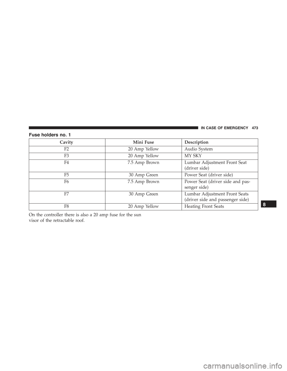
Fuse holders no. 1
CavityMini FuseDescription
F220 Amp YellowAudio System
F320 Amp YellowMY SKY
F47.5 Amp BrownLumbar Adjustment Front Seat
(driver side)
F530 Amp GreenPower Seat (driver side)
F67.5 Amp BrownPower Seat (driver side and pas-
senger side)
F730 Amp GreenLumbar Adjustment Front Seats
(driver side and passenger side)
F820 Amp YellowHeating Front Seats
On the controller there is also a 20 amp fuse for the sun
visor of the retractable roof.
8
IN CASE OF EMERGENCY 473
Page 476 of 678
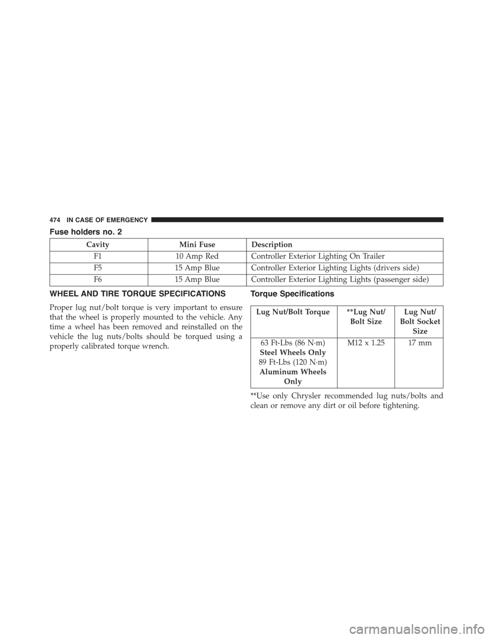
Fuse holders no. 2
CavityMini Fuse Description
F110 Amp Red Controller Exterior Lighting On Trailer
F515 Amp Blue Controller Exterior Lighting Lights (drivers side)
F615 Amp Blue Controller Exterior Lighting Lights (passenger side)
WHEEL AND TIRE TORQUE SPECIFICATIONS
Proper lug nut/bolt torque is very important to ensure
that the wheel is properly mounted to the vehicle. Any
time a wheel has been removed and reinstalled on the
vehicle the lug nuts/bolts should be torqued using a
properly calibrated torque wrench.
Torque Specifications
Lug Nut/Bolt Torque **Lug Nut/
Bolt Size
Lug Nut/
Bolt Socket
Size
63 Ft-Lbs (86 N·m)
Steel Wheels Only
89 Ft-Lbs (120 N·m)
Aluminum Wheels
Only
M12 x 1.25 17 mm
**Use only Chrysler recommended lug nuts/bolts and
clean or remove any dirt or oil before tightening.
474 IN CASE OF EMERGENCY
Page 477 of 678
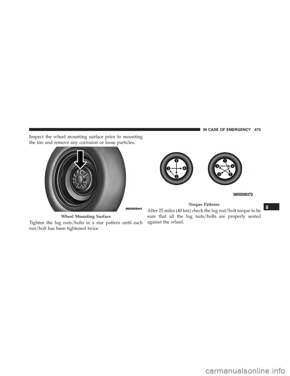
Inspect the wheel mounting surface prior to mounting
the tire and remove any corrosion or loose particles.
Tighten the lug nuts/bolts in a star pattern until each
nut/bolt has been tightened twice.
After 25 miles (40 km) check the lug nut/bolt torque to be
sure that all the lug nuts/bolts are properly seated
against the wheel.
Wheel Mounting Surface
Torque Patterns8
IN CASE OF EMERGENCY 475
Page 478 of 678
WARNING!
To avoid the risk of forcing the vehicle off the jack,
do not tighten the lug nuts fully until the vehicle has
been lowered. Failure to follow this warning may
result in personal injury.
JACKING AND TIRE CHANGING
WARNING!
•Do not attempt to change a tire on the side of the
vehicle close to moving traffic. Pull far enough off
the road to avoid the danger of being hit when
operating the jack or changing the wheel.
(Continued)
WARNING!(Continued)
•Being under a jacked-up vehicle is dangerous. The
vehicle could slip off the jack and fall on you. You
could be crushed. Never put any part of your body
under a vehicle that is on a jack. If you need to get
under a raised vehicle, take it to a service center
where it can be raised on a lift.
•Never start or run the engine while the vehicle is
on a jack.
•The jack is designed to be used as a tool for
changing tires only. The jack should not be used to
lift the vehicle for service purposes. The vehicle
should be jacked on a firm level surface only.
Avoid ice or slippery areas.
476 IN CASE OF EMERGENCY
Page 479 of 678
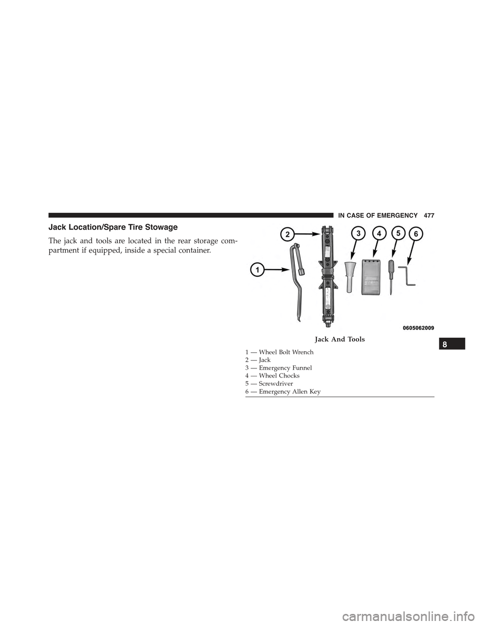
Jack Location/Spare Tire Stowage
The jack and tools are located in the rear storage com-
partment if equipped, inside a special container.
Jack And Tools
1—WheelBoltWrench2 — Jack3—EmergencyFunnel4 — Wheel Chocks5 — Screwdriver6 — Emergency Allen Key
8
IN CASE OF EMERGENCY 477
Page 480 of 678
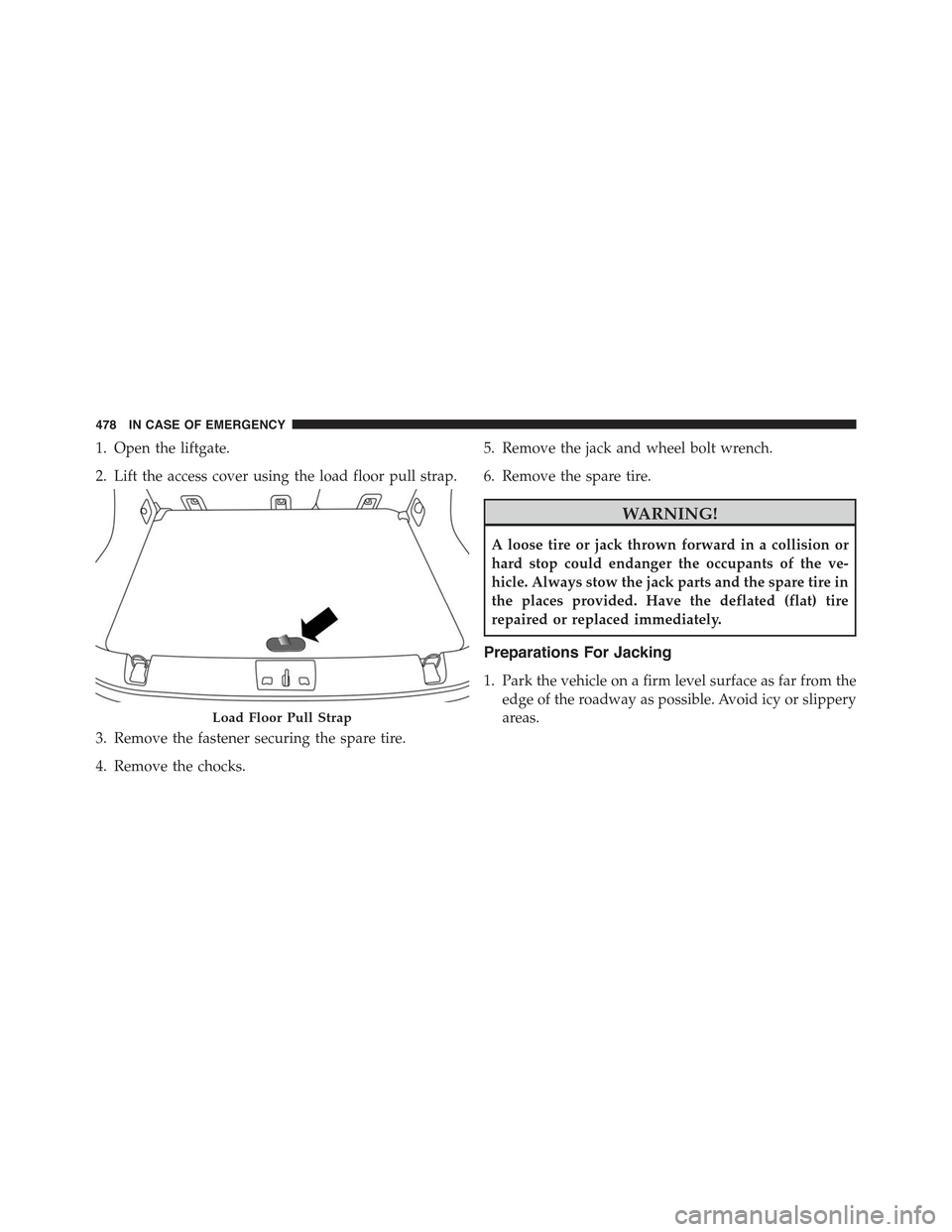
1. Open the liftgate.
2. Lift the access cover using the load floor pull strap.
3. Remove the fastener securing the spare tire.
4. Remove the chocks.
5. Remove the jack and wheel bolt wrench.
6. Remove the spare tire.
WARNING!
A loose tire or jack thrown forward in a collision or
hard stop could endanger the occupants of the ve-
hicle. Always stow the jack parts and the spare tire in
the places provided. Have the deflated (flat) tire
repaired or replaced immediately.
Preparations For Jacking
1. Park the vehicle on a firm level surface as far from the
edge of the roadway as possible. Avoid icy or slippery
areas.Load Floor Pull Strap
478 IN CASE OF EMERGENCY
Trending: trailer, winter tires, key battery, keyless, diagram, manual transmission, USB
