JEEP RENEGADE 2015 1.G Owners Manual
RENEGADE 2015 1.G
JEEP
JEEP
https://www.carmanualsonline.info/img/16/7149/w960_7149-0.png
JEEP RENEGADE 2015 1.G Owners Manual
Trending: mirror controls, brake rotor, heater, tire pressure, manual transmission, lock, set clock
Page 461 of 678
3. Close the light cover over the bulb.
4. Reinstall the dome light in its correct position.
WARNING!
•Before proceeding with the replacement of the
lamp wait for the exhaust pipes are cool: DANGER
OF BURNS!
•Modifications or repair of the electrical system
performed incorrectly and without taking into ac-
count the technical characteristics can cause mal-
functions with the risk of fire.
•Halogen lamps contain gas under pressure, in the
event of breakage be careful of the projection of
fragments of glass.
(Continued)
WARNING!(Continued)
•Halogen lamps must be handled by touching only
the metallic part. If the transparent bulb is in
contact with the fingers, reduces the intensity of
the emitted light and you can also affect the life of
the lamp. In case of accidental contact, rub the bulb
with a cloth dampened with alcohol and allow to
dry.
8
IN CASE OF EMERGENCY 459
Page 462 of 678
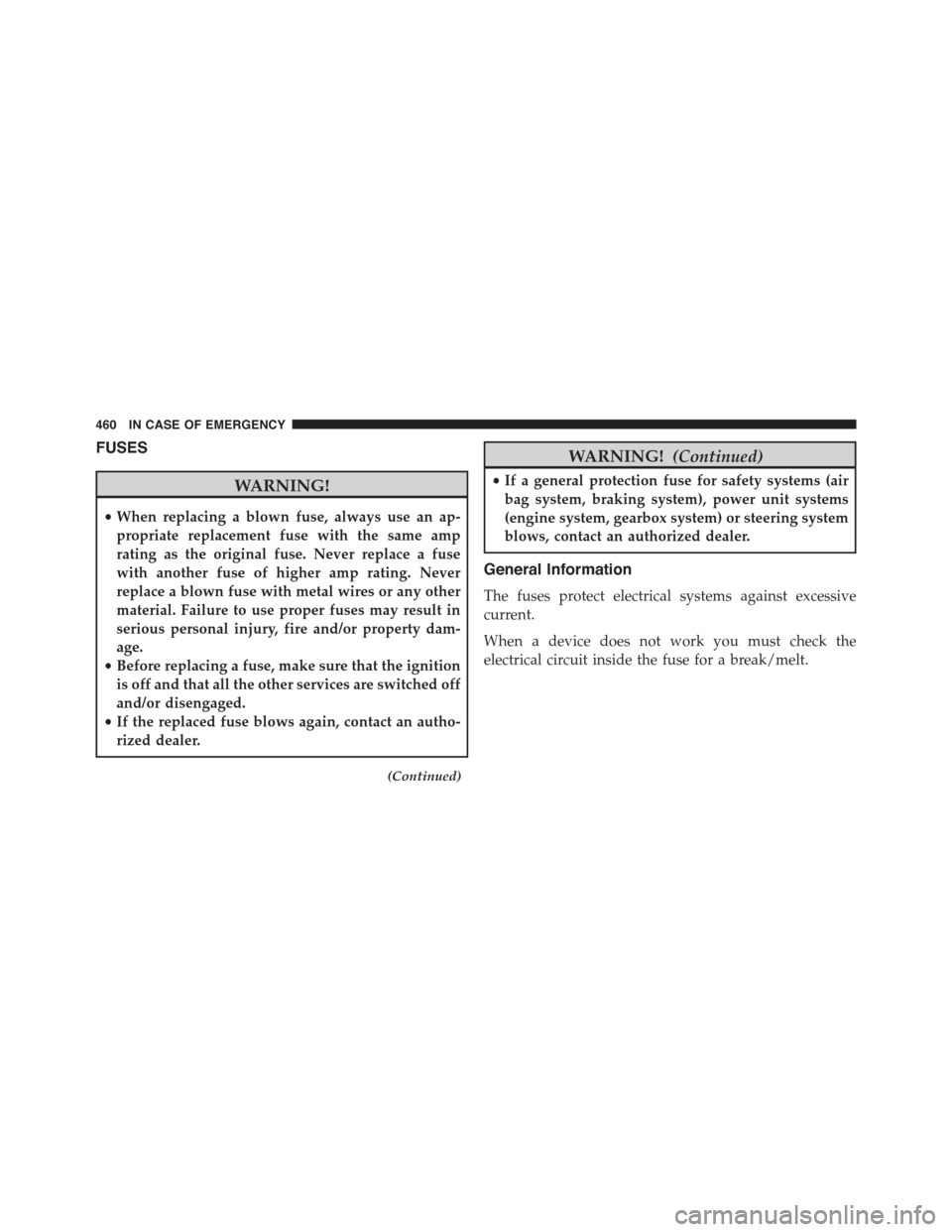
FUSES
WARNING!
•When replacing a blown fuse, always use an ap-
propriate replacement fuse with the same amp
rating as the original fuse. Never replace a fuse
with another fuse of higher amp rating. Never
replace a blown fuse with metal wires or any other
material. Failure to use proper fuses may result in
serious personal injury, fire and/or property dam-
age.
•Before replacing a fuse, make sure that the ignition
is off and that all the other services are switched off
and/or disengaged.
•If the replaced fuse blows again, contact an autho-
rized dealer.
(Continued)
WARNING!(Continued)
•If a general protection fuse for safety systems (air
bag system, braking system), power unit systems
(engine system, gearbox system) or steering system
blows, contact an authorized dealer.
General Information
The fuses protect electrical systems against excessive
current.
When a device does not work you must check the
electrical circuit inside the fuse for a break/melt.
460 IN CASE OF EMERGENCY
Page 463 of 678
Fuse Removal
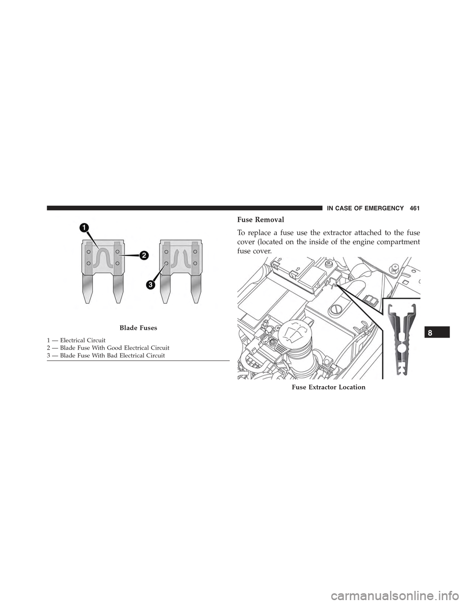
To replace a fuse use the extractor attached to the fuse
cover (located on the inside of the engine compartment
fuse cover.
Blade Fuses
1 — Electrical Circuit2 — Blade Fuse With Good Electrical Circuit3 — Blade Fuse With Bad Electrical Circuit
Fuse Extractor Location
8
IN CASE OF EMERGENCY 461
Page 464 of 678
Access To The Fuses
The fuses are grouped into four controllers located in the
engine compartment, under the instrument panel and on
the inside of the left side cargo trim panel.
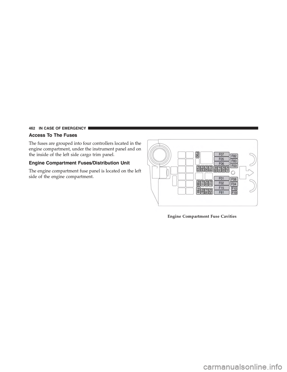
Engine Compartment Fuses/Distribution Unit
The engine compartment fuse panel is located on the left
side of the engine compartment.
Engine Compartment Fuse Cavities
462 IN CASE OF EMERGENCY
Page 465 of 678
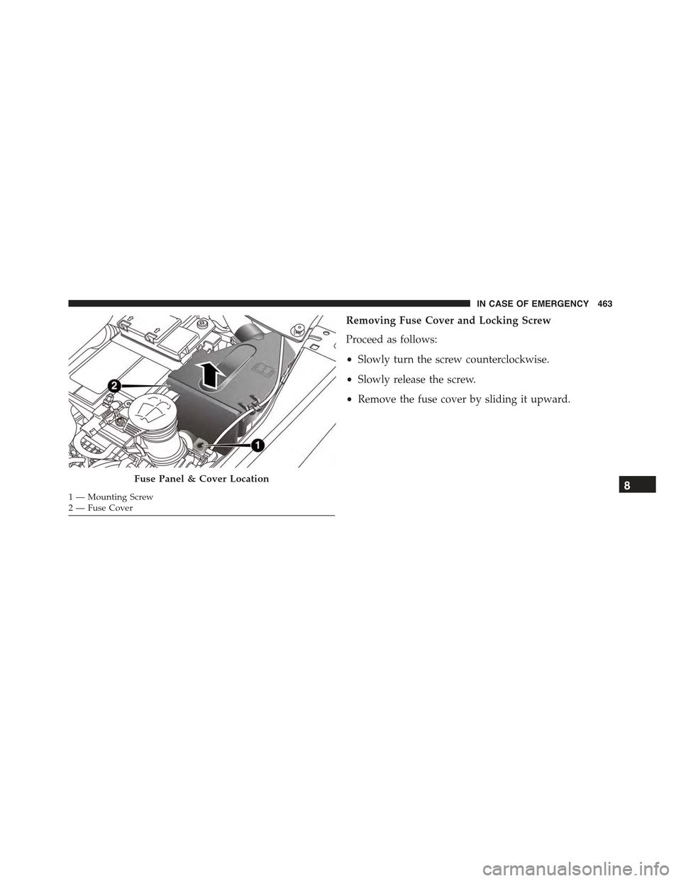
Removing Fuse Cover and Locking Screw
Proceed as follows:
•Slowly turn the screw counterclockwise.
•Slowly release the screw.
•Remove the fuse cover by sliding it upward.
Fuse Panel & Cover Location
1 — Mounting Screw2—FuseCover
8
IN CASE OF EMERGENCY 463
Page 466 of 678
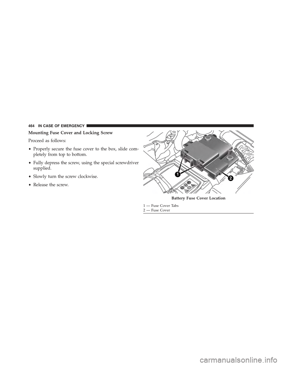
Mounting Fuse Cover and Locking Screw
Proceed as follows:
•Properly secure the fuse cover to the box, slide com-
pletely from top to bottom.
•Fully depress the screw, using the special screwdriver
supplied.
•Slowly turn the screw clockwise.
•Release the screw.
Battery Fuse Cover Location
1—FuseCoverTabs2—FuseCover
464 IN CASE OF EMERGENCY
Page 467 of 678
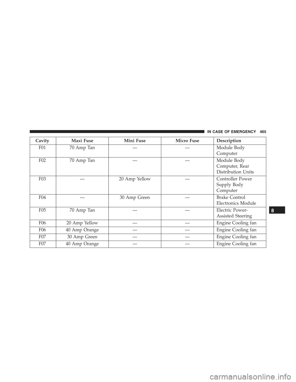
Cavity Maxi FuseMini FuseMicro Fuse Description
F0170 Amp Tan——Module Body
Computer
F0270 Amp Tan——Module Body
Computer, Rear
Distribution Units
F03—20 Amp Yellow—Controller Power
Supply Body
Computer
F04—30 Amp Green—Brake Control
Electronics Module
F0570 Amp Tan——Electric Power-
Assisted Steering
F06 20 Amp Yellow——Engine Cooling fan
F06 40 Amp Orange——Engine Cooling fan
F07 30 Amp Green——Engine Cooling fan
F07 40 Amp Orange——Engine Cooling fan
8
IN CASE OF EMERGENCY 465
Page 468 of 678
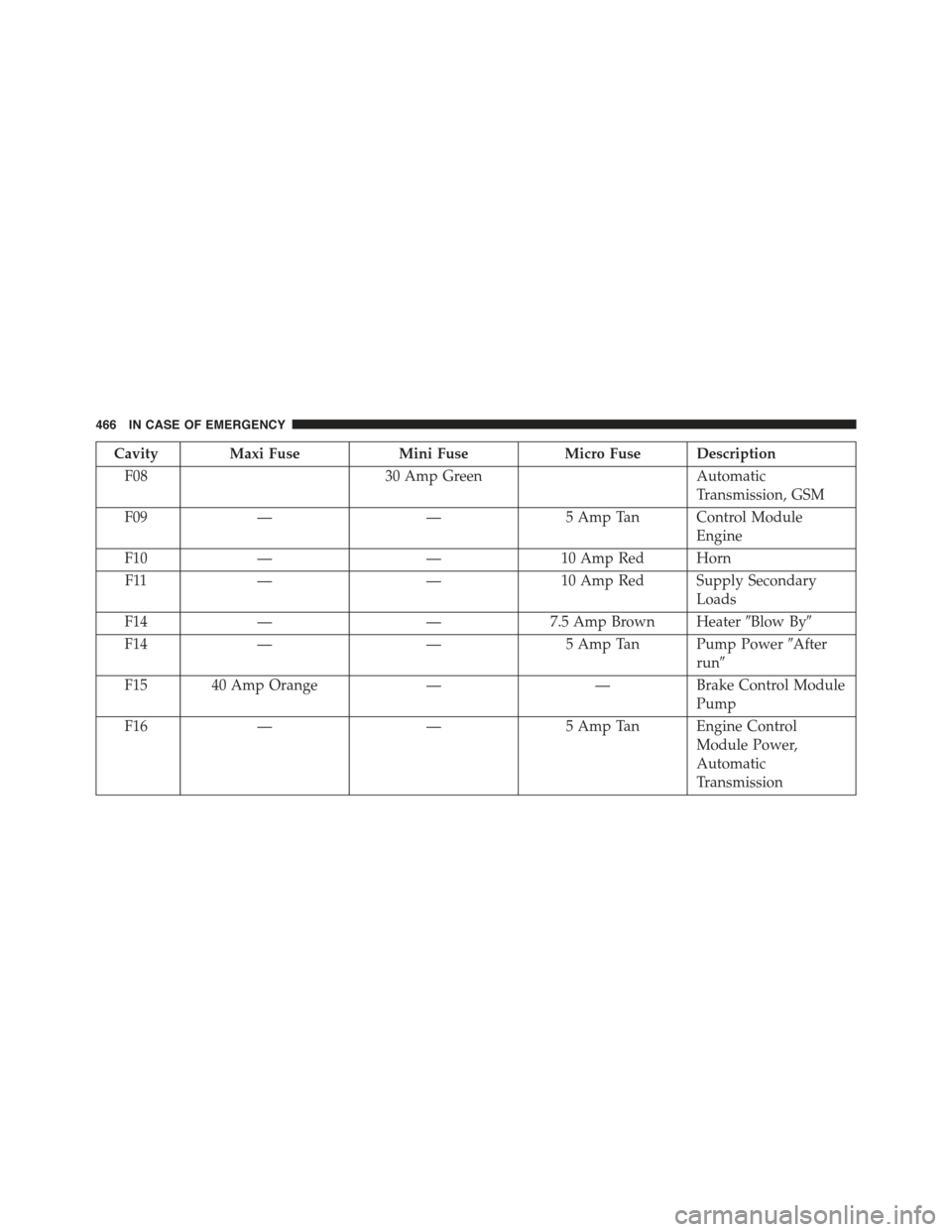
Cavity Maxi FuseMini FuseMicro Fuse Description
F0830 Amp GreenAutomatic
Transmission, GSM
F09——5 Amp Tan Control Module
Engine
F10——10 Amp Red Horn
F11——10 Amp Red Supply Secondary
Loads
F14——7.5 Amp Brown Heater#Blow By#
F14——5 Amp Tan Pump Power#After
run#
F15 40 Amp Orange——Brake Control Module
Pump
F16——5 Amp Tan Engine Control
Module Power,
Automatic
Transmission
466 IN CASE OF EMERGENCY
Page 469 of 678
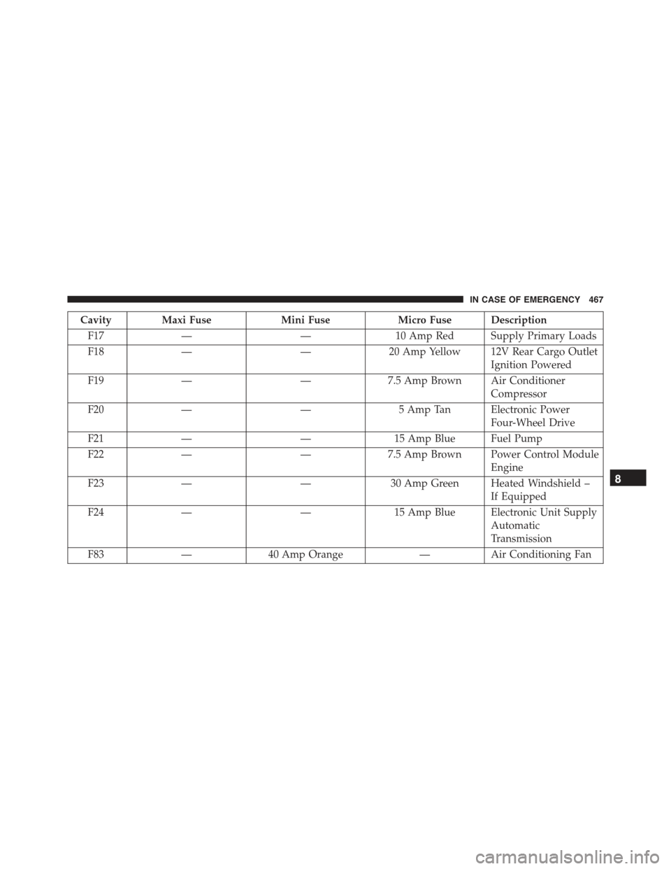
Cavity Maxi FuseMini FuseMicro Fuse Description
F17——10 Amp Red Supply Primary Loads
F18——20 Amp Yellow 12V Rear Cargo Outlet
Ignition Powered
F19——7.5 Amp Brown Air Conditioner
Compressor
F20——5 Amp Tan Electronic Power
Four-Wheel Drive
F21——15 Amp Blue Fuel Pump
F22——7.5 Amp Brown Power Control Module
Engine
F23——30 Amp Green Heated Windshield –
If Equipped
F24——15 Amp Blue Electronic Unit Supply
Automatic
Transmission
F83—40 Amp Orange—Air Conditioning Fan
8
IN CASE OF EMERGENCY 467
Page 470 of 678
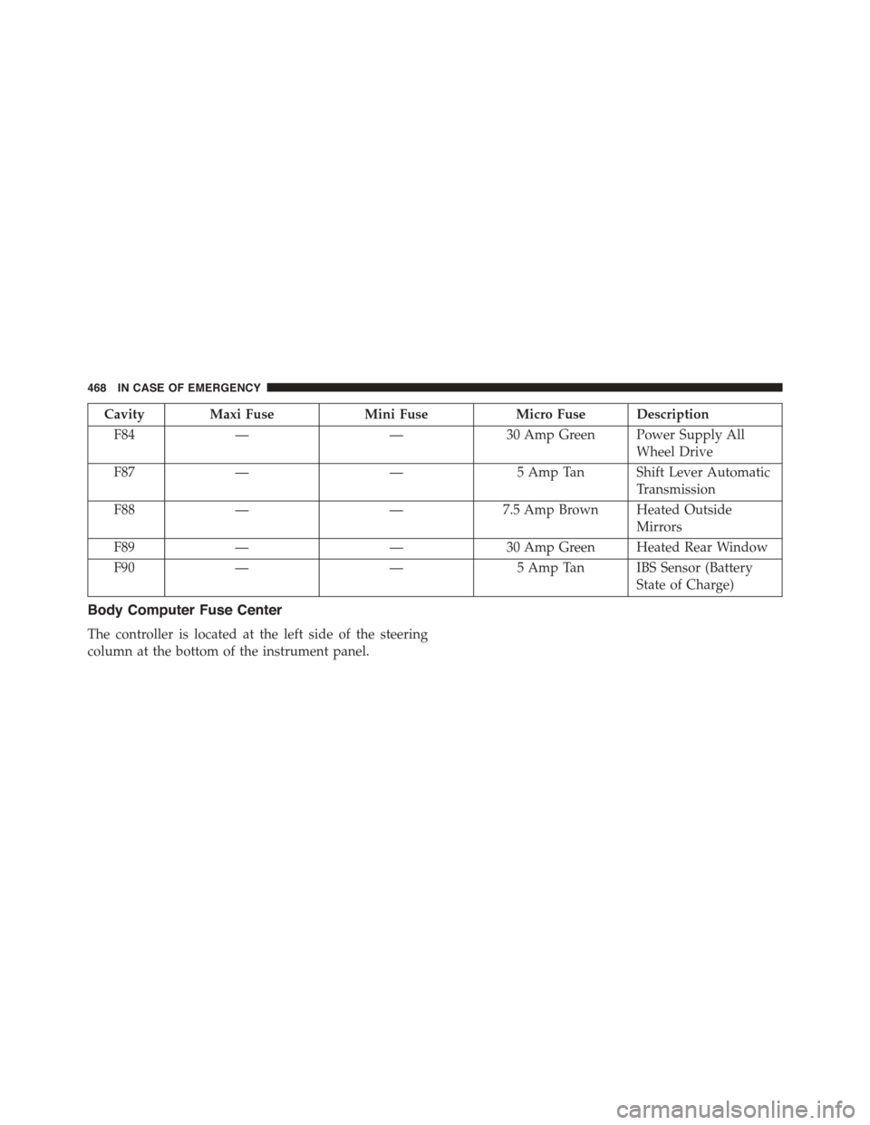
Cavity Maxi FuseMini FuseMicro Fuse Description
F84——30 Amp Green Power Supply All
Wheel Drive
F87——5 Amp Tan Shift Lever Automatic
Transmission
F88——7.5 Amp Brown Heated Outside
Mirrors
F89——30 Amp Green Heated Rear Window
F90——5 Amp Tan IBS Sensor (Battery
State of Charge)
Body Computer Fuse Center
The controller is located at the left side of the steering
column at the bottom of the instrument panel.
468 IN CASE OF EMERGENCY
Trending: language, open hood, parking sensors, dashboard, steering wheel adjustment, heating, display
