light JEEP RENEGADE 2018 Owner handbook (in English)
[x] Cancel search | Manufacturer: JEEP, Model Year: 2018, Model line: RENEGADE, Model: JEEP RENEGADE 2018Pages: 356, PDF Size: 6.11 MB
Page 35 of 356
If the headlights are switched off before
the ignition, they will switch off normally.
MAIN BEAM HEADLIGHTS
To activate the fixed main beam
headlights, with the ignition device in
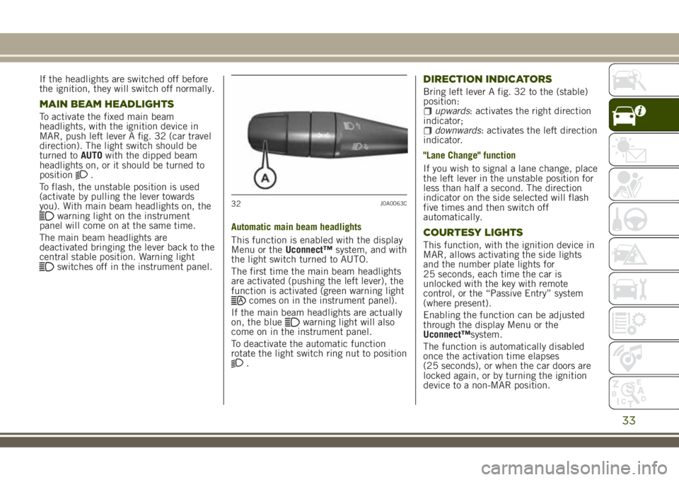
MAR, push left lever A fig. 32 (car travel
direction). The light switch should be
turned toAUTOwith the dipped beam
headlights on, or it should be turned to
position
.
To flash, the unstable position is used
(activate by pulling the lever towards
you). With main beam headlights on, the
warning light on the instrument
panel will come on at the same time.
The main beam headlights are
deactivated bringing the lever back to the
central stable position. Warning light
switches off in the instrument panel.Automatic main beam headlights
This function is enabled with the display
Menu or theUconnect™system, and with
the light switch turned to AUTO.
The first time the main beam headlights
are activated (pushing the left lever), the
function is activated (green warning light
comes on in the instrument panel).
If the main beam headlights are actually
on, the blue
warning light will also
come on in the instrument panel.
To deactivate the automatic function
rotate the light switch ring nut to position
.
DIRECTION INDICATORS
Bring left lever A fig. 32 to the (stable)
position:
upwards: activates the right direction
indicator;
downwards: activates the left direction
indicator.
"Lane Change" function
If you wish to signal a lane change, place
the left lever in the unstable position for
less than half a second. The direction
indicator on the side selected will flash
five times and then switch off
automatically.
COURTESY LIGHTS
This function, with the ignition device in
MAR, allows activating the side lights
and the number plate lights for
25 seconds, each time the car is
unlocked with the key with remote
control, or the “Passive Entry” system
(where present).
Enabling the function can be adjusted
through the display Menu or the
Uconnect™system.
The function is automatically disabled
once the activation time elapses
(25 seconds), or when the car doors are
locked again, or by turning the ignition
device to a non-MAR position.
32J0A0063C
33
Page 36 of 356
HEADLIGHT REGULATION
Headlight corrector
It only works with the starter device in
position MAR and the low beams on.
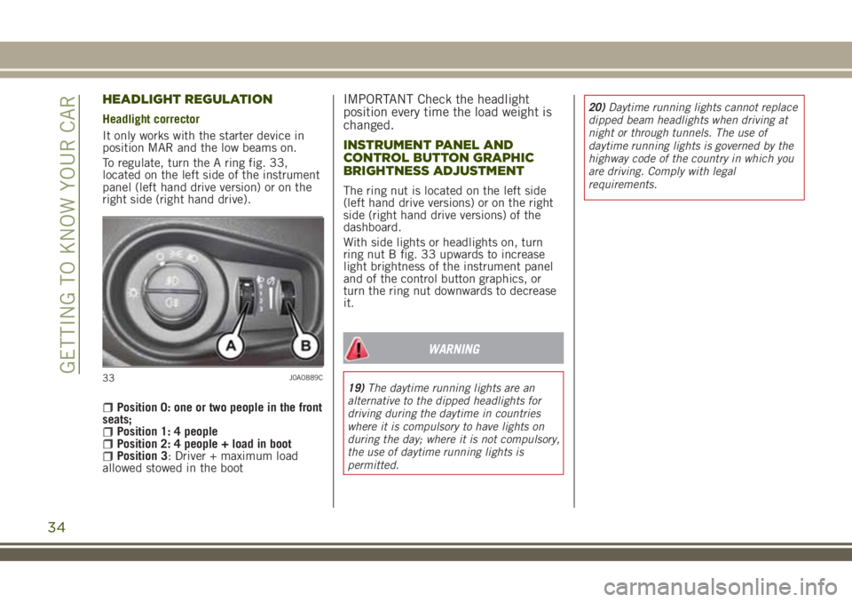
To regulate, turn the A ring fig. 33,
located on the left side of the instrument
panel (left hand drive version) or on the
right side (right hand drive).
Position 0: one or two people in the front
seats;
Position 1: 4 peoplePosition 2: 4 people + load in bootPosition 3: Driver + maximum load
allowed stowed in the boot
IMPORTANT Check the headlight
position every time the load weight is
changed.
INSTRUMENT PANEL AND
CONTROL BUTTON GRAPHIC
BRIGHTNESS ADJUSTMENT
The ring nut is located on the left side
(left hand drive versions) or on the right
side (right hand drive versions) of the
dashboard.
With side lights or headlights on, turn
ring nut B fig. 33 upwards to increase
light brightness of the instrument panel
and of the control button graphics, or
turn the ring nut downwards to decrease
it.
WARNING
19)The daytime running lights are an
alternative to the dipped headlights for
driving during the daytime in countries
where it is compulsory to have lights on
during the day; where it is not compulsory,
the use of daytime running lights is
permitted.20)Daytime running lights cannot replace
dipped beam headlights when driving at
night or through tunnels. The use of
daytime running lights is governed by the
highway code of the country in which you
are driving. Comply with legal
requirements.33J0A0889C
34
GETTING TO KNOW YOUR CAR
Page 37 of 356
INTERIOR LIGHTS
FRONT CEILING LIGHT
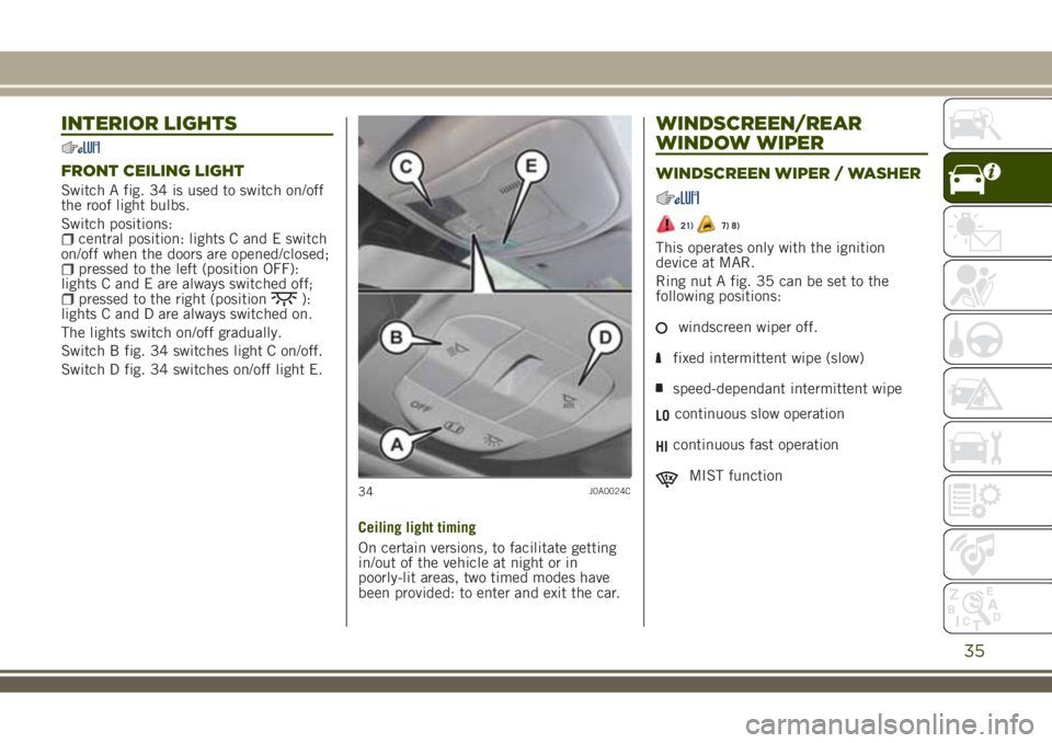
Switch A fig. 34 is used to switch on/off
the roof light bulbs.
Switch positions:
central position: lights C and E switch
on/off when the doors are opened/closed;
pressed to the left (position OFF):
lights C and E are always switched off;
pressed to the right (position):
lights C and D are always switched on.
The lights switch on/off gradually.
Switch B fig. 34 switches light C on/off.
Switch D fig. 34 switches on/off light E.
Ceiling light timing
On certain versions, to facilitate getting
in/out of the vehicle at night or in
poorly-lit areas, two timed modes have
been provided: to enter and exit the car.
WINDSCREEN/REAR
WINDOW WIPER
WINDSCREEN WIPER / WASHER
21)7) 8)
This operates only with the ignition
device at MAR.
Ring nut A fig. 35 can be set to the
following positions:
windscreen wiper off.
fixed intermittent wipe (slow)
speed-dependant intermittent wipe
LOcontinuous slow operation
HIcontinuous fast operation
MIST function34J0A0024C
35
Page 41 of 356
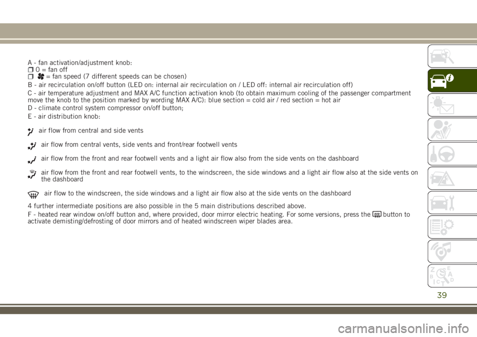
A - fan activation/adjustment knob:0 = fan off= fan speed (7 different speeds can be chosen)
B - air recirculation on/off button (LED on: internal air recirculation on / LED off: internal air recirculation off)
C - air temperature adjustment and MAX A/C function activation knob (to obtain maximum cooling of the passenger compartment
move the knob to the position marked by wording MAX A/C): blue section = cold air / red section = hot air
39
D - climate control system compressor on/off button;
E - air distribution knob:
air flow from central and side vents
air flow from central vents, side vents and front/rear footwell vents
air flow from the front and rear footwell vents and a light air flow also from the side vents on the dashboard
air flow from the front and rear footwell vents, to the windscreen, the side windows and a light air flow also at the side vents on
the dashboard
air flow to the windscreen, the side windows and a light air flow also at the side vents on the dashboard
4 further intermediate positions are also possible in the 5 main distributions described above.
F - heated rear window on/off button and, where provided, door mirror electric heating. For some versions, press the
button to
activate demisting/defrosting of door mirrors and of heated windscreen wiper blades area.
Page 50 of 356
Proceed as follows:move the roof to fully closed position;move the ignition device to STOP and
keep it there for 10 seconds;
move the ignition device to MAR;press button A: fig. 40 in "closing"
position;
press the button for at least
10 seconds, then you should hear the
mechanical stop of the roof motor;
press the button A in the "closing"
position again within 5 seconds;
hold down button A: in this position,
the roof will perform an automatic
opening and closing cycle. Otherwise,
repeat the operations starting from the
beginning;
hold down button A until the roof is
completely closed: the initialisation
procedure has ended.
WARNING
23)When leaving the vehicle (equipped
with mechanical key with a remote
control), always remove the key from the
ignition device to avoid the risk of injury
to those still inside the vehicle due to
accidental operation of the sun roof.
Improper use of the roof can be
dangerous. Before and during operation,
always check that no-one is exposed to the
risk of being injured by the moving
sunroof or by objects getting caught or hit
by it.
IMPORTANT
11)Do not open the sun roof if a
transverse roof rack is fitted. Do not open
the sun roof if there is snow or ice on it:
you may damage it.
MySky SUN ROOF
12)
The roof has two panels, a front and a
rear one, that can be individually or
simultaneously removed, as wished.
Front and rear panels are distinguished
by a dedicated symbol on the bottom of
the panels themselves.
IMPORTANT The panels can withstand
any snow that may deposit on them. In
any case, it is advisable to remove
excessive snow.
FRONT PANEL ELECTRIC
MOVEMENT
On some versions, the front panel might
be electrically operated.
This operates only with the ignition
device at MAR. The panel can be
adjusted forward/backward and opened
in “swivel” position.
The buttons to operate the front panel
are located on the trim close to the front
ceiling light fig. 42:
Button A: open/close the front panel to
the end of its travel. Press button A to
fully open the front glass panel. Pull the
button: the front panel will close fully.
48
GETTING TO KNOW YOUR CAR
Page 63 of 356
KNOWING THE INSTRUMENT PANEL
This section of the booklet gives you all
the information you need to understand,
interpret and use the instrument panel
correctly.EOBD SYSTEM (European On Board
Diagnosis)..................62
CONTROL PANEL AND ON-BOARD
INSTRUMENTS..............63
DISPLAY...................67
TRIP COMPUTER.............70
WARNING LIGHTS AND MESSAGES .71
61
Page 64 of 356
EOBD SYSTEM (European
On Board Diagnosis)
(where provided)
OPERATION
The EOBD system (European On Board
Diagnosis) carries out a continuous
diagnosis of the components of the car
related to emissions.
It also alerts the driver, by switching on
the
warning light on the instrument
panel, together with a message on the
display, when these components are no
longer in peak condition (see “Warning
lights and messages” paragraph in this
chapter).
The aim of the EOBD system (European
On Board Diagnosis) is to:
monitor the efficiency of the system;indicate an increase in emissions;indicate the need to replace damaged
components.
The vehicle also has a connector, which
can interface with appropriate tools, that
makes it possible to read the error codes
stored in the electronic control units
together with a series of specific
parameters for engine operation and
diagnosis. This check can also be carried
out by the traffic police.
IMPORTANT After eliminating a fault,
to check the system completely, a Jeep
Dealership is obliged to run tests and,
if necessary, road tests which may also
require a long journey.
62
KNOWING THE INSTRUMENT PANEL
Page 65 of 356
CONTROL PANEL AND ON-BOARD INSTRUMENTS
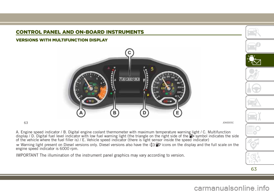
VERSIONS WITH MULTIFUNCTION DISPLAY
A. Engine speed indicator / B. Digital engine coolant thermometer with maximum temperature warning light / C. Multifunction
display / D. Digital fuel level indicator with low fuel warning light (the triangle on the right side of thesymbol indicates the side
of the vehicle where the fuel filler is) / E. Vehicle speed indicator (there is light sensor inside the speed indicator)
Warning light present on Diesel versions only. Diesel versions also have theicons on the display and the full scale on the
engine speed indicator is 6000 rpm.
IMPORTANT The illumination of the instrument panel graphics may vary according to version.
63J0A0005C
63
Page 66 of 356
64J0A0239C
64
KNOWING THE INSTRUMENT PANEL
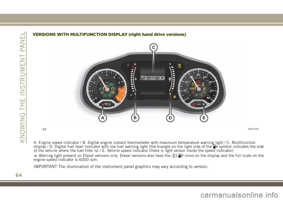
VERSIONS WITH MULTIFUNCTION DISPLAY (right hand drive versions)
A. Engine speed indicator / B. Digital engine coolant thermometer with maximum temperature warning light / C. Multifunction
display / D. Digital fuel level indicator with low fuel warning light (the triangle on the right side of thesymbol indicates the side
of the vehicle where the fuel filler is) / E. Vehicle speed indicator (there is light sensor inside the speed indicator)
Warning light present on Diesel versions only. Diesel versions also have theicons on the display and the full scale on the
engine speed indicator is 6000 rpm.
IMPORTANT The illumination of the instrument panel graphics may vary according to version.
Page 67 of 356
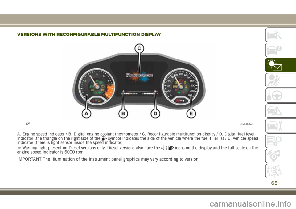
VERSIONS WITH RECONFIGURABLE MULTIFUNCTION DISPLAY
A. Engine speed indicator / B. Digital engine coolant thermometer / C. Reconfigurable multifunction display / D. Digital fuel level
indicator (the triangle on the right side of thesymbol indicates the side of the vehicle where the fuel filler is) / E. Vehicle speed
indicator (there is light sensor inside the speed indicator)
Warning light present on Diesel versions only. Diesel versions also have theicons on the display and the full scale on the
engine speed indicator is 6000 rpm.
IMPORTANT The illumination of the instrument panel graphics may vary according to version.
65J0A0006C
65