buttons JEEP RENEGADE 2023 Owners Manual
[x] Cancel search | Manufacturer: JEEP, Model Year: 2023, Model line: RENEGADE, Model: JEEP RENEGADE 2023Pages: 364, PDF Size: 18.65 MB
Page 24 of 364
22 GETTING TO KNOW YOUR VEHICLE
POWER DOOR LOCKS
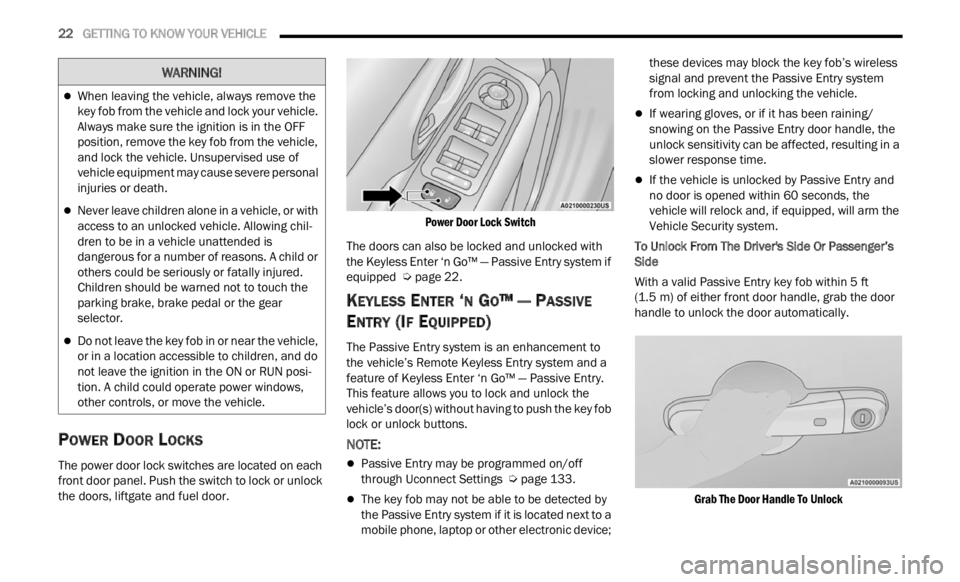
The power door lock switches are located on each
front door panel. Push the switch to lock or unlock
the doors, liftgate and fuel door.
Power Door Lock Switch
The doors can also be locked and unlocked with
the K e
yless Enter ‘n Go™ — Passive Entry system if
equipped Ú page 22.
KEYLESS ENTER ‘N GO™ — PASSIVE
E
NTRY (IF EQUIPPED)
The Passive Entry system is an enhancement to
the vehicle’s Remote Keyless Entry system and a
feature of Keyless Enter ‘n Go™ — Passive Entry.
This feature allows you to lock and unlock the
vehicle’s door(s) without having to push the key fob
lock or unlock buttons.
NOTE:
Passive Entry may be programmed on/off
through Uconnect Settings Ú page 133.
The key fob may not be able to be detected by
the Passive Entry system if it is located next to a
mobile phone, laptop or other electronic device; these devices may block the key fob’s wireless
signal and prevent the Passive Entry system
from locking and unlocking the vehicle.
If wearing gloves, or if it has been raining/
snowing on the Passive Entry door handle, the
unlock sensitivity can be affected, resulting in a
slower response time.
If the vehicle is unlocked by Passive Entry and
no door is opened within 60 seconds, the
vehicle will relock and, if equipped, will arm the
Vehicle Security system.
To Unlock From The Driver's Side Or Passenger’s
Side
Wit
h a valid Passive Entry key fob within 5 ft
(1.5 m)
of either front door handle, grab the door
handl e
to unlock the door automatically.
Grab The Door Handle To Unlock
When leaving the vehicle, always remove the
key fob from the vehicle and lock your vehicle.
Always make sure the ignition is in the OFF
position, remove the key fob from the vehicle,
and lock the vehicle. Unsupervised use of
vehicle equipment may cause severe personal
injuries or death.
Never leave children alone in a vehicle, or with
access to an unlocked vehicle. Allowing chil -
dren to be in a vehicle unattended is
d anger
ous for a number of reasons. A child or
others could be seriously or fatally injured.
Children should be warned not to touch the
parking brake, brake pedal or the gear
selector.
Do not leave the key fob in or near the vehicle,
or in a location accessible to children, and do
not leave the ignition in the ON or RUN posi -
tion. A child could operate power windows,
other c
ontrols, or move the vehicle.
WARNING!
Page 32 of 364
30 GETTING TO KNOW YOUR VEHICLE
Power Lumbar Adjustment— If Equipped
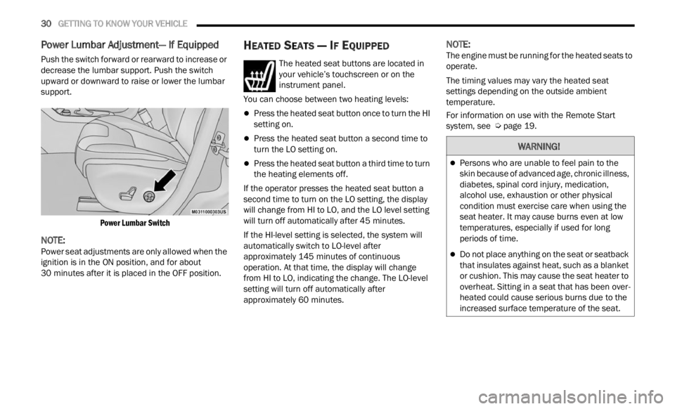
Push the switch forward or rearward to increase or
decrease the lumbar support. Push the switch
upward or downward to raise or lower the lumbar
support.
Power Lumbar Switch
NOTE:
Power seat adjustments are only allowed when the
ignit i
on is in the ON position, and for about
30 minutes after it is placed in the OFF position.
HEATED SEATS — IF EQUIPPED
The heated seat buttons are located in
your vehicle’s touchscreen or on the
instr u
ment panel.
You can choose between two heating levels:
Press the heated seat button once to turn the HI
setting on.
Press the heated seat button a second time to
turn the LO setting on.
Press the heated seat button a third time to turn
the heating elements off.
If the operator presses the heated seat button a
second
time to turn on the LO setting, the display
will change from HI to LO, and the LO level setting
will turn off automatically after 45 minutes.
If the HI-level setting is selected, the system will
a utomat
ically switch to LO-level after
approximately 145 minutes of continuous
operati
on. At that time, the display will change
from HI to LO, indicating the change. The LO-level
setting will turn off automatically after
approximately 60 minutes.
NOTE:
The engine must be running for the heated seats to
operat e
.
The timing values may vary the heated seat
settin
gs depending on the outside ambient
temperature.
For information on use with the Remote Start
syste m
, see Ú page 19.
WARNING!
Persons who are unable to feel pain to the
skin because of advanced age, chronic illness,
diabetes, spinal cord injury, medication,
alcohol use, exhaustion or other physical
condition must exercise care when using the
seat heater. It may cause burns even at low
temperatures, especially if used for long
periods of time.
Do not place anything on the seat or seatback
that insulates against heat, such as a blanket
or cushion. This may cause the seat heater to
overheat. Sitting in a seat that has been over
-
heated could cause serious burns due to the
i ncrea
sed surface temperature of the seat.
Page 34 of 364
32 GETTING TO KNOW YOUR VEHICLE
Front Head Restraints
Your vehicle is equipped with front driver and
passenger head restraints.
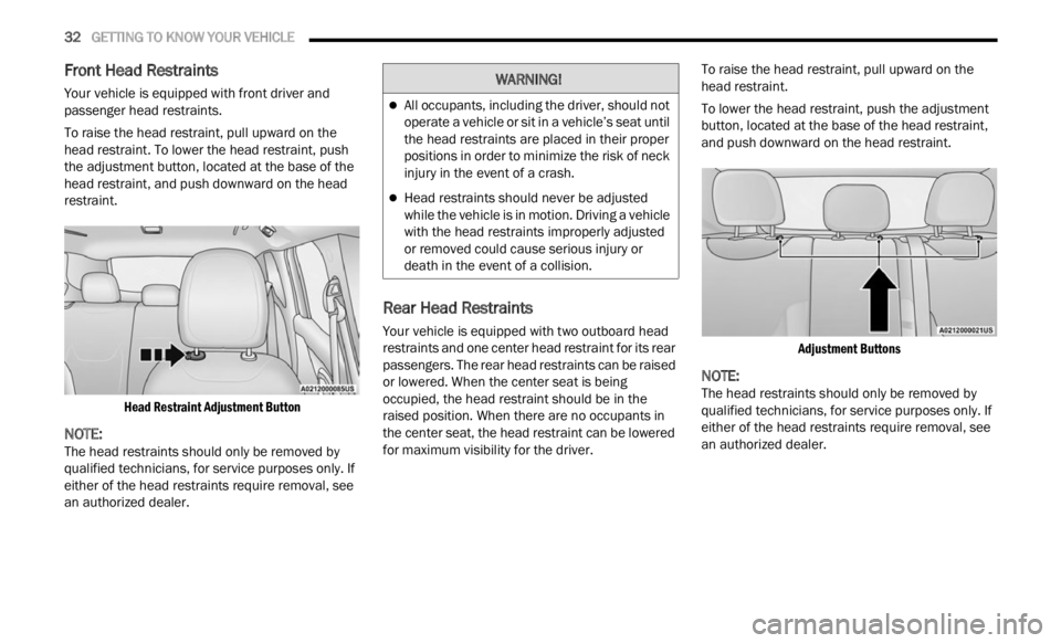
To raise the head restraint, pull upward on the
head r
estraint. To lower the head restraint, push
the adjustment button, located at the base of the
head restraint, and push downward on the head
restraint.
Head Restraint Adjustment Button
NOTE:
The head restraints should only be removed by
quali f
ied technicians, for service purposes only. If
either of the head restraints require removal, see
an authorized dealer.
Rear Head Restraints
Your vehicle is equipped with two outboard head
restraints and one center head restraint for its rear
passengers. The rear head restraints can be raised
or lowered. When the center seat is being
occupied, the head restraint should be in the
raised position. When there are no occupants in
the center seat, the head restraint can be lowered
for maximum visibility for the driver. To raise the head restraint, pull upward on the
head
r
estraint.
To lower the head restraint, push the adjustment
button,
located at the base of the head restraint,
and push downward on the head restraint.
Adjustment Buttons
NOTE:
The head restraints should only be removed by
quali f
ied technicians, for service purposes only. If
either of the head restraints require removal, see
an authorized dealer.
WARNING!
All occupants, including the driver, should not
operate a vehicle or sit in a vehicle’s seat until
the head restraints are placed in their proper
positions in order to minimize the risk of neck
injury in the event of a crash.
Head restraints should never be adjusted
while the vehicle is in motion. Driving a vehicle
with the head restraints improperly adjusted
or removed could cause serious injury or
death in the event of a collision.
Page 35 of 364
GETTING TO KNOW YOUR VEHICLE 33
UCONNECT VOICE RECOGNITION
INTRODUCING VOICE RECOGNITION
Start using Uconnect Voice Recognition with these
helpful quick tips. It provides the key Voice
Commands and tips you need to know to control
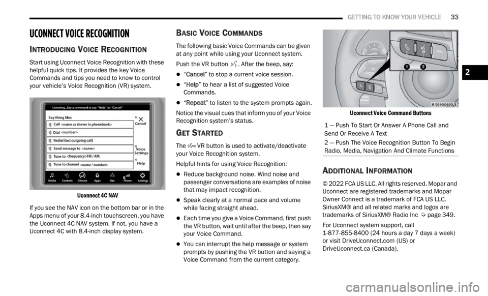
your vehicle’s Voice Recognition (VR) system.
Uconnect 4C NAV
If you see the NAV icon on the bottom bar or in the
Apps m
enu of your 8.4-inch touchscreen, you have
the Uconnect 4C NAV system. If not, you have a
Uconnect 4C with 8.4-inch display system.
BASIC VOICE COMMANDS
The following basic Voice Commands can be given
at any point while using your Uconnect system.
Push the VR button . After the beep, say:
“Cancel ” to stop a current voice session.
“Help ” to hear a list of suggested Voice
Commands.
“ Repeat ” to listen to the system prompts again.
Notice the visual cues that inform you of your Voice
Recogn i
tion system’s status.
GET STARTED
The VR button is used to activate/deactivate
your Voice Recognition system.
Helpful hints for using Voice Recognition:
Reduce background noise. Wind noise and
passenger conversations are examples of noise
that may impact recognition.
Speak clearly at a normal pace and volume
while facing straight ahead.
Each time you give a Voice Command, first push
the VR button, wait until after the beep, then say
your Voice Command.
You can interrupt the help message or system
prompts by pushing the VR button and saying a
Voice Command from the current category.
Uconnect Voice Command Buttons
ADDITIONAL INFORMATION
© 2022 FCA US LLC. All rights reserved. Mopar and
Uconnect are registered trademarks and Mopar
Owner Connect is a trademark of FCA US LLC.
SiriusXM® and all related marks and logos are
trademarks of SiriusXM® Radio Inc
Ú page 349.
For Uconnect system support, call
1-877 -
855-8400 (24 hours a day 7 days a week)
or visit DriveUconnect.com (US) or
DriveUconnect.ca (Canada).
1 — Push To Start Or Answer A Phone Call and
Send Or Receive A Text
2 — Push The Voice Recognition Button To Begin
Radio, Media, Navigation And Climate Functions
2
Page 42 of 364
40 GETTING TO KNOW YOUR VEHICLE
NOTE:
Before exiting the vehicle, make sure that the
interior lights are turned off. This will prevent the
battery from discharging once the doors are
closed.
If a light is left on, it will automatically be turned
off after approximately 15 minutes after the
ignit i
on is in the OFF position.
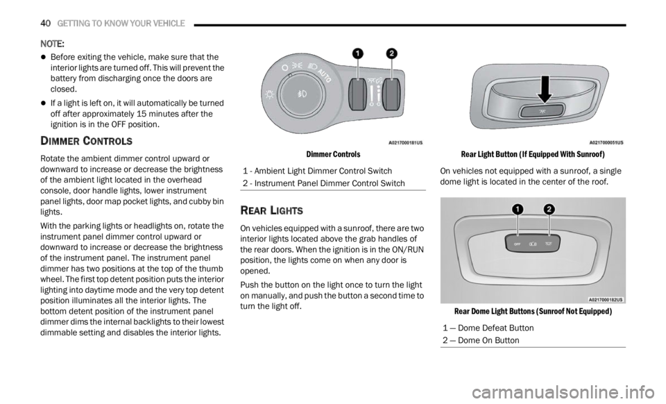
DIMMER CONTROLS
Rotate the ambient dimmer control upward or
downward to increase or decrease the brightness
of the ambient light located in the overhead
console, door handle lights, lower instrument
panel lights, door map pocket lights, and cubby bin
lights.
With the parking lights or headlights on, rotate the
instru
ment panel dimmer control upward or
downward to increase or decrease the brightness
of the instrument panel. The instrument panel
dimmer has two positions at the top of the thumb
wheel. The first top detent position puts the interior
lighting into daytime mode and the very top detent
position illuminates all the interior lights. The
bottom detent position of the instrument panel
dimmer dims the internal backlights to their lowest
dimmable setting and disables the interior lights.
Dimmer Controls
REAR LIGHTS
On vehicles equipped with a sunroof, there are two
interior lights located above the grab handles of
the rear doors. When the ignition is in the ON/RUN
position, the lights come on when any door is
opened.
Push the button on the light once to turn the light
on man
u
ally, and push the button a second time to
turn the light off.
Rear Light Button (If Equipped With Sunroof)
On vehicles not equipped with a sunroof, a single
dome l i
ght is located in the center of the roof.
Rear Dome Light Buttons (Sunroof Not Equipped)
1 - Ambient Light Dimmer Control Switch
2 - Instrument Panel Dimmer Control Switch
1 — Dome Defeat Button
2 — Dome On Button
Page 47 of 364
GETTING TO KNOW YOUR VEHICLE 45
(button on the touchscreen grayed out) if
conditions exist that could create fogging on the
inside of the windshield. The A/C can be
deselected manually without disturbing the mode
control selection. Continuous use of the
Recirculation mode may make the inside air stuffy
and window fogging may occur. Extended use of
this mode is not recommended. Recirculation
mode may automatically adjust to optimize
customer experience for warming, cooling,
dehumidification, etc.
In cold weather, use of Recirculation mode may
lead t
o excessive window fogging. The
Recirculation feature may be unavailable if
conditions exist that could create fogging on the
inside of the windshield.
AUTO Button
Press and release this button on the
touchscreen, or push the button on the
facep l
ate, to change the current setting.
The AUTO indicator illuminates when
AUTO is on. This feature automatically controls the
interior cabin temperature by adjusting distribution
and amount of airflow. Air Conditioning (A/C) may
be active during AUTO operation to improve
performance. Toggling this function will cause the
system to switch between manual override mode
and automatic modes Ú page 47.
Front Defrost Button
Press and release the touchscreen
button, or push and release the button
on the
faceplate, to change the current
airflow setting to Defrost mode. The Front
Defrost indicator illuminates when Front Defrost is
on. Air comes from the windshield and side window
demist outlets. When the defrost button is
selected, the blower level may increase. Use
Defrost mode with maximum temperature settings
for best windshield and side window defrosting
and defogging. When toggling the front defrost
mode button, the Climate Control system will
return to the previous setting.
Rear Defrost Button
Press and release the button on the
touchscreen, or push and release the
button
on the faceplate, to turn on the
rear window defroster and the heated
outside mirrors (if equipped). The Rear Defrost
indicator illuminates when the rear window
defroster is on. The rear window defroster
automatically turns off after 20 minutes.Driver And Passenger Up And Down
Buttons
These buttons provide the driver and passenger
with independent temperature control.
Push the red button on the faceplate or
touchscreen or press and slide the
temper
ature bar towards the red arrow
button on the touchscreen for warmer
temperature settings.
CAUTION!
Failure to follow these cautions can cause
damage to the heating elements:
Use care when washing the inside of the rear
window. Do not use abrasive window cleaners
on the interior surface of the window. Use a
soft cloth and a mild washing solution, wiping
parallel to the heating elements. Labels can
be peeled off after soaking with warm water.
Do not use scrapers, sharp instruments, or
abrasive window cleaners on the interior
surface of the window.
Keep all objects a safe distance from the
window.
2
Page 48 of 364
46 GETTING TO KNOW YOUR VEHICLE
Push the blue button on the faceplate or
touchscreen or press and slide the
tempe r
ature bar towards the blue arrow
button on the touchscreen for cooler
temperature settings.
SYNC Button
Press the SYNC button on the
touchscreen to toggle the Sync feature
on/off.
The SYNC indicator is illuminated
when SYNC is on. SYNC is used to
synchronize the passenger temperature setting
with the driver temperature setting. Changing the
passenger temperature setting while in SYNC will
automatically exit this feature.
NOTE:
The SYNC button is only available on the touch-
screen.
Blower Control
Blower Control is used to regulate the
amount of air forced through the Climate
Control
system. There are seven blower
speeds available. Adjusting the blower
will cause automatic mode to switch to manual
operation. The speeds can be selected using either
the blower control knob on the faceplate or the
buttons on the touchscreen. Faceplate
The blower speed increases as you turn the blower
c
ontrol
knob clockwise from the lowest blower
setting. The blower speed decreases as you turn
the blower control knob counterclockwise.
Touchscreen
Use the small blower icon to reduce the blower
setti n
g and the large blower icon to increase the
blower setting. Blower can also be selected by
pressing the blower bar area between the icons.
Mode Control
Select Mode by pressing one of the Mode
buttons on the touchscreen to change
the a i
rflow distribution mode. The airflow
distribution outlets are: instrument panel
outlets, floor outlets, defrost outlets, and demist
outlets.
Panel Mode
Air comes from the outlets in the
instrument panel. Each of these outlets
can b e
individually adjusted to direct the
flow of air. The air vanes of the center
outlets and outboard outlets can be moved up and
down or side to side to regulate airflow direction.
There is a shut-off wheel located below the air
vanes to shut off or adjust the amount of airflow
from these outlets.
Bi-Level Mode
Air comes from the instrument panel
outlets and floor outlets. A slight amount
of ai r
is directed through the defrost and
side window demister outlets.
NOTE:
Bi-Level mode is designed under comfort condi -
tions to provide cooler air out of the panel outlets
a nd w a
rmer air from the floor outlets.
Floor Mode
Air comes from the floor outlets. A slight
amount of air is directed through the
defrost
, side window demister outlets,
and panel outboard outlets.
Mix Mode
Air is directed through the floor, defrost,
and side window demister outlets. This
setti n
g works best in cold or snowy
conditions that require extra heat to the
windshield. This setting is good for maintaining
comfort while reducing moisture on the
windshield. A slight amount of air is also directed
through the panel outboard outlets.
Climate Control OFF Button
Press and release this button to turn the
Climate Control ON/OFF.
Page 67 of 364
GETTING TO KNOW YOUR INSTRUMENT PANEL 65
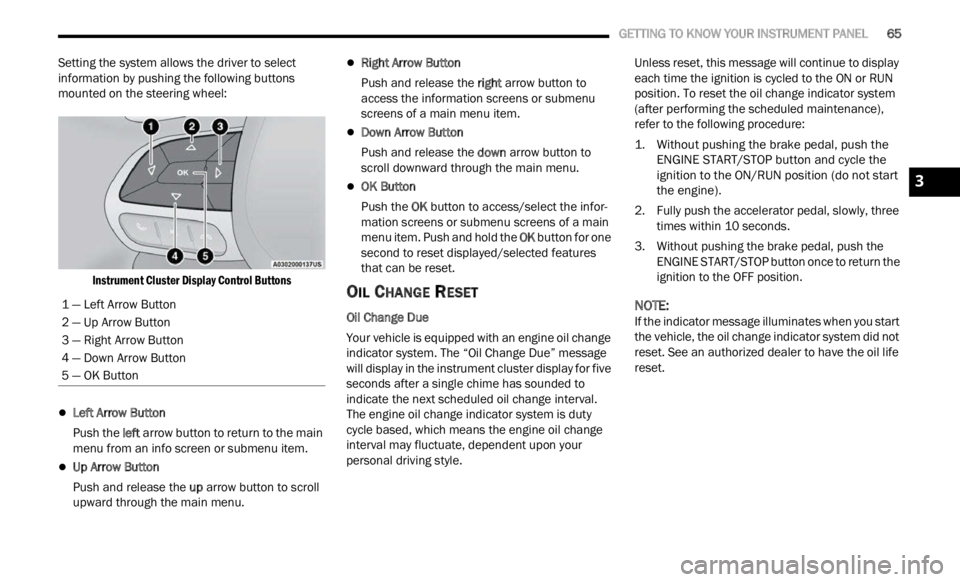
Setting the system allows the driver to select
information by pushing the following buttons
mounted on the steering wheel:
Instrument Cluster Display Control Buttons
Left Arrow Button
Push the l
eft a
rr
ow
button to return to the main
menu from an info screen or submenu item.
Up Arrow Button
Push and release the u
p a
rr
ow
button to scroll
upward through the main menu.
Right Arrow Button
Push and release the right
arrow button to
access the information screens or submenu
screens of a main menu item.
Down Arrow Button
Push and release the d
ow n
a r
r
ow button to
scroll downward through the main menu.
OK Button
Push the O
K b
ut
t
on to access/select the infor -
mation screens or submenu screens of a main
menu i
tem. Push and hold the OK button for one
second to reset displayed/selected features
that can be reset.
OIL CHANGE RESET
Oil Change Due
Your vehicle is equipped with an engine oil change
indic a
tor system. The “Oil Change Due” message
will display in the instrument cluster display for five
seconds after a single chime has sounded to
indicate the next scheduled oil change interval.
The engine oil change indicator system is duty
cycle based, which means the engine oil change
interval may fluctuate, dependent upon your
personal driving style. Unless reset, this message will continue to display
each
t
ime the ignition is cycled to the ON or RUN
position. To reset the oil change indicator system
(after performing the scheduled maintenance),
refer to the following procedure:
1. Without pushing the brake pedal, push the ENGI N
E START/STOP button and cycle the
ignition to the ON/RUN position (do not start
the engine).
2. Fully push the accelerator pedal, slowly, three times
within 10 seconds.
3. Without pushing the brake pedal, push the ENGIN
E START/STOP button once to return the
ignition to the OFF position.
NOTE:
If the indicator message illuminates when you start
the v e
hicle, the oil change indicator system did not
reset. See an authorized dealer to have the oil life
reset.
1 — Left Arrow Button
2 — Up Arrow Button
3 — Right Arrow Button
4 — Down Arrow Button
5 — OK Button
3
Page 93 of 364
STARTING AND OPERATING 91
FOUR-WHEEL DRIVE (4WD)
The four-wheel drive (4WD) is fully automatic in
normal driving mode.
NOTE:
It is not possible to carry out the change of mode
when t
he vehicle exceeds the speed of 75 mph
( 1
2 0
k m
/h).
Enabling Four-Wheel Drive (4WD)
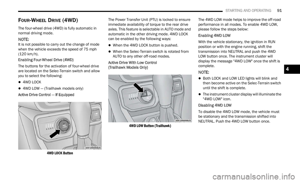
The buttons for the activation of four-wheel drive
a re l oc
ated on the Selec-Terrain switch and allow
you to select the following:
4WD LOCK
4WD LOW — (Trailhawk models only)
Active Drive Control — If Equipped
4WD LOCK Button
The Power Transfer Unit (PTU) is locked to ensure
immed
i
ate availability of torque to the rear drive
axles. This feature is selectable in AUTO mode and
automatic in the other driving mode. 4WD LOCK
can be enabled by the following ways:
When the 4WD LOCK button is pushed.
When the Selec-Terrain switch is rotated from
AUTO to any other off-road modes.
Active Drive With Low Control
(Trailhawk Models Only)
4WD LOW Button (Trailhawk)
The 4WD LOW mode helps to improve the off-road
perform
ance in all modes. To enable 4WD LOW,
please follow the steps below:
Enabling 4WD LOW
With the vehicle stationary, the ignition in RUN
p osition
or with the engine running, shift the
transmission into NEUTRAL and push the 4WD
LOW button once. The instrument cluster will
display the message "4WD LOW" once the shift is
complete.
NOTE:
Both LOCK and LOW LED lights will blink and
then become active on the Selec-Terrain switch
until the shift is complete.
The instrument cluster display will illuminate the
"4WD LOW" icon.
Disabling 4WD LOW
To disable the 4WD LOW mode, the vehicle must
be st a
tionary and the transmission shifted into
NEUTRAL. Push the 4WD LOW button once.
4
Page 97 of 364
STARTING AND OPERATING 95
TO MANUALLY TURN OFF THE STOP/
S
TART SYSTEM
Stop/Start OFF Switch
Push the Stop/Start OFF switch (located on the
center
console). The light on the switch will
illuminate. The “STOP/START OFF” message will
appear in the instrument cluster display and the
Autostop mode will be disabled Ú page 64.
NOTE:
The Stop/Start system will reset itself back to an
ON con d
ition every time the ignition is turned off
and back on.
TO MANUALLY TURN ON THE STOP/
S
TART SYSTEM
Push the Stop/Start OFF switch (located on the
switch bank). The light on the switch will turn off.
SYSTEM MALFUNCTION
If there is a malfunction in the Stop/Start system,
the system will not shut down the engine. A
“SERVICE STOP/START SYSTEM” message and a
yellow Stop/Start telltale will appear in the
instrument cluster display Ú page 64.
If the “SERVICE STOP/START SYSTEM” message
appea r
s in the instrument cluster display, have the
system checked by an authorized dealer.
CRUISE CONTROL SYSTEMS — IF EQUIPPED
Your vehicle may be equipped with the Cruise
Control system, or the Adaptive Cruise Control
(ACC) system:
Cruise Control for cruising at a constant preset
speed.
Adaptive Cruise Control (ACC) for maintaining a
set distance between you and the vehicle ahead
using Fixed Speed Cruise Control to automati -
cally adjust the preset speed.
NOTE:
In vehicles equipped with ACC, if ACC is not
enabled, Fixed Speed Cruise Control will not
detect vehicles directly ahead of you. Always be
aware of the feature selected.
Only one Cruise Control feature can operate at a
time. For example, if Fixed Speed Cruise Control is enabled, Adaptive Cruise Control will be
unavailable, and vice versa.
CRUISE CONTROL
When engaged, the Cruise Control takes over
accelerator operations at speeds greater than
20
mph (32 km/h).
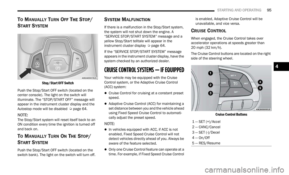
The Cruise Control buttons are located on the right
side of
the steering wheel.
Cruise Control Buttons
1 — SET (+)/Accel
2 — CANC/Cancel
3 — SET (-)/Decel
4 — On/Off
5 — RES/Resume
4