display JEEP WAGONEER 2023 Owner's Manual
[x] Cancel search | Manufacturer: JEEP, Model Year: 2023, Model line: WAGONEER, Model: JEEP WAGONEER 2023Pages: 396, PDF Size: 15.17 MB
Page 72 of 396
70GETTING TO KNOW YOUR VEHICLE
AUTO BUTTON
Push the AUTO button below the rear climate
control display, or if equipped, press and
release the AUTO button on the Rear Comfort
And Convenience Display touchscreen to
control the rear passenger area’s temperature by
automatically adjusting distribution and amount of airflow.
Performing this function will cause the system to switch
between manual mode and automatic modes
Úpage 71.
REAR TEMPERATURE CONTROL
Push the Up or Down buttons near the rear climate control
display, or if equipped, press the Up or Down arrow
buttons on the Rear Comfort And Convenience Display
touchscreen to control the rear passenger’s temperature.
NOTE:If equipped with a Four-Zone ATC system, the left and right
sides of the rear passenger zones can be adjusted sepa -
rately.
Push the Up arrow hard button, or press and
release, or slide the temperature bar on the
touchscreen towards the red arrow button on
the touchscreen for warmer temperature
settings.
Push the Down arrow hard button, or press and
release, or slide the temperature bar on the
touchscreen towards the blue arrow button on
the touchscreen for cooler temperature
settings.
REAR BLOWER CONTROL
Blower Control is used to regulate the amount
of air forced through the Climate Control
system. There are several blower speeds
available. The speeds can be selected using
the blower control buttons near the rear climate control
display, or if equipped, on the Rear Comfort And
Convenience Display touchscreen.
Use the blower button with the down arrow, or small
blower icon on the touchscreen to reduce the blower
setting. Use the blower button with the up arrow, or the
large blower icon on the touchscreen to increase the
blower setting.
NOTE:Blower speed can also be selected by pressing the
numbered blower speed on the touchscreen bar area
between the blower icons.
REAR MODE CONTROL
Pushing the Mode button below the rear
climate control display, located on the rear of
the center console, will cycle through the three
rear mode control options for airflow
distribution. These options are: Face, Face/Feet, and
Feet.
Mode Control From The Rear Comfort And Convenience
Display
If equipped with the Rear Comfort And Convenience
display, two airflow distribution modes can be selected
on/off from the display by individually by pressing the icons on the touchscreen for up to three combinations of
airflow. The icons on the screen will illuminate when
selected, and turn off when deselected.
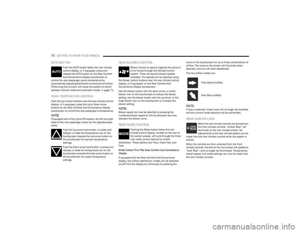
The two airflow modes are:
NOTE:If Auto is selected, these icons will no longer be available
and the current mode selection will be overwritten.
REAR CLIMATE LOCK
When the rear climate controls are locked from
the front climate controls, “Unlock Rear” will
illuminate on the rear climate screen. No
adjustments to the rear climate system can be
made from the rear climate controls while the system is
locked.
When the controls are then unlocked from the front
climate controls, the text on the rear screen will update to
“Lock Rear”, and no longer be illuminated. Temperature,
blower speed, and mode settings can now be made from
the rear climate controls.
Face (panel outlets)
Feet (floor outlets)
23_WS_OM_EN_USC_t.book Page 70
Page 73 of 396
GETTING TO KNOW YOUR VEHICLE71
REAR CLIMATE CONTROL OFF
To turn the rear climate controls off, push the
OFF button below the rear climate control
display, or if equipped, press and release the
OFF button on the Rear Comfort And
Convenience Display touchscreen, near the blower
buttons.
AUTOMATIC TEMPERATURE CONTROL
(ATC)
Automatic Operation
1. Push the AUTO button on the front climate control
display, and the word “AUTO” will illuminate along
with two temperatures for the driver and front
passenger. The system will then automatically
regulate the amount of airflow.
2. Adjust the temperature you would like the system to maintain, by adjusting the driver, passenger, and rear
temperatures. Once the desired temperature is
displayed, the system will achieve, and automatically
maintain, that comfort level.
3. When the system is set up for your comfort level, it is not necessary to change the settings. You will
experience the greatest efficiency by simply allowing
the system to function automatically.
NOTE:It is not necessary to move the temperature settings. The
system automatically adjusts the temperature, mode, and
fan speed to provide comfort as quickly as possible. To provide you with maximum comfort in the automatic
mode during cold start-ups, the blower fan will remain on
low until the engine warms up. The fan will engage
immediately if the Defrost mode is selected, or by
changing the front blower setting.
Manual Operation Override
This system offers a full complement of manual override
features. The AUTO symbol in the front climate control
display will no longer be illuminated when the system is
being used in the manual mode.
NOTE:The system will not automatically sense the presence of
fog, mist or ice on the windshield. Defrost mode must be
manually selected to clear the windshield and side glass.
CLIMATE VOICE RECOGNITION
Adjust vehicle temperatures hands-free and keep
everyone comfortable while you keep moving ahead (If
vehicle is equipped with climate control).
Push the VR/Phone button . After the beep, say one of
the following commands:
“Set the driver temperature to 70 degrees”
“Set the passenger temperature to 70 degrees”
Did You Know: Voice Command for Climate may only be
used to adjust the interior temperature of your vehicle.
Voice Command will not work to adjust the heated seats
or steering wheel if equipped.
OPERATING TIPS
Refer to the chart at the end of this section for suggested
control settings for various weather conditions.
Summer Operation
The engine cooling system must be protected with a
high-quality antifreeze coolant to provide proper corrosion
protection and to protect against engine overheating. OAT
coolant (conforming to MS.90032) is recommended.
Winter Operation
To ensure the best possible heater and defroster
performance, make sure the engine cooling system is
functioning properly and the proper amount, type, and
concentration of coolant is used. Use of the Air
Recirculation mode during Winter months is not
recommended, because it may cause window fogging.
Vacation/Storage
For information on maintaining the Climate Control system
when the vehicle is being stored for an extended period of
time, see
Úpage 368.
CAUTION!
Interior air enters the Rear Climate Control system
through an intake grille, located in the right side trim
panel behind the third row seats. The heater outlets are
located in the right side trim panel, just behind the rear
doors. Do not block or place objects directly in front of
the inlet grille or heater outlets. The electrical system
could overload causing damage to the blower motor.
2
23_WS_OM_EN_USC_t.book Page 71
Page 76 of 396
74GETTING TO KNOW YOUR VEHICLE
Rear Full Center Console — If Equipped
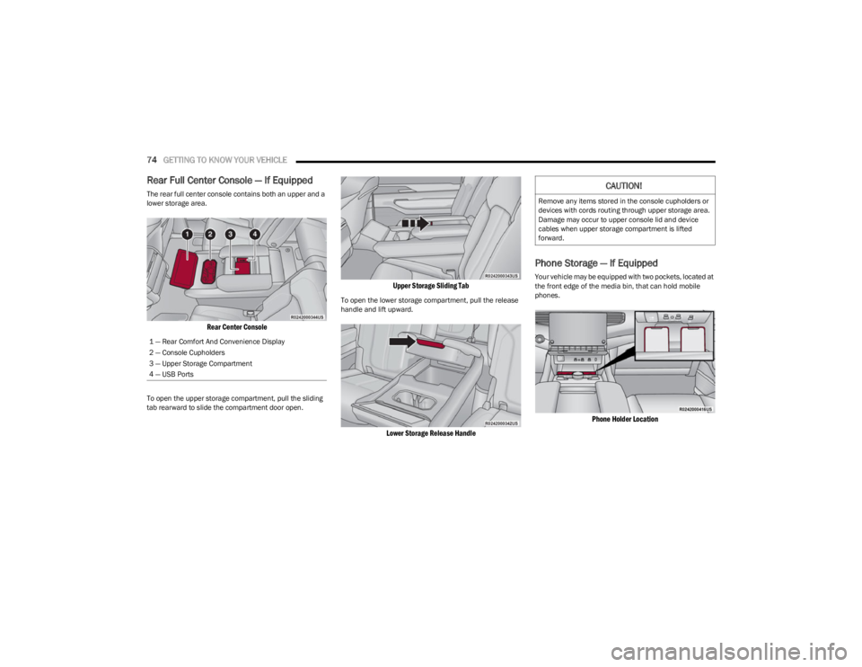
The rear full center console contains both an upper and a
lower storage area.
Rear Center Console
To open the upper storage compartment, pull the sliding
tab rearward to slide the compartment door open.
Upper Storage Sliding Tab
To open the lower storage compartment, pull the release
handle and lift upward.
Lower Storage Release Handle
Phone Storage — If Equipped
Your vehicle may be equipped with two pockets, located at
the front edge of the media bin, that can hold mobile
phones.
Phone Holder Location
1 — Rear Comfort And Convenience Display
2 — Console Cupholders
3 — Upper Storage Compartment
4 — USB Ports
CAUTION!
Remove any items stored in the console cupholders or
devices with cords routing through upper storage area.
Damage may occur to upper console lid and device
cables when upper storage compartment is lifted
forward.
23_WS_OM_EN_USC_t.book Page 74
Page 79 of 396
GETTING TO KNOW YOUR VEHICLE77
NOTE:Two devices can be plugged in at the same time, and both
ports will provide charging capabilities. Only one port can
transfer data to the system at a time.
For example, if a device is plugged into the Type A USB port
and another device is plugged into the Type C USB port, a
message will appear and allow you to select which device
to use.
The following scenarios are listed as follows when a
non-phone device is plugged into the smaller and larger
USB ports, and when a phone device is plugged into the
smaller and larger USB ports:
“A new device is now connected. Previous connection
was lost.”
“(Phone Name) now connected. Previous connection
was lost.”
“Another device is in use through the same USB port.
Please disconnect the first device to use the second
device.”
Plugging in a phone or another USB device may cause the
connection to a previous device to be lost.Connecting AUX Or The External USB
Device
Use a connection cable to connect an external USB device
to the vehicle’s USB port, or use an auxiliary cable to
connect a device to the vehicle’s AUX port. These ports are
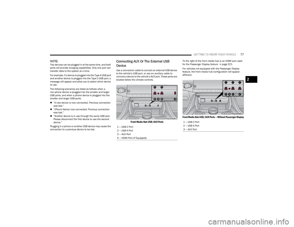
located below the climate controls.
Front Media Hub USB/AUX Ports
To the right of the front media hub is an HDMI port used
for the Passenger Display feature Úpage 221.
For vehicles not equipped with the Passenger Display
feature, the front media hub configuration will appear
different.
Front Media Hub USB/AUX Ports — Without Passenger Display
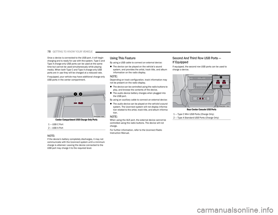
1 — USB C Port
2 — USB A Port
3 — AUX Port
4 — HDMI Port (If Equipped)
1 — USB C Port
2 — USB A Port
3 — AUX Port
2
23_WS_OM_EN_USC_t.book Page 77
Page 80 of 396
78GETTING TO KNOW YOUR VEHICLE
Once a device is connected to the USB port, it will begin
charging and is ready for use with the system. Type C and
Type A charge-only USB ports can be used at the same
time but cannot be used simultaneously while playing
media. When both Type C and Type A charge-only USB
ports are in use they will be charged at a reduced rate.
If equipped, your vehicle may have additional charge-only
USB ports in the center compartment.
Center Compartment USB Charge-Only Ports
NOTE:If the device’s battery completely discharges, it may not
communicate with the Uconnect system until a minimum
charge is attained. Leaving the device connected to the
USB port may charge it to the required level.
Using This Feature
By using a USB cable to connect an external device:
The device can be played on the vehicle’s sound
system, and provides the artist, track title, and album
information on the radio display.
NOTE:Depending on track configuration, track information may
not be present on the radio display.
The device can be controlled using the radio buttons to
play, and browse the contents of the device.
The audio device battery charges when plugged into
the USB port.
By using an auxiliary cable to connect an external device:
The audio device can be played on the vehicle’s sound
system. The Uconnect system will not display informa -
tion related to the artist, track title, and album informa -
tion.
NOTE:When using the AUX port, the external device cannot be
controlled using the radio buttons. The device will not
charge.
For further information, refer to the Uconnect Radio
Instruction Manual.
Second And Third Row USB Ports —
If Equipped
If equipped, the second row USB ports can be used to
charge a device.
Rear Center Console USB Ports
1 — USB C Port
2 — USB A Port
1 — Type C Mini USB Ports (Charge Only)
2 — Type A Standard USB Ports (Charge Only)
23_WS_OM_EN_USC_t.book Page 78
Page 81 of 396
GETTING TO KNOW YOUR VEHICLE79
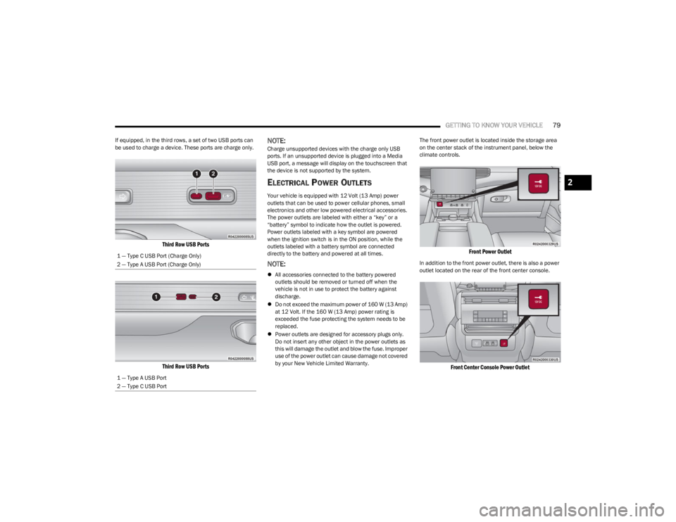
If equipped, in the third rows, a set of two USB ports can
be used to charge a device. These ports are charge only.
Third Row USB Ports
Third Row USB Ports
NOTE:Charge unsupported devices with the charge only USB
ports. If an unsupported device is plugged into a Media
USB port, a message will display on the touchscreen that
the device is not supported by the system.
ELECTRICAL POWER OUTLETS
Your vehicle is equipped with 12 Volt (13 Amp) power
outlets that can be used to power cellular phones, small
electronics and other low powered electrical accessories.
The power outlets are labeled with either a “key” or a
“battery” symbol to indicate how the outlet is powered.
Power outlets labeled with a key symbol are powered
when the ignition switch is in the ON position, while the
outlets labeled with a battery symbol are connected
directly to the battery and powered at all times.
NOTE:
All accessories connected to the battery powered
outlets should be removed or turned off when the
vehicle is not in use to protect the battery against
discharge.
Do not exceed the maximum power of 160 W (13 Amp)
at 12 Volt. If the 160 W (13 Amp) power rating is
exceeded the fuse protecting the system needs to be
replaced.
Power outlets are designed for accessory plugs only.
Do not insert any other object in the power outlets as
this will damage the outlet and blow the fuse. Improper
use of the power outlet can cause damage not covered
by your New Vehicle Limited Warranty. The front power outlet is located inside the storage area
on the center stack of the instrument panel, below the
climate controls.
Front Power Outlet
In addition to the front power outlet, there is also a power
outlet located on the rear of the front center console.
Front Center Console Power Outlet
1 — Type C USB Port (Charge Only)
2 — Type A USB Port (Charge Only)
1 — Type A USB Port
2 — Type C USB Port
2
23_WS_OM_EN_USC_t.book Page 79
Page 98 of 396
96
GETTING TO KNOW YOUR INSTRUMENT PANEL
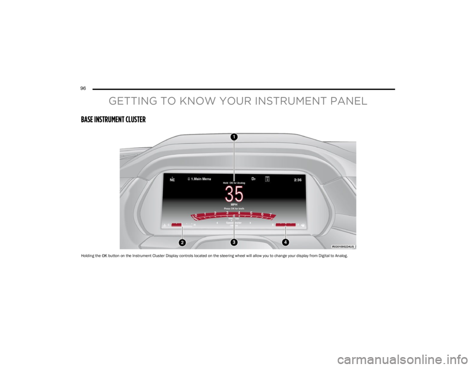
BASE INSTRUMENT CLUSTER
Holding the OK button on the Instrument Cluster Display controls located on the steering wheel will allow you to change your display from Digital to Analog.
23_WS_OM_EN_USC_t.book Page 96
Page 100 of 396
98GETTING TO KNOW YOUR INSTRUMENT PANEL
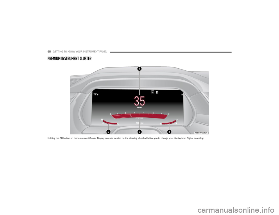
PREMIUM INSTRUMENT CLUSTER
Holding the OK button on the Instrument Cluster Display controls located on the steering wheel will allow you to change your display from Digital to Analog.
23_WS_OM_EN_USC_t.book Page 98
Page 101 of 396
GETTING TO KNOW YOUR INSTRUMENT PANEL99
INSTRUMENT CLUSTER DESCRIPTIONS
1. Speedometer
Indicates vehicle speed.
2. Temperature Gauge The temperature gauge shows engine coolant
temperature. Any reading within the normal range
indicates that the engine cooling system is oper -
ating satisfactorily.
The pointer will likely indicate a higher tempera -
ture when driving in hot weather, up mountain
grades, or when towing a trailer. It should not be
allowed to exceed the upper limits of the normal
operating range. 3. Tachometer
Indicates the engine speed in revolutions per
minute (RPM x 1000).
4. Fuel Gauge The pointer shows the level of fuel in the fuel tank
when the Keyless Push Button Ignition is in the
ON/RUN position.
The fuel pump symbol points to the
side of the vehicle where the fuel door
is located.
NOTE:The Instrument Cluster Warning Indicators will illuminate
briefly for a bulb check when the ignition is first cycled.
INSTRUMENT CLUSTER DISPLAY
Depending on your vehicles trim level, features and
options may vary.
Your vehicle is equipped with an instrument cluster
display, which offers useful information to the driver. With
the ignition in the OFF mode, opening/closing of a door will
activate the display for viewing, and display the total miles,
or kilometers, in the odometer. Your instrument cluster
display is designed to display important information about
your vehicle’s systems and features. Using a driver interactive display located on the
instrument panel, your instrument cluster display can
show how systems are working and give you warnings
when they are not. The steering wheel mounted controls
allow you to scroll through the main menus and
submenus. You can access the specific information you
want and make selections and adjustments.
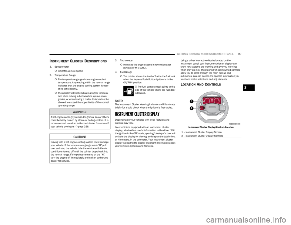
LOCATION AND CONTROLS
Instrument Cluster Display/Controls Location
WARNING!
A hot engine cooling system is dangerous. You or others
could be badly burned by steam or boiling coolant. It is
recommended to call an authorized dealer for service if
your vehicle overheats
Úpage 326.
CAUTION!
Driving with a hot engine cooling system could damage
your vehicle. If the temperature gauge reads “H” pull
over and stop the vehicle. Idle the vehicle with the air
conditioner turned off until the pointer drops back into
the normal range. If the pointer remains on the “H”,
turn the engine off immediately and call an authorized
dealer for service.
1 – Instrument Cluster Display Screen
2 – Instrument Cluster Display Controls
3
23_WS_OM_EN_USC_t.book Page 99
Page 102 of 396
100GETTING TO KNOW YOUR INSTRUMENT PANEL
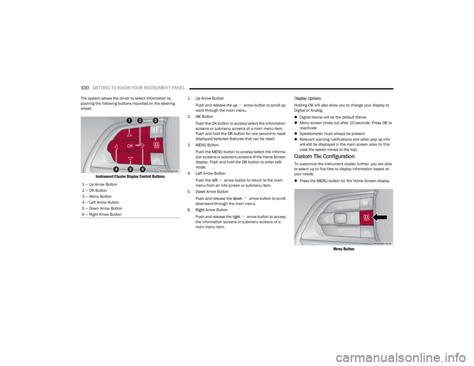
The system allows the driver to select information by
pushing the following buttons mounted on the steering
wheel:
Instrument Cluster Display Control Buttons
1.
Up
Arrow Button
Push and release the up arrow button to scroll up -
ward through the main menu.
2. OK Button
Push the OK button to access/select the information
screens or submenu screens of a main menu item.
Push and hold the OK button for one second to reset
displayed/selected features that can be reset.
3. MENU Button
Push the MENU button to access/select the informa -
tion screens or submenu screens of the Home Screen
display. Push and hold the OK button to enter edit
mode.
4. Left Arrow Button
Push the left arrow button to return to the main
menu from an info screen or submenu item.
5. Down Arrow Button
Push and release the down arrow button to scroll
downward through the main menu.
6. Right Arrow Button
Push and release the right arrow button to access
the information screens or submenu screens of a
main menu item. Display Options
Holding
OK will also allow you to change your display to
Digital or Analog.
Digital theme will be the default theme
Menu screen times out after 10 seconds. Press OK to
reactivate
Speedometer must always be present
Relevant warning notifications and other pop-up info
will still be displayed in the main screen area (In this
case the speed moves to the top)
Custom Tile Configuration
To customize the instrument cluster further, you are able
to select up to five tiles to display information based on
your needs.
Press the MENU button for the Home Screen display
Menu Button
1 — Up Arrow Button
2 — OK Button
3 — Menu Button
4 — Left Arrow Button
5 — Down Arrow Button
6 — Right Arrow Button
23_WS_OM_EN_USC_t.book Page 100