ECO mode JEEP WAGONEER 2023 Service Manual
[x] Cancel search | Manufacturer: JEEP, Model Year: 2023, Model line: WAGONEER, Model: JEEP WAGONEER 2023Pages: 396, PDF Size: 15.17 MB
Page 172 of 396
170STARTING AND OPERATING
NOTE:
The Active Lane Management system operates with
similar behavior for a right lane departure.
If the turn signal is activated, and the vehicle begins to
depart the lane at the same time the Blind Spot Moni -
toring (BSM) system detects another vehicle in the
BSM zones, the system will provide haptic steering
wheel vibration and/or steering assist torque (if
programmed in Uconnect Settings).
CHANGING ACTIVE LANE MANAGEMENT
S
TATUS
Configurable settings for the Active Lane Management
system are available within the Uconnect system
Úpage 197.
Selectable Warning Types:
Vibration Only
Steering Assist Only
Vibration And Steering Assist
Other configurable settings for this system are for the
intensity of the vibration (high/med/low), steering assist
strength (hi/med/low), and the warning zone sensitivity
(early/medium/late).
NOTE:
The system will not apply vibration and/or steering
assist to the steering wheel whenever a safety system
engages (Anti-Lock Brakes, Traction Control System,
Electronic Stability Control, Forward Collision Warning,
etc.).
The Blind Spot Monitoring system will be forced on
when the ALM system is enabled.
The ALM system will be suppressed when the Active
Driving Assist system (if equipped) is engaged.
PARKVIEW REAR BACK UP CAMERA
Your vehicle is equipped with the ParkView Rear Back Up
Camera that allows you to see an on-screen image of the
rear surroundings of your vehicle whenever the gear
selector is put into REVERSE. The image will be displayed
on the Navigation/Multimedia radio display screen along
with a caution note to “Check Entire Surroundings” across
the top of the screen. After five seconds this note will
disappear. The ParkView camera is located on the rear of
the vehicle above the rear license plate.
When the vehicle is shifted out of REVERSE with camera
delay turned off, the rear camera mode is exited and the
previous screen appears.
Manual Activation Of The Back Up Camera
1. Press the Vehicle button located on the bottom of
the Uconnect display and then select the Controls
menu.
2. Press the Back Up Camera icon to turn the Rear View Camera system on.
NOTE:
The Rear View camera can also be turned on manually
through the Apps menu within the Uconnect system.
The ParkView Rear Back Up Camera has program -
mable modes of operation that may be selected
through the Uconnect system
Úpage 197. When the vehicle is shifted out of REVERSE with camera
delay turned off, the rear camera mode is exited and the
previous screen appears. When the vehicle is shifted out
of REVERSE with camera delay turned on, the camera
image will continue to be displayed for up to 10 seconds
unless the following conditions occur: the vehicle speed
exceeds 8 mph (13 km/h), the vehicle is shifted into
PARK, the vehicle’s ignition is placed in the OFF position,
or the touchscreen X button to disable the display of the
Rear View Camera is pressed.
When enabled, active guidelines are overlaid on the image
to illustrate the width of the vehicle and its projected back
up path based on the steering wheel position. A dashed
center line overlay indicates the center of the vehicle to
assist with parking or aligning to a hitch/receiver.
Different colored zones indicate the distance to the rear of
the vehicle.
The following table shows the approximate distances for
each zone:
Zone Distance To The Rear Of The
Vehicle
Red 0 - 1 ft
(0 - 30 cm)
Yellow 1 ft - 6.5 ft
(30 cm - 2 m)
Green 6.5 ft or greater
(2 m or greater)
23_WS_OM_EN_USC_t.book Page 170
Page 177 of 396
STARTING AND OPERATING175
SURROUND VIEW CAMERA SYSTEM —
IF EQUIPPED
Your vehicle may be equipped with the Surround View
Camera system that allows you to see an on-screen image
of the surroundings and Top View of your vehicle whenever
the gear selector is put into REVERSE or a different view is
selected through the touchscreen buttons. The Top View
of the vehicle will show which doors are open. The image
will be displayed on the touchscreen display along with a
caution note “Check Entire Surroundings” across the top
of the screen. After five seconds, this note will disappear.
The Surround View Camera system is comprised of four
sequential cameras located in the front grille, rear liftgate
and side mirrors.
NOTE:The Surround View Camera system has programmable
settings that may be selected through the Uconnect
system
Úpage 197.
Press this button on the touchscreen to enter
the Surround View Camera menu in the
Uconnect system. When the vehicle is shifted into REVERSE, the
Rear View or Top View is the default view of the system.
When the vehicle is shifted out of REVERSE with camera
delay turned on, the camera image will continue to be
displayed for up to 10 seconds unless the vehicle speed
exceeds
8 mph (13 km/h, the vehicle is shifted into PARK
or the ignition is placed in the OFF position. There is a
touchscreen X button to disable the display of the camera
image.
When the vehicle is shifted out of REVERSE with camera
delay turned off, the Surround View Camera mode is
exited and the last known screen appears again.
When enabled, active guidelines are overlaid on the image
to illustrate the width of the vehicle, including the side
view mirrors and its projected back up path based on the
steering wheel position.
Different colored zones indicate the distance to the rear of
the vehicle.
The following table shows the approximate distances for
each zone:
Modes Of Operation
Manual activation of the Surround View Camera is
selected by pressing the Surround View Camera button
located in the Controls menu within the Uconnect system.
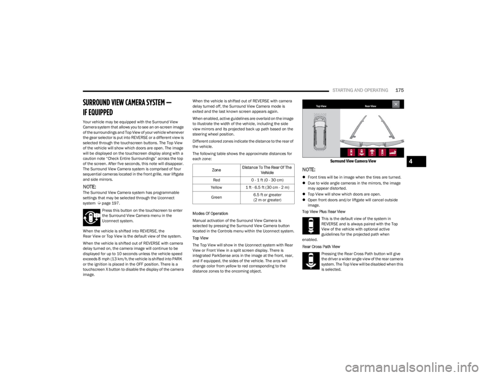
Top View
The Top View will show in the Uconnect system with Rear
View or Front View in a split screen display. There is
integrated ParkSense arcs in the image at the front, rear,
and if equipped, the sides of the vehicle. The arcs will
change color from yellow to red corresponding to the
distance zones to the oncoming object.
Surround View Camera View
NOTE:
Front tires will be in image when the tires are turned.
Due to wide angle cameras in the mirrors, the image
may appear distorted.
Top View will show which doors are open.
Open front doors and/or liftgate will cancel outside
image.
Top View Plus Rear View
This is the default view of the system in
REVERSE and is always paired with the Top
View of the vehicle with optional active
guidelines for the projected path when
enabled.
Rear Cross Path View
Pressing the Rear Cross Path button will give
the driver a wider angle view of the rear camera
system. The Top View will be disabled when this
is selected.
Zone Distance To The Rear Of The
Vehicle
Red 0 - 1 ft (0 - 30 cm)
Yellow 1 ft - 6.5 ft (30 cm - 2 m)
Green 6.5 ft or greater
(2 m or greater)
4
23_WS_OM_EN_USC_t.book Page 175
Page 182 of 396
180STARTING AND OPERATING
RECOMMENDED DISTRIBUTION HITCH
ADJUSTMENT — QUADRA-LIFT AIR SUSPEN -
SION EQUIPPED VEHICLES
1. Verify that the vehicle is at the Normal Ride Height.
NOTE:The vehicle must remain in the RUN position with all doors
closed while attaching a trailer for proper leveling of the air
suspension system.
2. Position the vehicle on a level surface in preparation to connect to the trailer (do not connect the trailer).
3. For vehicles equipped with Quadra-Lift air suspension, use the touchscreen radio settings to
enable Tire/Jack mode. Tire/Jack mode will be
canceled and the procedure must be restarted if the
vehicle is driven at speeds above 5 mph (8 km/h).
When towing, the automatic Entry/Exit feature may
be disabled through the Uconnect Touchscreen Radio
to prevent vehicle and trailer movement when gear
selector is moved to PARK.
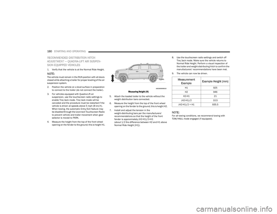
4. Measure the height from the top of the front wheel opening on the fender to the ground; this is height H1.
Measuring Height (H)
5. Attach the loaded trailer to the vehicle without the weight distribution bars connected.
6. Measure the height from the top of the front wheel opening on the fender to the ground; this is height H2.
7. Install and adjust the tension in the weight-distributing bars per the manufacturers’
recommendations so that the height of the front
fender is approximately (H2-H1)/2+H1
(about 1/2 the difference between H2 and H1 above
Normal Ride Height [H1]). 8. Use the touchscreen radio settings and switch off
Tire/Jack mode. Make sure the vehicle returns to
Normal Ride Height. Perform a visual inspection of
the trailer and weight-distributing hitch to confirm the
manufacturers’ recommendations have been met.
9. The vehicle can now be driven.
NOTE:For all towing conditions, we recommend towing with
TOW/HAUL mode engaged (if equipped).
Measurement Example Example Height (mm)
H1
925
H2 946
H2-H1 21
(H2-H1)/2 10.5
(H2-H1)/2 + H1 935.5
23_WS_OM_EN_USC_t.book Page 180
Page 183 of 396
STARTING AND OPERATING181
RECOMMENDED DISTRIBUTION HITCH
ADJUSTMENT — NON-AIR SUSPENSION
EQUIPPED VEHICLES
1. Verify that the vehicle is at the normal ride height.
2. Position the vehicle on a level surface in preparation
to connect to the trailer (do not connect the trailer).
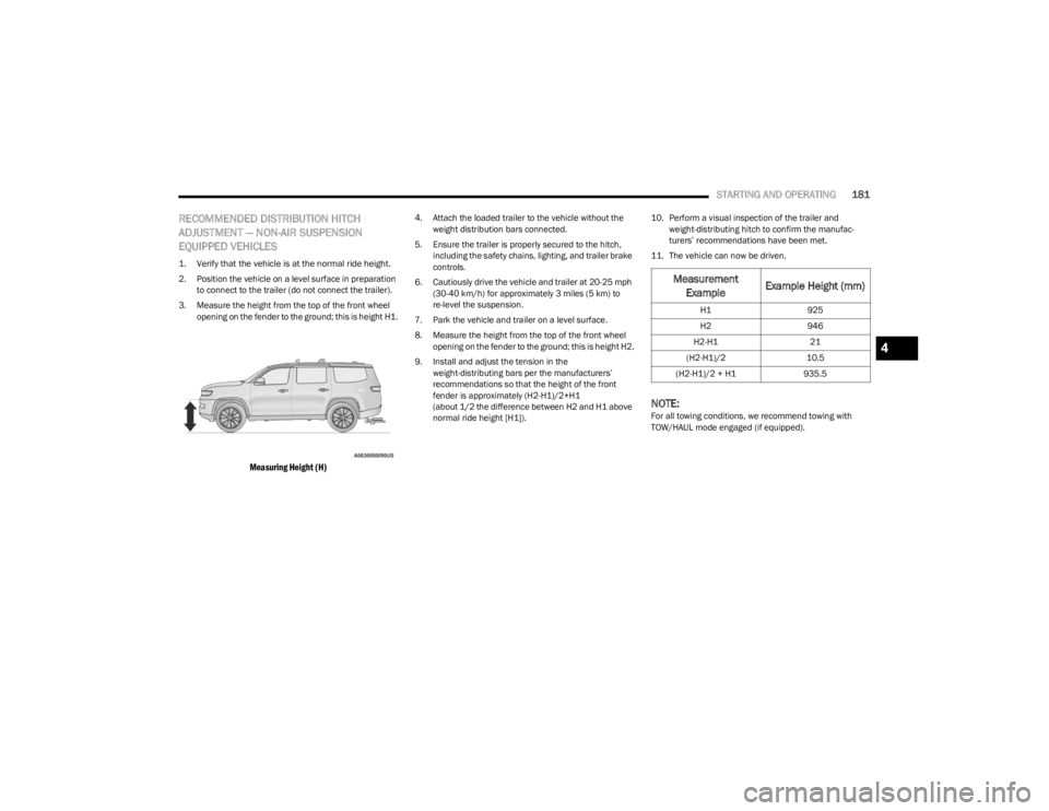
3. Measure the height from the top of the front wheel opening on the fender to the ground; this is height H1.
Measuring Height (H)
4. Attach the loaded trailer to the vehicle without the weight distribution bars connected.
5. Ensure the trailer is properly secured to the hitch, including the safety chains, lighting, and trailer brake
controls.
6. Cautiously drive the vehicle and trailer at 20-25 mph (30-40 km/h) for approximately 3 miles (5 km) to
re-level the suspension.
7. Park the vehicle and trailer on a level surface.
8. Measure the height from the top of the front wheel opening on the fender to the ground; this is height H2.
9. Install and adjust the tension in the weight-distributing bars per the manufacturers’
recommendations so that the height of the front
fender is approximately (H2-H1)/2+H1
(about 1/2 the difference between H2 and H1 above
normal ride height [H1]). 10. Perform a visual inspection of the trailer and
weight-distributing hitch to confirm the manufac -
turers’ recommendations have been met.
11. The vehicle can now be driven.
NOTE:For all towing conditions, we recommend towing with
TOW/HAUL mode engaged (if equipped).
Measurement Example Example Height (mm)
H1
925
H2 946
H2-H1 21
(H2-H1)/2 10.5
(H2-H1)/2 + H1 935.5
4
23_WS_OM_EN_USC_t.book Page 181
Page 195 of 396
STARTING AND OPERATING193
Shifting Out Of N (Neutral)
Use the following procedure to prepare your vehicle for
normal usage:
1. Bring the vehicle to a complete stop, leaving it
connected to the tow vehicle.
2. Apply the Electric Park Brake.
3. Start the engine.
NOTE:
Steps 1 through 5 are requirements that must be
met before pushing the N (Neutral) button, and
must continue to be met until the shift has been
completed. If any of these requirements are not
met before pushing the N (Neutral) button or are
no longer met during the shift, the N (Neutral) indi -
cator light will flash continuously until all require -
ments are met or until the N (Neutral) button is
released.
The ignition must be in the ON/RUN position for a
shift to take place and for the position indicator
lights to be operable. If the ignition is not in the
ON/RUN position, the shift will not take place and
no position indicator lights will be on or flashing.
A flashing N (Neutral) position indicator light indi-
cates that shift requirements have not been met.
4. Press and hold the brake pedal.
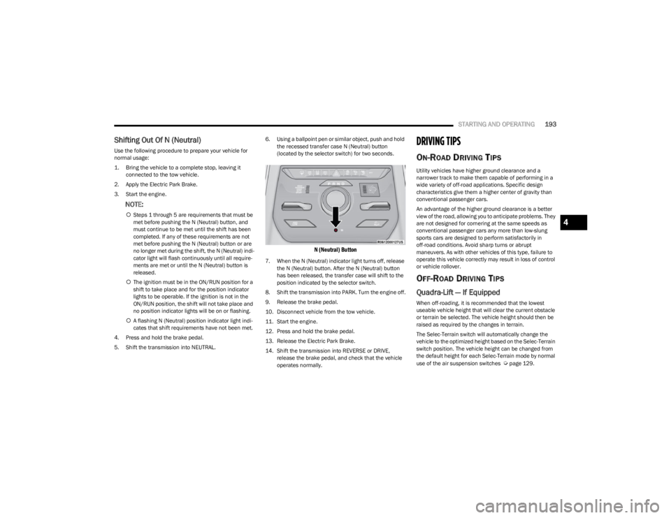
5. Shift the transmission into NEUTRAL. 6. Using a ballpoint pen or similar object, push and hold
the recessed transfer case N (Neutral) button
(located by the selector switch) for two seconds.
N (Neutral) Button
7. When the N (Neutral) indicator light turns off, release the N (Neutral) button. After the N (Neutral) button
has been released, the transfer case will shift to the
position indicated by the selector switch.
8. Shift the transmission into PARK. Turn the engine off.
9. Release the brake pedal.
10. Disconnect vehicle from the tow vehicle.
11. Start the engine.
12. Press and hold the brake pedal.
13. Release the Electric Park Brake.
14. Shift the transmission into REVERSE or DRIVE, release the brake pedal, and check that the vehicle
operates normally.
DRIVING TIPS
ON-ROAD DRIVING TIPS
Utility vehicles have higher ground clearance and a
narrower track to make them capable of performing in a
wide variety of off-road applications. Specific design
characteristics give them a higher center of gravity than
conventional passenger cars.
An advantage of the higher ground clearance is a better
view of the road, allowing you to anticipate problems. They
are not designed for cornering at the same speeds as
conventional passenger cars any more than low-slung
sports cars are designed to perform satisfactorily in
off-road conditions. Avoid sharp turns or abrupt
maneuvers. As with other vehicles of this type, failure to
operate this vehicle correctly may result in loss of control
or vehicle rollover.
OFF-ROAD DRIVING TIPS
Quadra-Lift — If Equipped
When off-roading, it is recommended that the lowest
useable vehicle height that will clear the current obstacle
or terrain be selected. The vehicle height should then be
raised as required by the changes in terrain.
The Selec-Terrain switch will automatically change the
vehicle to the optimized height based on the Selec-Terrain
switch position. The vehicle height can be changed from
the default height for each Selec-Terrain mode by normal
use of the air suspension switches
Úpage 129.
4
23_WS_OM_EN_USC_t.book Page 193
Page 196 of 396
194STARTING AND OPERATING
When To Use 4WD LOW — If Equipped
When off-road driving, shift to 4WD LOW for additional
traction. This range should be limited to extreme
situations such as deep snow, mud, or sand where
additional low speed pulling power is needed. Vehicle
speeds in excess of 25 mph (40 km/h) should be avoided
when in 4WD LOW.
Driving Through Water
Although your vehicle is capable of driving through water,
there are a number of precautions that must be
considered before entering the water.
NOTE:Your vehicle is capable of water fording in up to 20 inches
(51 cm) of water, while crossing small rivers or streams. To
maintain optimal performance of your vehicle's heating
and ventilation system it is recommended to switch the
system into recirculation mode during water fording. Driving through water more than a few inches/
centimeters deep will require extra caution to ensure
safety and prevent damage to your vehicle. If you must
drive through water, try to determine the depth and the
bottom condition (and location of any obstacles) prior to
entering. Proceed with caution and maintain a steady
controlled speed less than 5 mph (8 km/h) in deep water
to minimize wave effects.
Flowing Water
If the water is swift flowing and rising (as in storm run-off),
avoid crossing until the water level recedes and/or the
flow rate is reduced. If you must cross flowing water avoid
depths in excess of 9 inches (23 cm). The flowing water
can erode the streambed, causing your vehicle to sink into
deeper water. Determine exit point(s) that are
downstream of your entry point to allow for drifting.
Standing Water
Avoid driving in standing water deeper than 24 inches
(60 cm), and reduce speed appropriately to minimize
wave effects. Maximum speed is 5 mph (8 km/h).Maintenance
After driving through deep water, inspect your vehicle
fluids and lubricants (engine oil, transmission oil, axle,
transfer case) to ensure the fluids have not been
contaminated. Contaminated fluid (milky, foamy in
appearance) should be flushed/changed as soon as
possible to prevent component damage.
Driving In Snow, Mud And Sand
In heavy snow, when pulling a load, or for additional
control at slower speeds, shift the transmission to a low
gear and shift the transfer case to 4WD LOW if necessary
Úpage 129. Only shift into a lower gear to maintain
forward motion. Over-revving the engine can spin the
wheels and traction will be lost.
Avoid abrupt downshifts on icy or slippery roads, because
engine braking may cause skidding and loss of control.
Hill Climbing
NOTE:Before attempting to climb a hill, determine the conditions
at the crest and/or on the other side.
Before climbing a steep hill, shift the transmission to a
lower gear and shift the transfer case to 4WD LOW. Use
FIRST gear and 4WD LOW for very steep hills.
WARNING!
Do not drive in 4WD LOW on dry pavement; driveline
damage may result. 4WD LOW locks front and rear
drivelines together and does not allow for differential
action between the front to rear driveshafts. Driving in
4WD LOW on pavement will cause driveline binding;
use only on wet or slippery surfaces.
CAUTION!
When driving through water, do not exceed 5 mph
(8 km/h). Always check water depth before entering as
a precaution, and check all fluids afterward. Driving
through water may cause damage that may not be
covered by the New Vehicle Limited Warranty.
23_WS_OM_EN_USC_t.book Page 194
Page 223 of 396
MULTIMEDIA221
STEERING WHEEL AUDIO CONTROLS
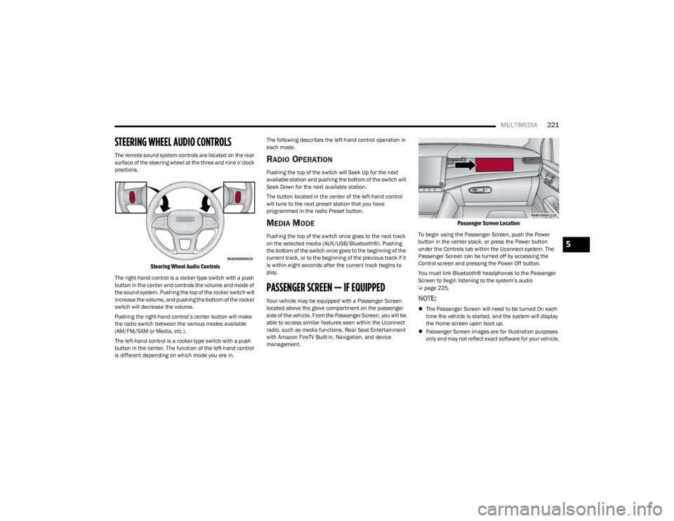
The remote sound system controls are located on the rear
surface of the steering wheel at the three and nine o’clock
positions.
Steering Wheel Audio Controls
The right-hand control is a rocker-type switch with a push
button in the center and controls the volume and mode of
the sound system. Pushing the top of the rocker switch will
increase the volume, and pushing the bottom of the rocker
switch will decrease the volume.
Pushing the right-hand control’s center button will make
the radio switch between the various modes available
(AM/FM/SXM or Media, etc.).
The left-hand control is a rocker-type switch with a push
button in the center. The function of the left-hand control
is different depending on which mode you are in. The following describes the left-hand control operation in
each mode.
RADIO OPERATION
Pushing the top of the switch will Seek Up for the next
available station and pushing the bottom of the switch will
Seek Down for the next available station.
The button located in the center of the left-hand control
will tune to the next preset station that you have
programmed in the radio Preset button.
MEDIA MODE
Pushing the top of the switch once goes to the next track
on the selected media (AUX/USB/Bluetooth®). Pushing
the bottom of the switch once goes to the beginning of the
current track, or to the beginning of the previous track if it
is within eight seconds after the current track begins to
play.
PASSENGER SCREEN — IF EQUIPPED
Your vehicle may be equipped with a Passenger Screen
located above the glove compartment on the passenger
side of the vehicle. From the Passenger Screen, you will be
able to access similar features seen within the Uconnect
radio, such as media functions, Rear Seat Entertainment
with Amazon FireTV Built-in, Navigation, and device
management.
Passenger Screen Location
To begin using the Passenger Screen, push the Power
button in the center stack, or press the Power button
under the Controls tab within the Uconnect system. The
Passenger Screen can be turned off by accessing the
Control screen and pressing the Power Off button.
You must link Bluetooth® headphones to the Passenger
Screen to begin listening to the system’s audio
Úpage 225.
NOTE:
The Passenger Screen will need to be turned On each
time the vehicle is started, and the system will display
the Home screen upon boot up.
Passenger Screen images are for illustration purposes
only and may not reflect exact software for your vehicle.
5
23_WS_OM_EN_USC_t.book Page 221
Page 229 of 396
MULTIMEDIA227
NOTE:To change the source within the app, press the source
name. Pressing this will open a menu with all available
sources. To change the audio source outside of the app,
press the media button, and then press the sources
button.
To exit the app, press any of the buttons on the bottom
menu bar. Day/Night Mode
Press the menu button in the upper left-hand corner to
access McIntosh settings. Tap on a mode to set it as the
default, or tap “Auto Mode” to enable your screen to
automatically switch between day and night modes.
Theater Mode
Press the menu button in the upper left-hand corner to
access McIntosh settings. Under Theater Mode, select
“On” to bring forward the McIntosh meters. This will
enlarge the meters for a more prominent view.
NOTE:Theater Mode will engage after 10 seconds without input
from the user.
For more information on McIntosh, the McIntosh app and
its functionality, please visit https://
www.mcintoshlabs.com.
Skip Backward
Press to skip backward. Press and hold to fast rewind.
Play/Pause Press to play/pause the track.
Skip Forward Press to skip forward. Press and hold to fast forward.
Repeat Press to repeat track. Press again to repeat playlist. Press again to turn off (works only
with a USB device).
Change Channel Down Press to change channel down. Press and hold to seek channel down. While using AM/
FM, pressing the channel down will change the frequency by 0.1. Pressing and holding in
AM/FM will seek channels.
Change Channel Up Press to change channel up. Press and hold to seek channel up. While using AM/FM,
pressing the channel up will change the frequency by 0.1. Pressing and holding in AM/FM
will seek channels.
Menu Press to access McIntosh settings.
About Press to learn more about McIntosh.
Audio Press to open the audio settings page of the Uconnect media player.
5
23_WS_OM_EN_USC_t.book Page 227
Page 238 of 396
236MULTIMEDIA
OFF-ROAD PAGES — IF EQUIPPED
Your vehicle may be equipped with Off-Road Pages, which
provides the vehicle status information while operating on
off-road conditions. It supplies information relating to the
vehicle ride height, the status of the transfer case, the
pitch and roll of the vehicle, and the active Selec-Terrain
Mode.
To access Off-Road Pages, press the Off Road button on
the touchscreen from the Vehicle menu, and then press
“Launch Off-Road”.
Off-Road Pages has the following selectable pages:
Vehicle Dynamics
Accessory Gauges
Pitch & Roll
Selec-Terrain — If Equipped
Suspension — If Equipped
NOTE:With a Connected Services subscription, you can record
your Off-Road data and send it directly to the mobile app.
Press the Record button to begin.
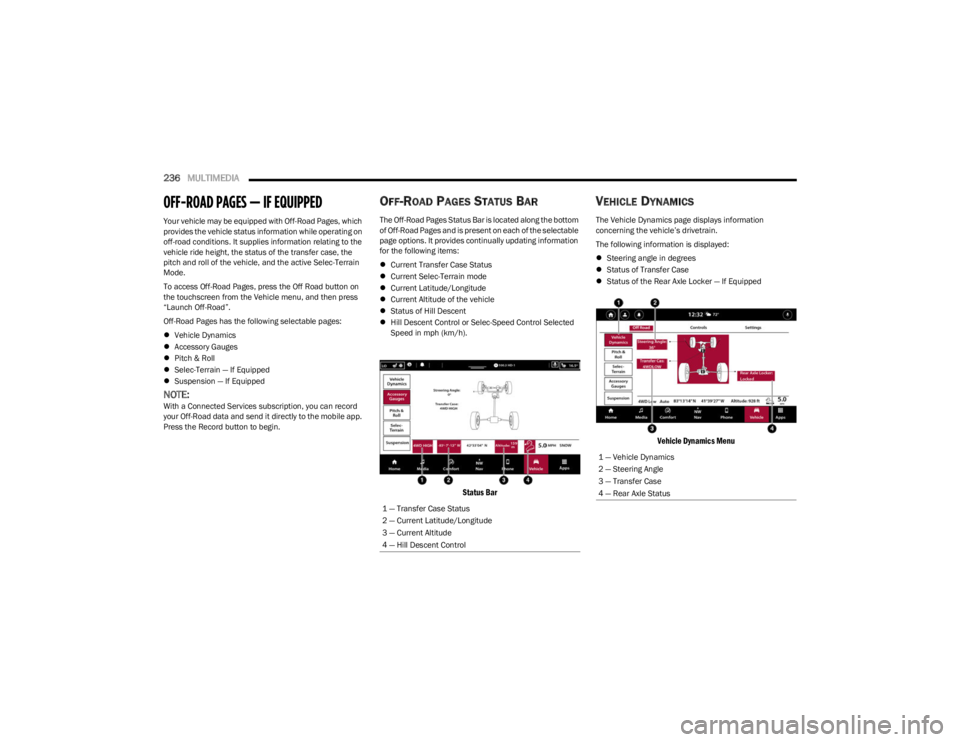
OFF-ROAD PAGES STATUS BAR
The Off-Road Pages Status Bar is located along the bottom
of Off-Road Pages and is present on each of the selectable
page options. It provides continually updating information
for the following items:
Current Transfer Case Status
Current Selec-Terrain mode
Current Latitude/Longitude
Current Altitude of the vehicle
Status of Hill Descent
Hill Descent Control or Selec-Speed Control Selected
Speed in mph (km/h).
Status Bar
VEHICLE DYNAMICS
The Vehicle Dynamics page displays information
concerning the vehicle’s drivetrain.
The following information is displayed:
Steering angle in degrees
Status of Transfer Case
Status of the Rear Axle Locker — If Equipped
Vehicle Dynamics Menu
1 — Transfer Case Status
2 — Current Latitude/Longitude
3 — Current Altitude
4 — Hill Descent Control
1 — Vehicle Dynamics
2 — Steering Angle
3 — Transfer Case
4 — Rear Axle Status
23_WS_OM_EN_USC_t.book Page 236
Page 241 of 396
239
(Continued)
SAFETY
SAFETY FEATURES
ANTI-LOCK BRAKE SYSTEM (ABS)
The ABS provides increased vehicle stability and brake
performance under most braking conditions. The system
automatically prevents wheel lock and enhances vehicle
control during braking.
The ABS performs a self-check cycle to ensure that the
ABS is working properly each time the vehicle is started
and driven. During this self-check, you may hear a slight
clicking sound as well as some related motor noises.
The ABS is activated during braking when the system
detects one or more wheels are beginning to lock. Road
conditions such as ice, snow, gravel, bumps, railroad
tracks, loose debris, or panic stops may increase the
likelihood of ABS activation(s).
You also may experience the following normal
characteristics when the ABS activates:
ABS motor noise or clicking sounds (you may continue
to hear for a short time after the stop).
Brake pedal pulsations.
A slight drop of the brake pedal at the end of the stop. The ABS is designed to function with the Original
Equipment Manufacturer (OEM) tires. Modification may
result in degraded ABS performance.
Anti-Lock Brake System (ABS) Warning
Light
The yellow ABS Warning Light will turn on when the ignition
is placed in the ON/RUN mode and may stay on for as long
as four seconds.
If the ABS Warning Light remains on or comes on while
driving, it indicates that the anti-lock portion of the brake
system is not functioning and that service is required.
However, the conventional brake system will continue to
operate normally if the ABS Warning Light is on.
If the ABS Warning Light is on, the brake system should be
serviced as soon as possible to restore the benefits of
Anti-Lock Brakes. If the ABS Warning Light does not come
on when the ignition is placed in the ON/RUN mode, have
the light repaired as soon as possible.
WARNING!
The ABS contains sophisticated electronic equip -
ment that may be susceptible to interference caused
by improperly installed or high output radio transmit -
ting equipment. This interference can cause possible
loss of anti-lock braking capability. Installation of
such equipment should be performed by qualified
professionals.
Pumping of the Anti-Lock Brakes will diminish their
effectiveness and may lead to a collision. Pumping
makes the stopping distance longer. Just press firmly
on your brake pedal when you need to slow down or
stop.
The ABS cannot prevent the natural laws of physics
from acting on the vehicle, nor can it increase
braking or steering efficiency beyond that afforded
by the condition of the vehicle brakes and tires or the
traction afforded.
The ABS cannot prevent collisions, including those
resulting from excessive speed in turns, following
another vehicle too closely, or hydroplaning.
The capabilities of an ABS equipped vehicle must
never be exploited in a reckless or dangerous
manner that could jeopardize the user’s safety or the
safety of others.
WARNING!
6
23_WS_OM_EN_USC_t.book Page 239