clock JEEP WRANGLER 2023 User Guide
[x] Cancel search | Manufacturer: JEEP, Model Year: 2023, Model line: WRANGLER, Model: JEEP WRANGLER 2023Pages: 396, PDF Size: 25.15 MB
Page 169 of 396
STARTING AND OPERATING167
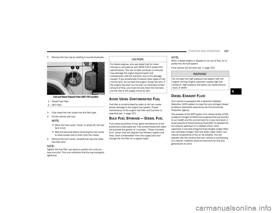
2. Remove the fuel cap by rotating it counterclockwise.
Fuel and Diesel Exhaust Fluid (DEF) Fill Location
3. Fully insert the fuel nozzle into the filler pipe.
4. Fill the vehicle with fuel.
NOTE:
When the fuel nozzle “clicks” or shuts off, the fuel
tank is full.
Wait five seconds before removing the fuel nozzle
to allow excess fuel to drain from the nozzle.
5. Remove the fuel nozzle, reinstall fuel cap and close fuel filler door.
NOTE:Tighten the fuel filler cap about a quarter turn until you
hear one click. This is an indication that the cap is properly
tightened.
AVOID USING CONTAMINATED FUEL
Fuel that is contaminated by water or dirt can cause
severe damage to the engine fuel system. Proper
maintenance of the engine fuel filter and fuel tank is
essential see
Úpage 321.
BULK FUEL STORAGE — DIESEL FUEL
If you store quantities of fuel, good maintenance of the
stored fuel is also essential. Fuel contaminated with water
will promote the growth of “microbes.” These microbes
form “slime” that will clog the fuel filtration system and
lines. Drain condensation from the supply tank and
change the line filter on a regular basis.
NOTE:When a diesel engine is allowed to run out of fuel, air is
pulled into the fuel system.
If the vehicle will not start see
Úpage 323.
DIESEL EXHAUST FLUID
Your vehicle is equipped with a Selective Catalytic
Reduction (SCR) system to meet the very stringent diesel
emissions standards required by the Environmental
Protection Agency.
The purpose of the SCR system is to reduce levels of NOx
(oxides of nitrogen emitted from engines) that are harmful
to our health and the environment to a near-zero level. A
small quantity of Diesel Exhaust Fluid (DEF) is injected into
the exhaust upstream of a catalyst where, when
vaporized, it converts smog-forming nitrogen oxides (NOx)
into harmless nitrogen (N2) and water vapor (H2O), two
natural components of the air we breathe. You can
operate with the comfort that your vehicle is contributing
to a cleaner, healthier world environment for this and
generations to come.
1 — Diesel Fuel Filler
2 — DEF Filler
CAUTION!
For diesel engines, only use diesel fuel for motor
vehicles in accordance with ASTM D-975 Grade S15
specifications. The use of other products or mixtures
may damage the engine beyond repair and
consequently void the warranty, due to the damage
caused. If you accidentally introduce other types of fuel
into the tank, do not start the engine. Empty the tank. If
the engine has been run for even an extremely limited
amount of time, you must not only drain the fuel tank,
but the rest of the supply circuit as well.
WARNING!
Do not open the high pressure fuel system with the
engine running. Engine operation causes high fuel
pressure. High pressure fuel spray can cause serious
injury or death.
4
23_JL_OM_EN_USC_t.book Page 167
Page 190 of 396
188MULTIMEDIA
Clock
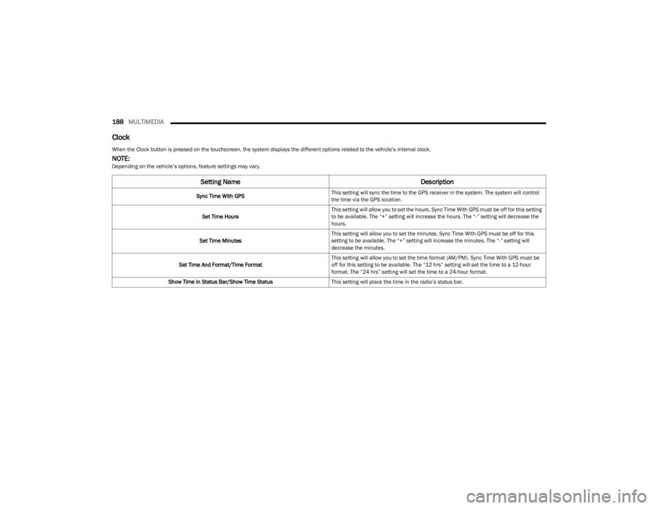
When the Clock button is pressed on the touchscreen, the system displays the different options related to the vehicle’s internal clock.
NOTE:Depending on the vehicle’s options, feature settings may vary.
Setting Name Description
Sync Time With GPSThis setting will sync the time to the GPS receiver in the system. The system will control
the time via the GPS location.
Set Time Hours This setting will allow you to set the hours. Sync Time With GPS must be off for this setting
to be available. The “+” setting will increase the hours. The “-” setting will decrease the
hours.
Set Time Minutes This setting will allow you to set the minutes. Sync Time With GPS must be off for this
setting to be available. The “+” setting will increase the minutes. The “-” setting will
decrease the minutes.
Set Time And Format/Time Format This setting will allow you to set the time format (AM/PM). Sync Time With GPS must be
off for this setting to be available. The “12 hrs” setting will set the time to a 12-hour
format. The “24 hrs” setting will set the time to a 24-hour format.
Show Time in Status Bar/Show Time Status This setting will place the time in the radio’s status bar.
23_JL_OM_EN_USC_t.book Page 188
Page 203 of 396
MULTIMEDIA201
UCONNECT MODES
STEERING WHEEL AUDIO CONTROLS
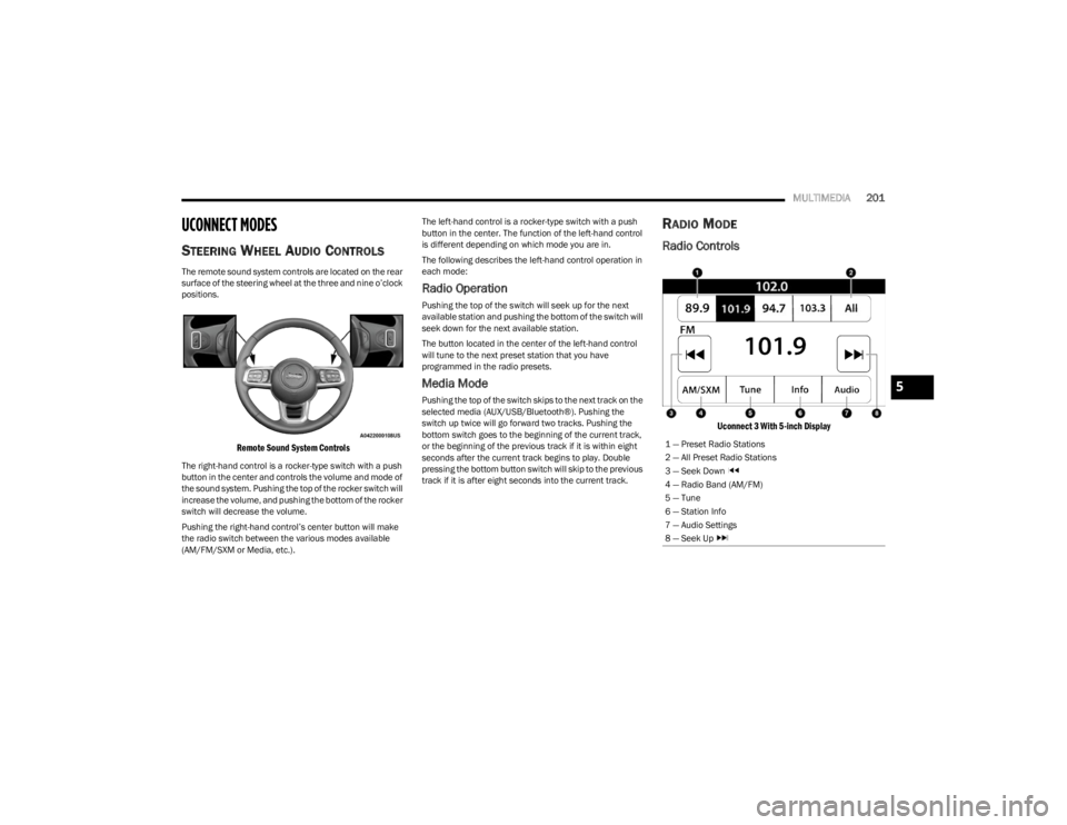
The remote sound system controls are located on the rear
surface of the steering wheel at the three and nine o’clock
positions.
Remote Sound System Controls
The right-hand control is a rocker-type switch with a push
button in the center and controls the volume and mode of
the sound system. Pushing the top of the rocker switch will
increase the volume, and pushing the bottom of the rocker
switch will decrease the volume.
Pushing the right-hand control’s center button will make
the radio switch between the various modes available
(AM/FM/SXM or Media, etc.). The left-hand control is a rocker-type switch with a push
button in the center. The function of the left-hand control
is different depending on which mode you are in.
The following describes the left-hand control operation in
each mode:
Radio Operation
Pushing the top of the switch will seek up for the next
available station and pushing the bottom of the switch will
seek down for the next available station.
The button located in the center of the left-hand control
will tune to the next preset station that you have
programmed in the radio presets.
Media Mode
Pushing the top of the switch skips to the next track on the
selected media (AUX/USB/Bluetooth®). Pushing the
switch up twice will go forward two tracks. Pushing the
bottom switch goes to the beginning of the current track,
or the beginning of the previous track if it is within eight
seconds after the current track begins to play. Double
pressing the bottom button switch will skip to the previous
track if it is after eight seconds into the current track.
RADIO MODE
Radio Controls
Uconnect 3 With 5-inch Display
1 — Preset Radio Stations
2 — All Preset Radio Stations
3 — Seek Down
4 — Radio Band (AM/FM)
5 — Tune
6 — Station Info
7 — Audio Settings
8 — Seek Up
5
23_JL_OM_EN_USC_t.book Page 201
Page 204 of 396
202MULTIMEDIA
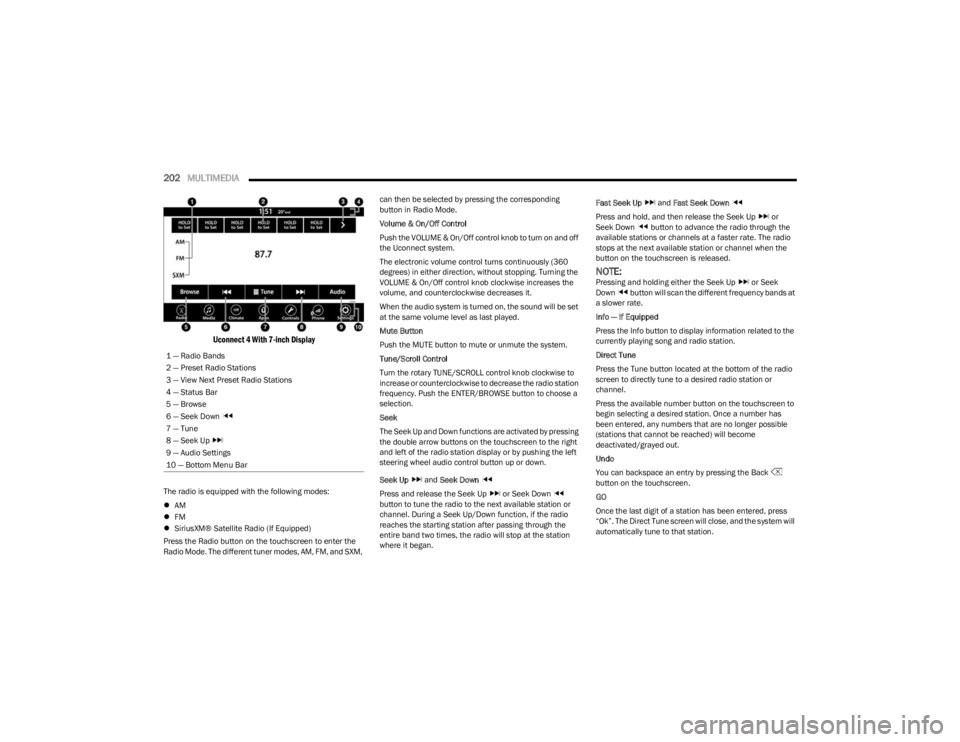
Uconnect 4 With 7-inch Display
The radio is equipped with the following modes:
AM
FM
SiriusXM® Satellite Radio (If Equipped)
Press the Radio button on the touchscreen to enter the
Radio Mode. The different tuner modes, AM, FM, and SXM, can then be selected by pressing the corresponding
button in Radio Mode.
Volume & On/Off Control
Push the VOLUME & On/Off control knob to turn on and off
the Uconnect system.
The electronic volume control turns continuously (360
degrees) in either direction, without stopping. Turning the
VOLUME & On/Off control knob clockwise increases the
volume, and counterclockwise decreases it.
When the audio system is turned on, the sound will be set
at the same volume level as last played.
Mute Button
Push the MUTE button to mute or unmute the system.
Tune/Scroll Control
Turn the rotary TUNE/SCROLL control knob clockwise to
increase or counterclockwise to decrease the radio station
frequency. Push the ENTER/BROWSE button to choose a
selection.
Seek
The Seek Up and Down functions are activated by pressing
the double arrow buttons on the touchscreen to the right
and left of the radio station display or by pushing the left
steering wheel audio control button up or down.
Seek Up
and Seek Down
Press and release the Seek Up or Seek Down
button to tune the radio to the next available station or
channel. During a Seek Up/Down function, if the radio
reaches the starting station after passing through the
entire band two times, the radio will stop at the station
where it began. Fast Seek Up
and Fast Seek Down
Press and hold, and then release the Seek Up or
Seek Down button to advance the radio through the
available stations or channels at a faster rate. The radio
stops at the next available station or channel when the
button on the touchscreen is released.
NOTE:Pressing and holding either the Seek Up or Seek
Down button will scan the different frequency bands at
a slower rate.
Info — If Equipped
Press the Info button to display information related to the
currently playing song and radio station.
Direct Tune
Press the Tune button located at the bottom of the radio
screen to directly tune to a desired radio station or
channel.
Press the available number button on the touchscreen to
begin selecting a desired station. Once a number has
been entered, any numbers that are no longer possible
(stations that cannot be reached) will become
deactivated/grayed out.
Undo
You can backspace an entry by pressing the Back
button on the touchscreen.
GO
Once the last digit of a station has been entered, press
“Ok”. The Direct Tune screen will close, and the system will
automatically tune to that station.
1 — Radio Bands
2 — Preset Radio Stations
3 — View Next Preset Radio Stations
4 — Status Bar
5 — Browse
6 — Seek Down
7 — Tune
8 — Seek Up
9 — Audio Settings
10 — Bottom Menu Bar
23_JL_OM_EN_USC_t.book Page 202
Page 297 of 396
IN CASE OF EMERGENCY295
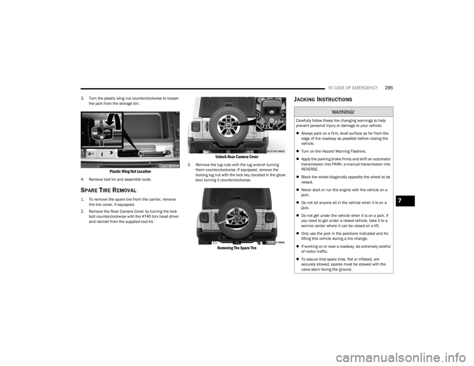
3. Turn the plastic wing nut counterclockwise to loosen
the jack from the storage bin.
Plastic Wing Nut Location
4. Remove tool kit and assemble tools.
SPARE TIRE REMOVAL
1. To remove the spare tire from the carrier, remove the tire cover, if equipped.
2. Remove the Rear Camera Cover by turning the lock bolt counterclockwise with the #T40 torx head driver
and ratchet from the supplied tool kit.
Unlock Rear Camera Cover
3. Remove the lug nuts with the lug wrench turning them counterclockwise. If equipped, remove the
locking lug nut with the lock key (located in the glove
box) turning it counterclockwise.
Removing The Spare Tire
JACKING INSTRUCTIONS
WARNING!
Carefully follow these tire changing warnings to help
prevent personal injury or damage to your vehicle:
Always park on a firm, level surface as far from the
edge of the roadway as possible before raising the
vehicle.
Turn on the Hazard Warning Flashers.
Apply the parking brake firmly and shift an automatic
transmission into PARK; a manual transmission into
REVERSE.
Block the wheel diagonally opposite the wheel to be
raised.
Never start or run the engine with the vehicle on a
jack.
Do not let anyone sit in the vehicle when it is on a
jack.
Do not get under the vehicle when it is on a jack. If
you need to get under a raised vehicle, take it to a
service center where it can be raised on a lift.
Only use the jack in the positions indicated and for
lifting this vehicle during a tire change.
If working on or near a roadway, be extremely careful
of motor traffic.
To assure that spare tires, flat or inflated, are
securely stowed, spares must be stowed with the
valve stem facing the ground.
7
23_JL_OM_EN_USC_t.book Page 295
Page 299 of 396
IN CASE OF EMERGENCY297
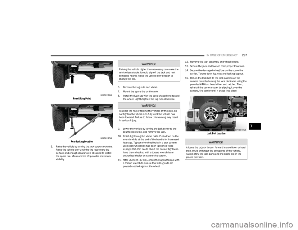
Rear Lifting Point
Rear Jacking Location
5. Raise the vehicle by turning the jack screw clockwise. Raise the vehicle only until the tire just clears the
surface and enough clearance is obtained to install
the spare tire. Minimum tire lift provides maximum
stability. 6. Remove the lug nuts and wheel.
7. Mount the spare tire on the axle.
8. Install the lug nuts with the cone-shaped end toward
the wheel. Lightly tighten the lug nuts clockwise.
9. Lower the vehicle by turning the jack screw to the counterclockwise, and remove the jack.
10. Finish tightening the wheel bolts. Push down on the wrench while at the end of the handle for increased
leverage. Tighten the wheel bolts in a star pattern
until each wheel bolt has been tightened twice Úpage 368. If in doubt about the correct tightness,
have them checked with a torque wrench by an
authorized dealer or at a service station.
11. After 25 miles (40 km), check the lug nut torque with a torque wrench to ensure that all lug nuts are
properly seated against the wheel. 12. Remove the jack assembly and wheel blocks.
13. Secure the jack and tools in their proper locations.
14. Secure the damaged wheel/tire on the spare tire
carrier. Torque down lug nuts and locking lug nut.
15. Return the lock bolt to the lock position on the camera cover by turning the lock clockwise using the
provided #40 torx head driver and ratchet. Then,
reinstall the camera cover by slipping it over the
camera/tire carrier until it snaps into place.
Lock Bolt Location
WARNING!
Raising the vehicle higher than necessary can make the
vehicle less stable. It could slip off the jack and hurt
someone near it. Raise the vehicle only enough to
change the tire.
WARNING!
To avoid the risk of forcing the vehicle off the jack, do
not tighten the wheel nuts fully until the vehicle has
been lowered. Failure to follow this warning may result
in serious injury.
WARNING!
A loose tire or jack thrown forward in a collision or hard
stop, could endanger the occupants of the vehicle.
Always stow the jack parts and the spare tire in the
places provided.
7
23_JL_OM_EN_USC_t.book Page 297
Page 323 of 396
SERVICING AND MAINTENANCE321
DRAINING FUEL/WATER SEPARATOR
F
ILTER — DIESEL ENGINE
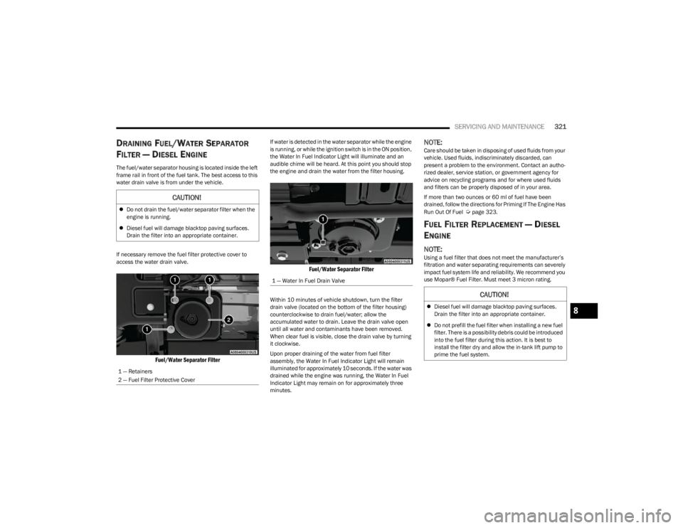
The fuel/water separator housing is located inside the left
frame rail in front of the fuel tank. The best access to this
water drain valve is from under the vehicle.
If necessary remove the fuel filter protective cover to
access the water drain valve.
Fuel/Water Separator Filter
If water is detected in the water separator while the engine
is running, or while the ignition switch is in the ON position,
the Water In Fuel Indicator Light will illuminate and an
audible chime will be heard. At this point you should stop
the engine and drain the water from the filter housing.
Fuel/Water Separator Filter
Within 10 minutes of vehicle shutdown, turn the filter
drain valve (located on the bottom of the filter housing)
counterclockwise to drain fuel/water; allow the
accumulated water to drain. Leave the drain valve open
until all water and contaminants have been removed.
When clear fuel is visible, close the drain valve by turning
it clockwise.
Upon proper draining of the water from fuel filter
assembly, the Water In Fuel Indicator Light will remain
illuminated for approximately 10 seconds. If the water was
drained while the engine was running, the Water In Fuel
Indicator Light may remain on for approximately three
minutes.
NOTE:Care should be taken in disposing of used fluids from your
vehicle. Used fluids, indiscriminately discarded, can
present a problem to the environment. Contact an autho-
rized dealer, service station, or government agency for
advice on recycling programs and for where used fluids
and filters can be properly disposed of in your area.
If more than two ounces or 60 ml of fuel have been
drained, follow the directions for Priming If The Engine Has
Run Out Of Fuel
Úpage 323.
FUEL FILTER REPLACEMENT — DIESEL
E
NGINE
NOTE:Using a fuel filter that does not meet the manufacturer’s
filtration and water separating requirements can severely
impact fuel system life and reliability. We recommend you
use Mopar® Fuel Filter. Must meet 3 micron rating.
CAUTION!
Do not drain the fuel/water separator filter when the
engine is running.
Diesel fuel will damage blacktop paving surfaces.
Drain the filter into an appropriate container.
1 — Retainers
2 — Fuel Filter Protective Cover
1 — Water In Fuel Drain Valve
CAUTION!
Diesel fuel will damage blacktop paving surfaces.
Drain the filter into an appropriate container.
Do not prefill the fuel filter when installing a new fuel
filter. There is a possibility debris could be introduced
into the fuel filter during this action. It is best to
install the filter dry and allow the in-tank lift pump to
prime the fuel system.8
23_JL_OM_EN_USC_t.book Page 321
Page 324 of 396
322SERVICING AND MAINTENANCE
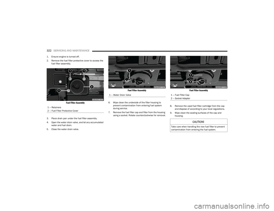
1. Ensure engine is turned off.
2. Remove the fuel filter protective cover to access the
fuel filter assembly.
Fuel Filter Assembly
3. Place drain pan under the fuel filter assembly.
4. Open the water drain valve, and let any accumulated water and fuel drain.
5. Close the water drain valve.
Fuel Filter Assembly
6. Wipe clean the underside of the filter housing to prevent contamination from entering fuel system
during service.
7. Remove the fuel filter cap and filter from the housing using a socket. Rotate counterclockwise for removal.
Fuel Filter Assembly
8. Remove the used fuel filter cartridge from the cap and dispose of according to your local regulations.
9. Wipe clean the sealing surfaces of the cap and housing.
1 — Retainers
2 — Fuel Filter Protective Cover
1 — Water Drain Valve1 — Fuel Filter Cap
2 — Socket Adapter
CAUTION!
Take care when handling the new fuel filter to prevent
contamination from entering the fuel system.
23_JL_OM_EN_USC_t.book Page 322
Page 325 of 396

SERVICING AND MAINTENANCE323
10. Lubricate o-ring on the cap with clean engine oil.
11. Install the new fuel filter cartridge onto the cap.
12. Insert the cap and filter into the housing with
clockwise rotation, use a socket to tighten.
13. Push the ignition switch twice without your foot on the brake to place vehicle in RUN position. This will
activate the in tank fuel pump for approximately 30
seconds. Repeat this process twice to prime the fuel
system. Start the engine using the Normal Starting
procedure. After engine start, verify the fuel filter cap
does not leak.
PRIMING IF THE ENGINE HAS RUN OUT
O
F FUEL — DIESEL ENGINE
1. Add a substantial amount of fuel to the tank, approx -
imately 2 to 5 gal (8L to 19L).
2. Push ignition switch twice without your foot on brake to put vehicle in RUN position. This will activate the in
tank fuel pump for approximately 30 seconds.
Repeat this process twice to prime the fuel system.
3. Start the engine using the Normal Starting procedure
Úpage 130.
NOTE:The engine may run rough until the air is forced from all
the fuel lines.
NOTE:
Use of biodiesel mixture in excess of 20% can nega -
tively impact the fuel filter's ability to separate water
from the fuel, resulting in high pressure fuel system
corrosion or damage.
In addition, commercially available fuel additives are
not necessary for the proper operation of your diesel
engine.
For extreme cold conditions, "Mopar® Premium Diesel
Fuel Treatment" is recommended to assist with cold
starting.
INTERVENTION REGENERATION
S
TRATEGY — MESSAGE PROCESS FLOW
This engine meets all required diesel engine emissions
standards. To achieve these emissions standards, your
vehicle is equipped with a state-of-the-art engine and
exhaust system. These systems are seamlessly integrated
into your vehicle and managed by the Powertrain Control
Module (PCM). The PCM manages engine combustion to
allow the exhaust system’s catalyst to trap and burn
Particulate Matter (PM) pollutants, with no input or
interaction on your part.
Additionally, your vehicle has the ability to alert you to
additional maintenance required on your vehicle or
engine.
Refer to Instrument Cluster Display for further information
Úpage 108.
DIESEL EXHAUST FLUID
Diesel Exhaust Fluid (DEF) sometimes known simply by
the name of its active component, UREA—is a key
component of Selective Catalytic Reduction (SCR)
systems, which help diesel vehicles meet stringent
emission regulations. DEF is a liquid reducing agent that
WARNING!
Do not open the high pressure fuel system with the
engine running. Engine operation causes high fuel
pressure. High pressure fuel spray can cause serious
injury or death.
CAUTION!
The starter motor will engage for approximately
30 seconds at a time. Allow two minutes between
cranking intervals.
WARNING!
Do not use alcohol or gasoline as a fuel blending agent.
They can be unstable under certain conditions and be
hazardous or explosive when mixed with diesel fuel.
CAUTION!
Due to lack of lubricants in alcohol or gasoline, the use
of these fuels can cause damage to the fuel system.WARNING!
A hot exhaust system can start a fire if you park over
materials that can burn. Such materials might be grass
or leaves coming into contact with your exhaust system.
Do not park or operate your vehicle in areas where your
exhaust system can contact anything that can burn.
8
23_JL_OM_EN_USC_t.book Page 323
Page 345 of 396
SERVICING AND MAINTENANCE343
Bulb Replacement
NOTE:Lens fogging can occur under certain atmospheric condi -
tions. This will usually clear as atmospheric conditions
change to allow the condensation to change back into a
vapor. Turning the lamps on will usually accelerate the
clearing process.
HALOGEN HEADLAMPS
See the following steps to replace:
1. Open hood and support using prop rod.
2. Remove the front grille. Turn the retainers along the top a quarter turn counterclockwise and remove. 3. Pull the bottom of the grille away starting at one side
and working toward the other.
4. Remove the three screws holding the headlamp to the vehicle.
5. Remove lamp from the vehicle.
6. Remove the lamp from the collar.
7. Grab the bulb and rotate a quarter turn counter -
clockwise.
8. Pull the bulb from the housing.
9. Push connector locking tab to the unlock position.
10. Remove connector from bulb.
11. Push connector onto new bulb base, and push the connector locking tab to the lock position. 12. Reinstall bulb housing. Rotate the bulb a quarter turn
clockwise.
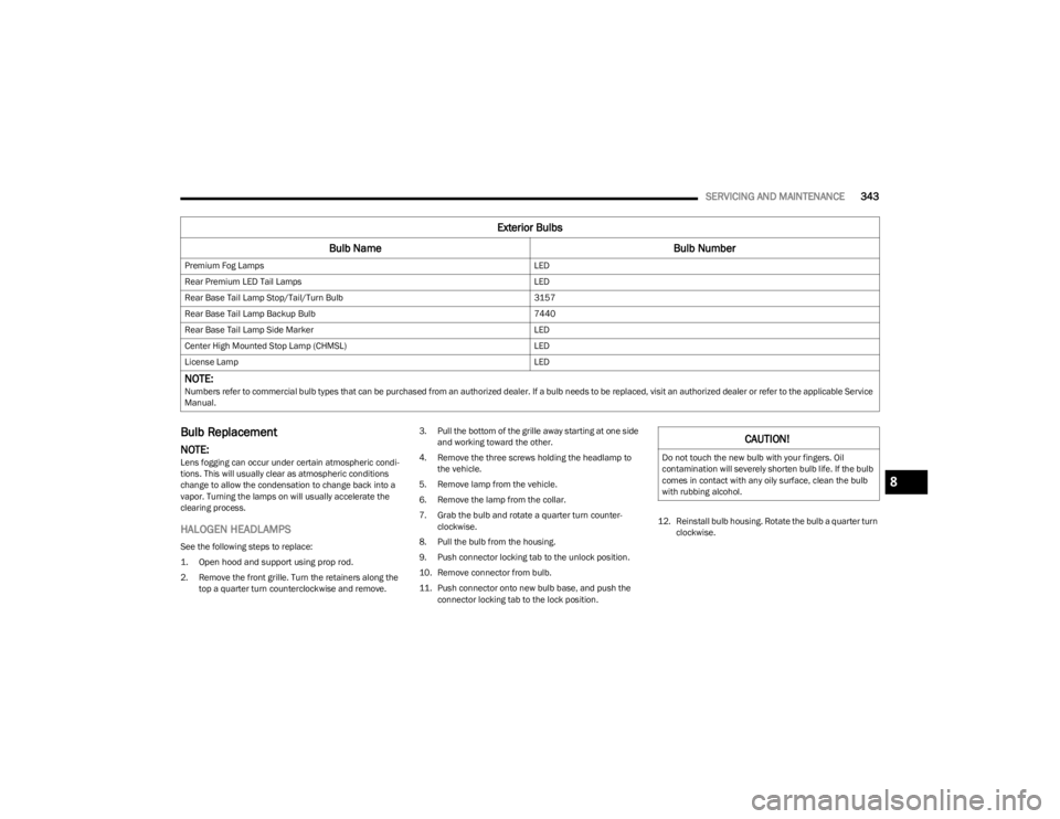
Premium Fog Lamps
LED
Rear Premium LED Tail Lamps LED
Rear Base Tail Lamp Stop/Tail/Turn Bulb 3157
Rear Base Tail Lamp Backup Bulb 7440
Rear Base Tail Lamp Side Marker LED
Center High Mounted Stop Lamp (CHMSL) LED
License Lamp LED
NOTE: Numbers refer to commercial bulb types that can be purchased from an authorized dealer. If a bulb needs to be replaced, visit an authorized dealer or refer to the applicable Service
Manual.
Exterior Bulbs
Bulb Name Bulb Number
CAUTION!
Do not touch the new bulb with your fingers. Oil
contamination will severely shorten bulb life. If the bulb
comes in contact with any oily surface, clean the bulb
with rubbing alcohol.
8
23_JL_OM_EN_USC_t.book Page 343