stop start JEEP WRANGLER 2023 User Guide
[x] Cancel search | Manufacturer: JEEP, Model Year: 2023, Model line: WRANGLER, Model: JEEP WRANGLER 2023Pages: 396, PDF Size: 25.15 MB
Page 61 of 396
GETTING TO KNOW YOUR VEHICLE59
AUTOMATIC TEMPERATURE CONTROL
(ATC) — I
F EQUIPPED
Automatic Operation
1. Push the AUTO button on the faceplate, or the AUTO
button on the touchscreen on the Automatic
Temperature Control (ATC) Panel.
2. Next, adjust the temperature that you would like the system to maintain by adjusting the driver and
passenger temperature control buttons. Once the
desired temperature is displayed, the system will
achieve and automatically maintain that comfort
level.
3. When the system is set up for your comfort level, it is not necessary to change the settings. You will
experience the greatest efficiency by simply allowing
the system to function automatically.
NOTE:
It is not necessary to move the temperature settings for
cold or hot vehicles. The system automatically adjusts
the temperature, mode, and blower speed to provide
comfort as quickly as possible.
The temperature can be displayed in US or Metric units
by selecting the US/Metric customer-programmable
feature within Uconnect Settings
Úpage 184.
To provide you with maximum comfort in the Automatic
mode during cold start-ups, the blower fan will remain on
low until the engine warms up. The blower will increase in
speed and transition into Auto mode.
Manual Operation Override
This system offers a full complement of manual override
features. The AUTO symbol in the front ATC display will be
turned off when the system is being used in the manual
mode.
CLIMATE VOICE COMMANDS
Adjust vehicle temperatures hands-free and keep
everyone comfortable while you keep moving ahead.
Push the VR button on the steering wheel. After the beep,
say one of the following commands:
“Set the driver temperature to 70 degrees ”
“Set the passenger temperature to 70 degrees ”
Did You Know: Voice Command for Climate may only be
used to adjust the interior temperature of your vehicle.
Voice Command will not work to adjust the heated seats
or steering wheel if equipped.
OPERATING TIPS
Refer to the chart at the end of this section for suggested
control settings for various weather conditions.
Summer Operation
The engine cooling system must be protected with a
high-quality antifreeze coolant to provide proper corrosion
protection and to protect against engine overheating. OAT
coolant (conforming to MS.90032) is recommended.
Winter Operation
To ensure the best possible heater and defroster
performance, make sure the engine cooling system is
functioning properly and the proper amount, type, and concentration of coolant is used. Use of the Air
Recirculation mode during Winter months is not
recommended, because it may cause window fogging.
Vacation/Storage
For information on maintaining the Climate Control system
when the vehicle is being stored for an extended period of
time, see
Úpage 359.
Window Fogging
Vehicle windows tend to fog on the inside in mild, rainy,
and/or humid weather. To clear the windows, select
Defrost or Mix mode and increase the front blower speed.
Do not use the Recirculation mode without A/C for long
periods, as fogging may occur.
Outside Air Intake
Make sure the air intake, located directly in front of the
windshield, is free of obstructions, such as leaves. Leaves
collected in the air intake may reduce airflow, and if they
enter the plenum, they could plug the water drains. In
Winter months, make sure the air intake is clear of ice,
slush, and snow.
Cabin Air Filter
The Climate Control system filters out dust and pollen
from the air. Contact an authorized dealer to service your
cabin air filter, and to have it replaced when needed.
Stop/Start System — If Equipped
While in an Autostop, the Climate Control system may
automatically adjust airflow to maintain cabin comfort.
Customer settings will be maintained upon return to an
engine running condition.
2
23_JL_OM_EN_USC_t.book Page 59
Page 95 of 396
GETTING TO KNOW YOUR VEHICLE93
Ignition Off Operation
The power top switch can remain active in Accessory Delay
for up to approximately 10 minutes after the vehicle’s
ignition is placed to the OFF position. Opening either front
door will cancel this feature.
NOTE:Ignition Off time is programmable through the Uconnect
system Úpage 184.
Relearn Procedure
For vehicles equipped with a power top, there is a relearn
procedure that allows you to calibrate the power top when
the “Express Mode” stops working. To reset the power top,
follow these steps:
1. Place the ignition in the RUN position, and start the
vehicle.
NOTE:The engine must be running to perform the relearn
procedure.
2. Ensure the power top is in the fully closed position.
3. Push and hold the Close switch for 10 seconds. This will put the power top into calibration mode.
4. Continue holding down the close button while the top goes fully open and then back to fully close.
5. Once the power top has stopped in the fully closed position, release the close button. The power top is
now reset and ready to use.
NOTE:If the close button is released anytime during the
relearning process, the relearn may not be complete, and
the procedure must be repeated.
Rear Quarter Window Removal
On vehicles equipped with a Power Sliding Top, the rear
quarter windows can be removed. To remove these
windows, follow this procedure:
1. Open the swing gate, and lift the rear window.
2. Open both side doors nearest the quarter windows.
3. Locate the rear quarter window latches (two on each window) on the interior of the windows.
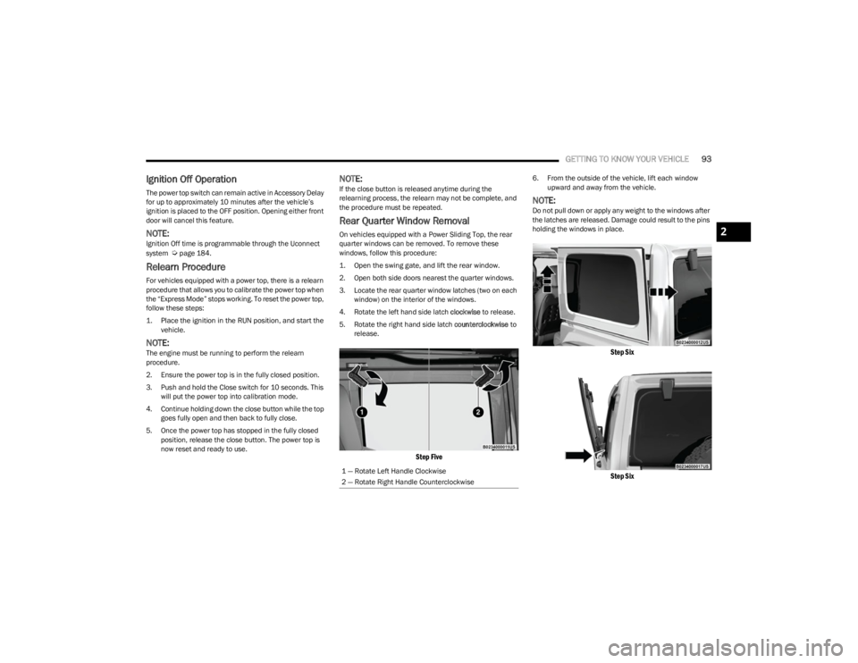
4. Rotate the left hand side latch clockwise to release.
5. Rotate the right hand side latch counterclockwise to
release.
Step Five
6. From the outside of the vehicle, lift each window upward and away from the vehicle.
NOTE:Do not pull down or apply any weight to the windows after
the latches are released. Damage could result to the pins
holding the windows in place.
Step Six
Step Six
1 — Rotate Left Handle Clockwise
2 — Rotate Right Handle Counterclockwise
2
23_JL_OM_EN_USC_t.book Page 93
Page 114 of 396
112GETTING TO KNOW YOUR INSTRUMENT PANEL
INSTRUMENT CLUSTER DISPLAY
S
ELECTABLE ITEMS
The instrument cluster display can be used to view the
following main menu items:
NOTE:Depending on the vehicles options, feature settings may
vary.
Speedometer
Push and release the up or down arrow button
until the speedometer menu icon is displayed in the
instrument cluster display. Push and release the OK
button to toggle between MPH and km/h.
Vehicle Info
Push and release the up or down arrow button
until the Vehicle Info menu icon is displayed in the
instrument cluster display. Push and release the left or
right arrow button to scroll through the information
submenus and push and release the OK button to select
or reset the resettable submenus.
Off Road
Push and release the up or down arrow button
until the Off Road menu icon is displayed in the instrument
cluster display. Push and release the left or right
arrow button to scroll through the information submenus.
Drivetrain
Front Wheel Angle: displays the graphical and
numerical value of calculated average front wheel
angle from the steering wheel orientation.
Transfer Case Lock Status: displays “Lock”
graphic only during 4WD High, 4WD High Part
Time, 4WD Low status.
Axle Lock And Sway Bar Status (If Equipped):
displays front and rear or rear only axle locker
graphic, and sway bar connection graphic with text
message (connected or disconnected).
Pitch And Roll
Displays the pitch and roll of the vehicle in the
graphic with the angle number on the screen.
NOTE:When vehicle speed becomes too high to display the pitch
and roll, “- -” will display in place of the numbers, and the
graphic will be greyed out. A message indicating the
necessary speed for the feature to become available will
also display.
Driver Assist — If Equipped
The Driver Assist menu displays the status of the ACC
systems.
Push and release the up or down arrow button
until the Driver Assist menu is displayed in the instrument
cluster display.
Adaptive Cruise Control (ACC) Feature — If Equipped
The instrument cluster display displays the current ACC
system settings. The information displayed depends on
ACC system status.
Push the ACC ON/OFF button (located on the steering
wheel) until one of the following displays in the instrument
cluster display:
Adaptive Cruise Control Off
When ACC is deactivated, the display will read “Adaptive
Cruise Control Off.”
Adaptive Cruise Control Ready
When ACC is activated but the vehicle speed setting has
not been selected, the display will read “Adaptive Cruise
Control Ready.”
Speedometer
Driver Assist — If
EquippedStop/Start
Vehicle Info Fuel Economy Audio
Off Road Trip Info Messages
Screen Setup Phone Call
Status — If
Equipped
Tire PressureSingle Gauge
Submenu — If
EquippedCritical Level
Logic — If
Equipped
Oil Life Diesel Exhaust
Fluid Level — If
EquippedCoolant
Temperature
Oil Pressure Oil Temperature Transmission
Temperature —
Automatic
Transmission
Only
Battery Voltage
23_JL_OM_EN_USC_t.book Page 112
Page 115 of 396
GETTING TO KNOW YOUR INSTRUMENT PANEL113
Push the SET + or the SET - button (located on the steering
wheel), and the following will display in the instrument
cluster display.
ACC SET
When ACC is set, the set speed will display in the
instrument cluster.
The ACC screen may display once again if any of the
following ACC activity occurs:
System Cancel
Driver Override
System Off
ACC Proximity Warning
ACC Unavailable Warning
NOTE:
The instrument cluster display will return to the last
display selected after five seconds of no ACC display
activity
Úpage 152.
Fuel Economy
Push and release the up or down arrow button
until the Fuel Economy icon is highlighted in the
instrument cluster display. Push and hold the OK button to
reset average fuel economy feature.
Toggle left or right to select a display with or
without Current Fuel Economy Information.
Range – The display shows the estimated distance (mi
or km) that can be traveled with the fuel remaining in
the tank. When the Range value is less than 10 miles
(16 kilometers), the Range display will change to a
“LOW” message. Adding a significant amount of fuel to
the vehicle will turn off the “LOW” message and a new Range value will display. Range cannot be reset
through the
OK button.
NOTE:Significant changes in driving style or vehicle loading will
greatly affect the actual drivable distance of the vehicle,
regardless of the Range displayed value.
Average – The display shows the average fuel economy
(MPG, L/100 km, or km/L) since the last reset.
Current – This display shows the current fuel economy
(MPG, L/100 km, km/L) while driving.
Trip Info
Push and release the up or down arrow button
until the Trip icon/title is highlighted in the instrument
cluster display, then push and release the left or
right arrow button to select Trip A or Trip B.
The Trip A and Trip B information will display the following:
Distance
Average Fuel Economy
Elapsed Time
Hold the OK button to reset all the information.
Stop/Start — If Equipped
Push and release the up or down arrow button
until the Stop/Start icon/title is highlighted in the
instrument cluster display. The screen will display the
Stop/Start status.
Audio
Push and release the up or down arrow button
until the Audio Menu icon/title is highlighted in the
instrument cluster display. This menu will display the
audio source information, including the Song name, Artist
name, and audio source with an accompanying graphic.
Messages
Push and release the up or down arrow button
until the Messages Menu item is highlighted. This feature
shows the number of stored warning messages. Pushing
the right arrow button will allow you to see what the
stored messages are.
When no messages are present, a “No Stored Messages”
will display.
Screen Setup
Push and release the up or down arrow button
until the Screen Setup Menu Icon/Title is highlighted in
the instrument cluster display. Push and release the OK
button to enter the submenus and follow the prompts on
the screen as needed. The Screen Setup feature allows
you to change what information is displayed in the
instrument cluster as well as the location that information
is displayed.
NOTE:Based upon equipment options and current vehicle
status, some of the features may not be available.
3
23_JL_OM_EN_USC_t.book Page 113
Page 116 of 396
114GETTING TO KNOW YOUR INSTRUMENT PANEL
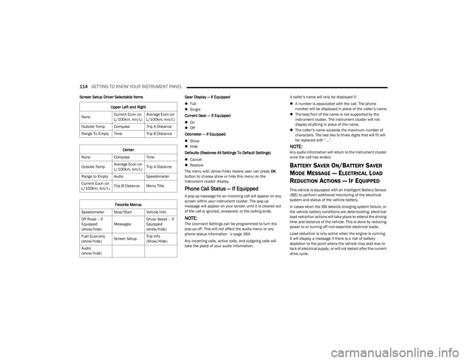
Screen Setup Driver Selectable Items Gear Display — If Equipped
Full
Single
Current Gear — If Equipped
On
Off
Odometer — If Equipped
Show
Hide
Defaults (Restores All Settings To Default Settings)
Cancel
Restore
The menu with (show/hide) means user can press OK
button to choose show or hide this menu on the
instrument cluster display.
Phone Call Status — If Equipped
A pop-up message for an incoming call will appear on any
screen within your instrument cluster. The pop-up
message will appear on your screen until it is cleared out
of the call is ignored, answered, or the calling ends.
NOTE:The Uconnect Settings can be programmed to turn the
pop-up off. This will not affect the audio menu or any
phone status information
Úpage 184.
Any incoming calls, active calls, and outgoing calls will
take the place of your audio information. A caller’s name will only be displayed if:
A number is associated with the call. The phone
number will be displayed in place of the caller’s name.
The test/font of the name is not supported by the
instrument cluster. The instrument cluster will not
display anything in place of the name.
The caller’s name exceeds the maximum number of
characters. The last two to three digits that will fit will
be replaced with “...”.
NOTE:Any audio information will return to the instrument cluster
once the call has ended.
BATTERY SAVER ON/BATTERY SAVER
M
ODE MESSAGE — ELECTRICAL LOAD
R
EDUCTION ACTIONS — IF EQUIPPED
This vehicle is equipped with an Intelligent Battery Sensor
(IBS) to perform additional monitoring of the electrical
system and status of the vehicle battery.
In cases when the IBS detects charging system failure, or
the vehicle battery conditions are deteriorating, electrical
load reduction actions will take place to extend the driving
time and distance of the vehicle. This is done by reducing
power to or turning off non-essential electrical loads.
Load reduction is only active when the engine is running.
It will display a message if there is a risk of battery
depletion to the point where the vehicle may stall due to
lack of electrical supply, or will not restart after the current
drive cycle.
Upper Left and Right
None Current Econ (or
L/100km, km/L)Average Econ (or
L/100km, km/L)
Outside Temp Compass Trip A Distance
Range To Empty Time Trip B Distance
Center
None Compass Time
Outside Temp Average Econ (or
L/100km, km/L)Trip A Distance
Range to Empty Audio Speedometer
Current Econ (or
L/100km, km/L) Trip B Distance Menu Title
Favorite Menus
Speedometer Stop/Start Vehicle Info
Off Road – If
Equipped
(show/hide) MessagesDriver Assist – If
Equipped
(show/hide)
Fuel Economy
(show/hide) Screen SetupTrip Info
(Show/Hide)
Audio
(show/hide)
23_JL_OM_EN_USC_t.book Page 114
Page 119 of 396
GETTING TO KNOW YOUR INSTRUMENT PANEL117
the information in this chapter in the event of a failure
indication. All active telltales will display first if applicable.
The system check menu may appear different based upon
equipment options and current vehicle status. Some
telltales are optional and may not appear.
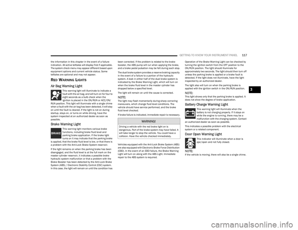
RED WARNING LIGHTS
Air Bag Warning Light
This warning light will illuminate to indicate a
fault with the air bag, and will turn on for four to
eight seconds as a bulb check when the
ignition is placed in the ON/RUN or ACC/ON/
RUN position. This light will illuminate with a single chime
when a fault with the air bag has been detected, it will stay
on until the fault is cleared. If the light is not on during
startup, stays on, or turns on while driving, have the
system inspected at an authorized dealer as soon as
possible.
Brake Warning Light
This warning light monitors various brake
functions, including brake fluid level and
parking brake application. If the brake light
turns on it may indicate that the parking brake
is applied, that the brake fluid level is low, or that there is
a problem with the Anti-Lock Brake System reservoir.
If the light remains on when the parking brake has been
disengaged, and the fluid level is at the full mark on the
master cylinder reservoir, it indicates a possible brake
hydraulic system malfunction or that a problem with the
Brake Booster has been detected by the Anti-Lock Brake
System (ABS) / Electronic Stability Control (ESC) system.
In this case, the light will remain on until the condition has been corrected. If the problem is related to the brake
booster, the ABS pump will run when applying the brake,
and a brake pedal pulsation may be felt during each stop.
The dual brake system provides a reserve braking capacity
in the event of a failure to a portion of the hydraulic
system. A leak in either half of the dual brake system is
indicated by the Brake Warning Light, which will turn on
when the brake fluid level in the master cylinder has
dropped below a specified level.
The light will remain on until the cause is corrected.
NOTE:The light may flash momentarily during sharp cornering
maneuvers, which change fluid level conditions. The
vehicle should have service performed, and the brake
fluid level checked.
If brake failure is indicated, immediate repair is necessary.
Vehicles equipped with the Anti-Lock Brake System (ABS)
are also equipped with Electronic Brake Force Distribution
(EBD). In the event of an EBD failure, the Brake Warning
Light will turn on along with the ABS Light. Immediate
repair to the ABS system is required.
Operation of the Brake Warning Light can be checked by
turning the ignition switch from the OFF position to the
ON/RUN position. The light should illuminate for
approximately two seconds. The light should then turn off
unless the parking brake is applied or a brake fault is
detected. If the light does not illuminate, have the light
inspected by an authorized dealer.
The light also will turn on when the parking brake is
applied with the ignition switch in the ON/RUN position.
NOTE:This light shows only that the parking brake is applied. It
does not show the degree of brake application.
Battery Charge Warning Light
This warning light will illuminate when the
battery is not charging properly. If it stays on
while the engine is running, there may be a
malfunction with the charging system. Contact
an authorized dealer as soon as possible.
This indicates a possible problem with the electrical
system or a related component.
Door Open Warning Light
This indicator will illuminate when a door is
ajar/open and not fully closed.
NOTE:If the vehicle is moving, there will also be a single chime.
WARNING!
Driving a vehicle with the red brake light on is
dangerous. Part of the brake system may have failed. It
will take longer to stop the vehicle. You could have a
collision. Have the vehicle checked immediately.
3
23_JL_OM_EN_USC_t.book Page 117
Page 120 of 396
118GETTING TO KNOW YOUR INSTRUMENT PANEL
Electric Power Steering (EPS) Fault
Warning Light
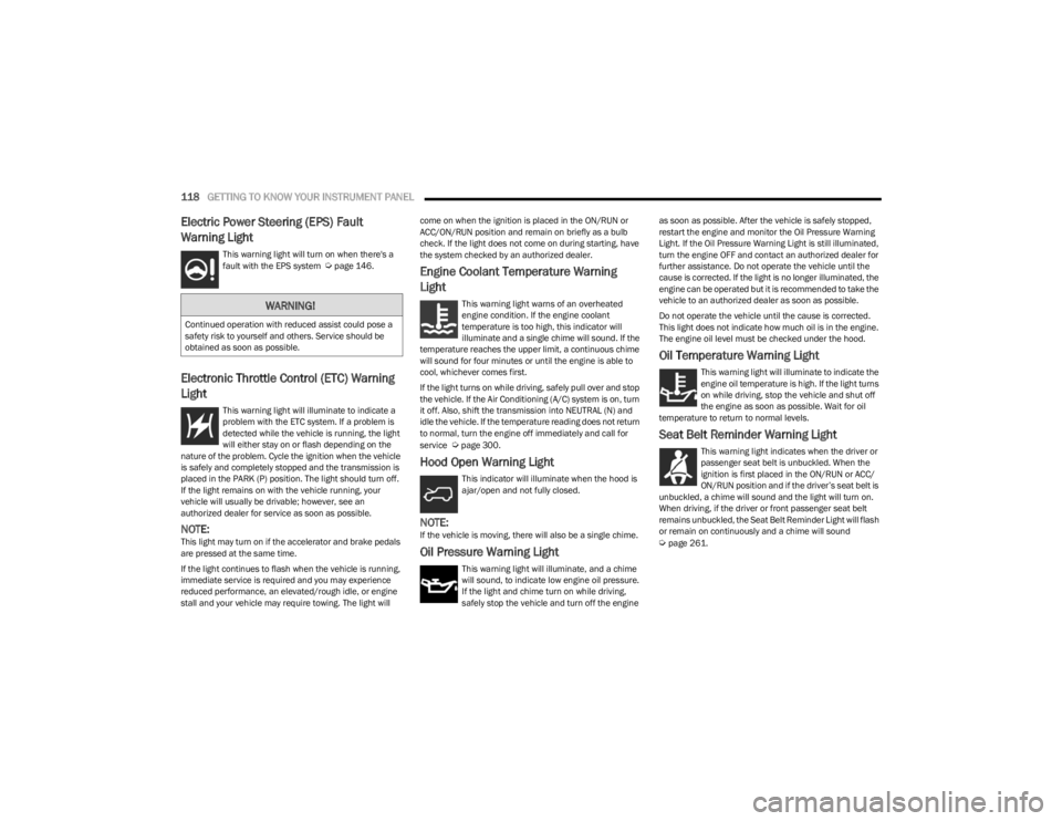
This warning light will turn on when there's a
fault with the EPS system Úpage 146.
Electronic Throttle Control (ETC) Warning
Light
This warning light will illuminate to indicate a
problem with the ETC system. If a problem is
detected while the vehicle is running, the light
will either stay on or flash depending on the
nature of the problem. Cycle the ignition when the vehicle
is safely and completely stopped and the transmission is
placed in the PARK (P) position. The light should turn off.
If the light remains on with the vehicle running, your
vehicle will usually be drivable; however, see an
authorized dealer for service as soon as possible.
NOTE:This light may turn on if the accelerator and brake pedals
are pressed at the same time.
If the light continues to flash when the vehicle is running,
immediate service is required and you may experience
reduced performance, an elevated/rough idle, or engine
stall and your vehicle may require towing. The light will come on when the ignition is placed in the ON/RUN or
ACC/ON/RUN position and remain on briefly as a bulb
check. If the light does not come on during starting, have
the system checked by an authorized dealer.
Engine Coolant Temperature Warning
Light
This warning light warns of an overheated
engine condition. If the engine coolant
temperature is too high, this indicator will
illuminate and a single chime will sound. If the
temperature reaches the upper limit, a continuous chime
will sound for four minutes or until the engine is able to
cool, whichever comes first.
If the light turns on while driving, safely pull over and stop
the vehicle. If the Air Conditioning (A/C) system is on, turn
it off. Also, shift the transmission into NEUTRAL (N) and
idle the vehicle. If the temperature reading does not return
to normal, turn the engine off immediately and call for
service
Úpage 300.
Hood Open Warning Light
This indicator will illuminate when the hood is
ajar/open and not fully closed.
NOTE:If the vehicle is moving, there will also be a single chime.
Oil Pressure Warning Light
This warning light will illuminate, and a chime
will sound, to indicate low engine oil pressure.
If the light and chime turn on while driving,
safely stop the vehicle and turn off the engine as soon as possible. After the vehicle is safely stopped,
restart the engine and monitor the Oil Pressure Warning
Light. If the Oil Pressure Warning Light is still illuminated,
turn the engine OFF and contact an authorized dealer for
further assistance. Do not operate the vehicle until the
cause is corrected. If the light is no longer illuminated, the
engine can be operated but it is recommended to take the
vehicle to an authorized dealer as soon as possible.
Do not operate the vehicle until the cause is corrected.
This light does not indicate how much oil is in the engine.
The engine oil level must be checked under the hood.
Oil Temperature Warning Light
This warning light will illuminate to indicate the
engine oil temperature is high. If the light turns
on while driving, stop the vehicle and shut off
the engine as soon as possible. Wait for oil
temperature to return to normal levels.
Seat Belt Reminder Warning Light
This warning light indicates when the driver or
passenger seat belt is unbuckled. When the
ignition is first placed in the ON/RUN or ACC/
ON/RUN position and if the driver’s seat belt is
unbuckled, a chime will sound and the light will turn on.
When driving, if the driver or front passenger seat belt
remains unbuckled, the Seat Belt Reminder Light will flash
or remain on continuously and a chime will sound
Úpage 261.
WARNING!
Continued operation with reduced assist could pose a
safety risk to yourself and others. Service should be
obtained as soon as possible.
23_JL_OM_EN_USC_t.book Page 118
Page 123 of 396
GETTING TO KNOW YOUR INSTRUMENT PANEL121
Service Forward Collision Warning (FCW)
Light — If Equipped
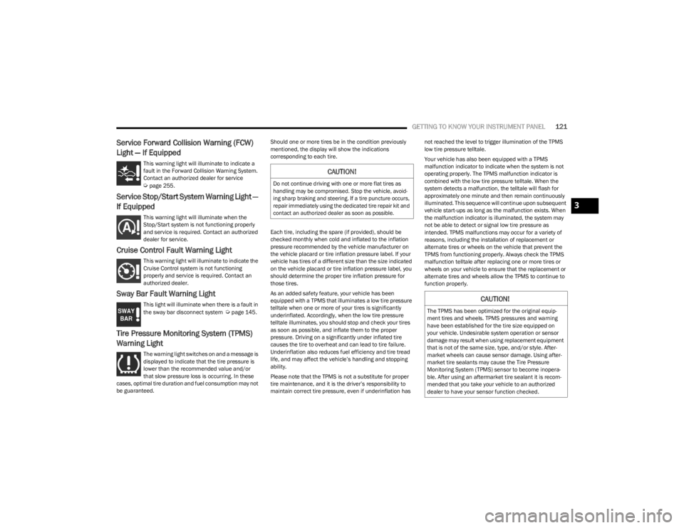
This warning light will illuminate to indicate a
fault in the Forward Collision Warning System.
Contact an authorized dealer for service
Úpage 255.
Service Stop/Start System Warning Light —
If Equipped
This warning light will illuminate when the
Stop/Start system is not functioning properly
and service is required. Contact an authorized
dealer for service.
Cruise Control Fault Warning Light
This warning light will illuminate to indicate the
Cruise Control system is not functioning
properly and service is required. Contact an
authorized dealer.
Sway Bar Fault Warning Light
This light will illuminate when there is a fault in
the sway bar disconnect system Úpage 145.
Tire Pressure Monitoring System (TPMS)
Warning Light
The warning light switches on and a message is
displayed to indicate that the tire pressure is
lower than the recommended value and/or
that slow pressure loss is occurring. In these
cases, optimal tire duration and fuel consumption may not
be guaranteed. Should one or more tires be in the condition previously
mentioned, the display will show the indications
corresponding to each tire.
Each tire, including the spare (if provided), should be
checked monthly when cold and inflated to the inflation
pressure recommended by the vehicle manufacturer on
the vehicle placard or tire inflation pressure label. If your
vehicle has tires of a different size than the size indicated
on the vehicle placard or tire inflation pressure label, you
should determine the proper tire inflation pressure for
those tires.
As an added safety feature, your vehicle has been
equipped with a TPMS that illuminates a low tire pressure
telltale when one or more of your tires is significantly
underinflated. Accordingly, when the low tire pressure
telltale illuminates, you should stop and check your tires
as soon as possible, and inflate them to the proper
pressure. Driving on a significantly under inflated tire
causes the tire to overheat and can lead to tire failure.
Underinflation also reduces fuel efficiency and tire tread
life, and may affect the vehicle’s handling and stopping
ability.
Please note that the TPMS is not a substitute for proper
tire maintenance, and it is the driver’s responsibility to
maintain correct tire pressure, even if underinflation has not reached the level to trigger illumination of the TPMS
low tire pressure telltale.
Your vehicle has also been equipped with a TPMS
malfunction indicator to indicate when the system is not
operating properly. The TPMS malfunction indicator is
combined with the low tire pressure telltale. When the
system detects a malfunction, the telltale will flash for
approximately one minute and then remain continuously
illuminated. This sequence will continue upon subsequent
vehicle start-ups as long as the malfunction exists. When
the malfunction indicator is illuminated, the system may
not be able to detect or signal low tire pressure as
intended. TPMS malfunctions may occur for a variety of
reasons, including the installation of replacement or
alternate tires or wheels on the vehicle that prevent the
TPMS from functioning properly. Always check the TPMS
malfunction telltale after replacing one or more tires or
wheels on your vehicle to ensure that the replacement or
alternate tires and wheels allow the TPMS to continue to
function properly.
CAUTION!
Do not continue driving with one or more flat tires as
handling may be compromised. Stop the vehicle, avoid
-
ing sharp braking and steering. If a tire puncture occurs,
repair immediately using the dedicated tire repair kit and
contact an authorized dealer as soon as possible.
CAUTION!
The TPMS has been optimized for the original equip -
ment tires and wheels. TPMS pressures and warning
have been established for the tire size equipped on
your vehicle. Undesirable system operation or sensor
damage may result when using replacement equipment
that is not of the same size, type, and/or style. After -
market wheels can cause sensor damage. Using after -
market tire sealants may cause the Tire Pressure
Monitoring System (TPMS) sensor to become inopera -
ble. After using an aftermarket tire sealant it is recom -
mended that you take your vehicle to an authorized
dealer to have your sensor function checked.
3
23_JL_OM_EN_USC_t.book Page 121
Page 125 of 396
GETTING TO KNOW YOUR INSTRUMENT PANEL123
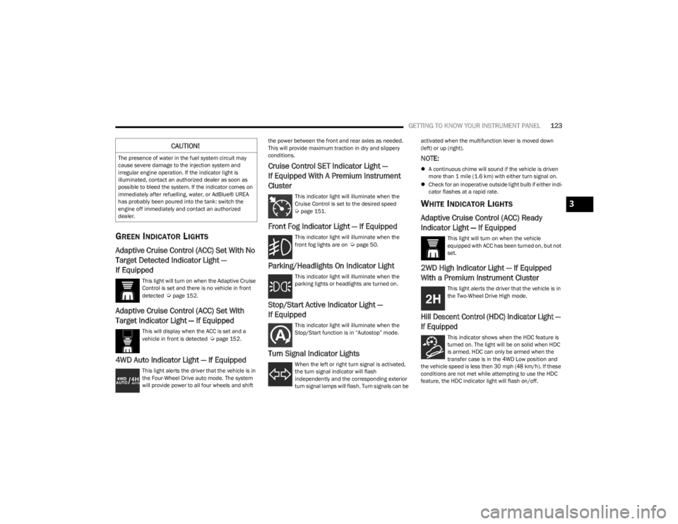
GREEN INDICATOR LIGHTS
Adaptive Cruise Control (ACC) Set With No
Target Detected Indicator Light —
If Equipped
This light will turn on when the Adaptive Cruise
Control is set and there is no vehicle in front
detected
Úpage 152.
Adaptive Cruise Control (ACC) Set With
Target Indicator Light — If Equipped
This will display when the ACC is set and a
vehicle in front is detected Úpage 152.
4WD Auto Indicator Light — If Equipped
This light alerts the driver that the vehicle is in
the Four-Wheel Drive auto mode. The system
will provide power to all four wheels and shift the power between the front and rear axles as needed.
This will provide maximum traction in dry and slippery
conditions.
Cruise Control SET Indicator Light —
If Equipped With A Premium Instrument
Cluster
This indicator light will illuminate when the
Cruise Control is set to the desired speed
Úpage 151.
Front Fog Indicator Light — If Equipped
This indicator light will illuminate when the
front fog lights are on Úpage 50.
Parking/Headlights On Indicator Light
This indicator light will illuminate when the
parking lights or headlights are turned on.
Stop/Start Active Indicator Light —
If Equipped
This indicator light will illuminate when the
Stop/Start function is in “Autostop” mode.
Turn Signal Indicator Lights
When the left or right turn signal is activated,
the turn signal indicator will flash
independently and the corresponding exterior
turn signal lamps will flash. Turn signals can be activated when the multifunction lever is moved down
(left) or up (right).
NOTE:
A continuous chime will sound if the vehicle is driven
more than 1 mile (1.6 km) with either turn signal on.
Check for an inoperative outside light bulb if either indi -
cator flashes at a rapid rate.
WHITE INDICATOR LIGHTS
Adaptive Cruise Control (ACC) Ready
Indicator Light — If Equipped
This light will turn on when the vehicle
equipped with ACC has been turned on, but not
set.
2WD High Indicator Light — If Equipped
With a Premium Instrument Cluster
This light alerts the driver that the vehicle is in
the Two-Wheel Drive High mode.
Hill Descent Control (HDC) Indicator Light —
If Equipped
This indicator shows when the HDC feature is
turned on. The light will be on solid when HDC
is armed. HDC can only be armed when the
transfer case is in the 4WD Low position and
the vehicle speed is less then 30 mph (48 km/h). If these
conditions are not met while attempting to use the HDC
feature, the HDC indicator light will flash on/off.
CAUTION!
The presence of water in the fuel system circuit may
cause severe damage to the injection system and
irregular engine operation. If the indicator light is
illuminated, contact an authorized dealer as soon as
possible to bleed the system. If the indicator comes on
immediately after refuelling, water, or AdBlue® UREA
has probably been poured into the tank: switch the
engine off immediately and contact an authorized
dealer.
3
23_JL_OM_EN_USC_t.book Page 123
Page 128 of 396
126
STARTING AND OPERATING
STARTING THE ENGINE — GASOLINE
ENGINE (IF EQUIPPED)
Before starting your vehicle, adjust your seat, adjust both
inside and outside mirrors, and fasten your seat belts.
MANUAL TRANSMISSION — IF EQUIPPED
Apply the parking brake, place the gear selector in
NEUTRAL, and press the clutch pedal before starting the
vehicle. This vehicle is equipped with a clutch interlocking
ignition system. It will not start unless the clutch pedal is
pressed to the floor.
Four-Wheel Drive Models Only
In 4L mode, if the vehicle is stalled, the engine will start
regardless of whether or not the clutch pedal is pressed to
the floor. This feature enhances off-road performance by
allowing the vehicle to start when in 4L without having to
press the clutch pedal. The 4L Indicator Light will
illuminate when the transfer case has been shifted into
this mode.
AUTOMATIC TRANSMISSION —
I
F EQUIPPED
Start the vehicle with the gear selector in the PARK
position (vehicle can also be started in NEUTRAL). Apply
the brake before shifting to any driving range.
NORMAL STARTING
To Turn On The Engine Using The ENGINE START/STOP
Button
1. The transmission must be in PARK or NEUTRAL.
2. Press and hold the brake pedal while pushing the
ENGINE START/STOP button once. 3. The system takes over and attempts to start the
vehicle. If the vehicle fails to start, the starter will
disengage automatically after 10 seconds.
4. If you wish to stop the cranking of the engine prior to the engine starting, push the button again.
NOTE:Normal starting of either a cold or a warm engine is
obtained without pumping or pressing the accelerator
pedal.
To Turn Off The Engine Using The ENGINE START/STOP
Button
1. Place the gear selector in PARK, then push and release the ENGINE START/STOP button.
2. The ignition will return to the OFF position.
3. If the gear selector is not in PARK (with vehicle stopped) and the ENGINE START/STOP button is
pushed once, the transmission will automatically
select PARK and the engine will turn off while the
ignition will remain in the ACC position (NOT the OFF
position). Never leave a vehicle out of the PARK
position, or it could roll.
4. If the gear selector is in NEUTRAL, and the vehicle speed is below 5 mph (8 km/h), pushing the START/
STOP button once will turn the engine off. The ignition
will remain in the ACC position.
5. If the vehicle speed is above 5 mph (8 km/h), the ENGINE START/STOP button must be held for two WARNING!
When exiting the vehicle, always remove the key fob
from the ignition and lock your vehicle.
Never leave children alone in a vehicle, or with
access to an unlocked vehicle.
Allowing children to be in a vehicle unattended is
dangerous for a number of reasons. A child or others
could be seriously or fatally injured. Children should
be warned not to touch the parking brake, brake
pedal or the gear selector.
Do not leave the key fob in or near the vehicle, or in
a location accessible to children. A child could
operate power windows, other controls, or move the
vehicle.
Do not leave children or animals inside parked vehi -
cles in hot weather. Interior heat buildup may cause
serious injury or death.
23_JL_OM_EN_USC_t.book Page 126