stop start JEEP WRANGLER 2023 Service Manual
[x] Cancel search | Manufacturer: JEEP, Model Year: 2023, Model line: WRANGLER, Model: JEEP WRANGLER 2023Pages: 396, PDF Size: 25.15 MB
Page 157 of 396
STARTING AND OPERATING155
If ACC is set when the vehicle speed is below 20 mph
(32 km/h), the set speed will default to 20 mph
(32 km/h).
NOTE:Fixed Speed Cruise Control cannot be set below 20 mph
(32 km/h).
If either system is set when the vehicle speed is above
20 mph (32 km/h), the set speed shall be the current speed of the vehicle.
On vehicles equipped with a manual transmission, the
ACC system cannot be set when the vehicle speed is below
20 mph (32 km/h) or when the vehicle is in FIRST gear.
NOTE:
Keeping your foot on the accelerator pedal can cause
the vehicle to continue to accelerate beyond the set
speed. If this occurs, the message “DRIVER OVERRIDE”
will display in the instrument cluster display.
If you continue to accelerate beyond the set speed
while ACC is enabled, the system will not be controlling
the distance between your vehicle and the vehicle
ahead. The vehicle speed will only be determined by
the position of the accelerator pedal.
To Cancel
The following conditions cancel the ACC or Fixed Speed
Cruise Control systems:
The brake pedal is applied
The CANC button is pushed
The Anti-Lock Brake System (ABS) activates
The gear selector is removed from the DRIVE position
The Electronic Stability Control/Traction Control
System (ESC/TCS) activates
The vehicle parking brake is applied
The braking temperature exceeds normal range (over -
heated)
The Trailer Sway Control (TSC) activates
The vehicle speed is less than 15 mph (24 km/h)
(manual transmission only)
The clutch is pressed for more than 10 seconds
(manual transmission only)
The vehicle is placed in NEUTRAL for more than
10 seconds (manual transmission only)
The driver shifts to FIRST gear (manual transmission
only)
The following conditions will only cancel the ACC system:
Driver seat belt is unbuckled at low speeds
Driver door is opened at low speeds
To Turn Off
The system will turn off and erase the set speed in
memory if:
The Adaptive Cruise Control (ACC) on/off button is
pushed
The Fixed Speed Cruise Control on/off button is pushed
The ignition is placed in the OFF position
4WD Low is engaged
To Resume
If there is a set speed in the memory, push the RES button
and then remove your foot from the accelerator pedal. The
instrument cluster display will show the last set speed. Resume can be used at any speed above 20 mph
(32 km/h) when only Fixed Speed Cruise Control is being
used.
Resume can be used at any speed above 0 mph (0 km/h)
when ACC is active.
NOTE:
While in ACC mode, when the vehicle comes to a
complete stop longer than two seconds, the system will
cancel. The driver will have to apply the brakes to keep
the vehicle at a standstill.
ACC cannot be resumed if there is a stationary vehicle
in front of your vehicle in close proximity.
To Vary The Speed Setting
To Increase Or Decrease The Set Speed
After setting a speed, you can increase the set speed by
pushing the SET (+) button, or decrease speed by pushing
the SET (-) button.
WARNING!
The Resume function should only be used if traffic and
road conditions permit. Resuming a set speed that is
too high or too low for prevailing traffic and road condi -
tions could cause the vehicle to accelerate or deceler -
ate too sharply for safe operation. Failure to follow
these warnings can result in a collision and death or
serious personal injury.
4
23_JL_OM_EN_USC_t.book Page 155
Page 158 of 396
156STARTING AND OPERATING
U.S. Speed (mph)
Pushing the SET (+), or SET (-) button once will result in
a 1 mph speed adjustment. Each subsequent tap of
the button results in an adjustment of 1 mph.
If the button is continually pushed, the set speed will
continue to adjust in 5 mph increments until the button
is released. The new set speed is reflected in the instru -
ment cluster display.
Metric Speed (km/h)
Pushing the SET (+), or SET (-) button once will result in
a 1 km/h speed adjustment. Each subsequent tap of
the button results in an adjustment of 1 km/h.
If the button is continually pushed, the set speed will
continue to adjust in 10 km/h increments until the
button is released. The new set speed is reflected in
the instrument cluster display.
NOTE:When you override and push the SET (+) button or SET (-)
buttons, the new set speed will be the current speed of the
vehicle.
When ACC Is Active
When you use the SET (-) button to decelerate, if the
engine’s braking power does not slow the vehicle suffi -
ciently to reach the set speed, the brake system will
automatically slow the vehicle.
The ACC system applies the brake down to a full stop
when following the vehicle in front. If your vehicle
follows the vehicle in front to a standstill, your vehicle
will release the brakes two seconds after coming to a
full stop.
The ACC system maintains set speed when driving
uphill and downhill. However, a slight speed change on moderate hills is normal. In addition, downshifting may
occur while climbing uphill or descending downhill. This
is normal operation and necessary to maintain set
speed. When driving uphill and downhill, the ACC
system will cancel if the braking temperature exceeds
normal range (overheated).
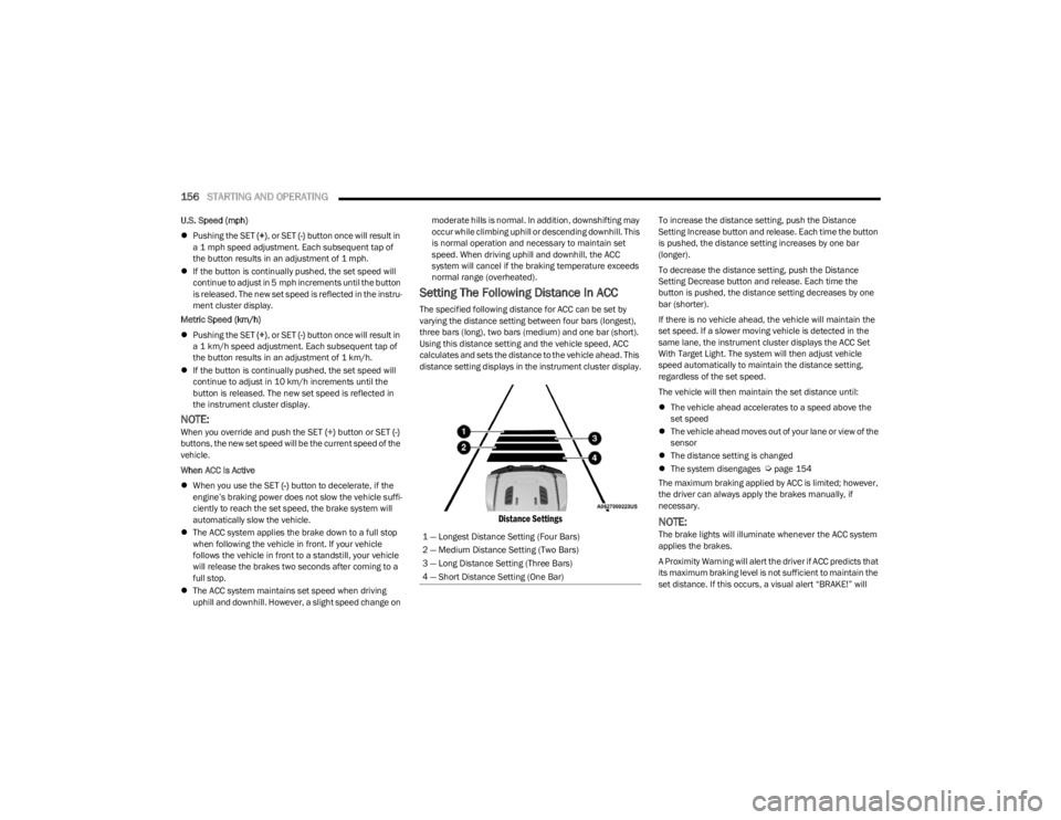
Setting The Following Distance In ACC
The specified following distance for ACC can be set by
varying the distance setting between four bars (longest),
three bars (long), two bars (medium) and one bar (short).
Using this distance setting and the vehicle speed, ACC
calculates and sets the distance to the vehicle ahead. This
distance setting displays in the instrument cluster display.
Distance Settings
To increase the distance setting, push the Distance
Setting Increase button and release. Each time the button
is pushed, the distance setting increases by one bar
(longer).
To decrease the distance setting, push the Distance
Setting Decrease button and release. Each time the
button is pushed, the distance setting decreases by one
bar (shorter).
If there is no vehicle ahead, the vehicle will maintain the
set speed. If a slower moving vehicle is detected in the
same lane, the instrument cluster displays the ACC Set
With Target Light. The system will then adjust vehicle
speed automatically to maintain the distance setting,
regardless of the set speed.
The vehicle will then maintain the set distance until:
The vehicle ahead accelerates to a speed above the
set speed
The vehicle ahead moves out of your lane or view of the
sensor
The distance setting is changed
The system disengages
Úpage 154
The maximum braking applied by ACC is limited; however,
the driver can always apply the brakes manually, if
necessary.
NOTE:The brake lights will illuminate whenever the ACC system
applies the brakes.
A Proximity Warning will alert the driver if ACC predicts that
its maximum braking level is not sufficient to maintain the
set distance. If this occurs, a visual alert “BRAKE!” will
1 — Longest Distance Setting (Four Bars)
2 — Medium Distance Setting (Two Bars)
3 — Long Distance Setting (Three Bars)
4 — Short Distance Setting (One Bar)
23_JL_OM_EN_USC_t.book Page 156
Page 159 of 396
STARTING AND OPERATING157
flash in the instrument cluster display and a chime will
sound while ACC continues to apply its maximum braking
capacity.
NOTE:The “BRAKE!” screen in the instrument cluster display is a
warning for the driver to take action and does not neces -
sarily mean that the Forward Collision Warning system is
applying the brakes autonomously.
Overtake Aid
When driving with ACC engaged and following a vehicle,
the system will provide an additional acceleration up to
the ACC set speed to assist in passing the vehicle. This
additional acceleration is triggered when the driver utilizes
the left turn signal and will only be active when passing on
the left hand side.
ACC Operation At A Stop (Automatic
Transmission Only)
In the event that the ACC system brings your vehicle to a
standstill while following a target vehicle, your vehicle will
resume motion without the need for any driver action if the
target vehicle starts moving within two seconds of your
vehicle coming to a standstill.
If the target vehicle does not start moving within two
seconds of your vehicle coming to a standstill, the ACC
with Stop system will cancel and the brakes will release. A
cancel message will display on the instrument cluster
display and produce a warning chime. Driver intervention
will be required at this moment.
While ACC with Stop is holding your vehicle at a standstill,
if the driver seatbelt is unbuckled or the driver door is
opened, the ACC with Stop system will cancel and the brakes will release. A cancel message will display on the
instrument cluster display and produce a warning chime.
Driver intervention will be required at this moment.
Display Warnings And Maintenance
“WIPE FRONT RADAR SENSOR IN FRONT OF
VEHICLE” WARNING
The “ACC/FCW Unavailable Wipe Front Radar Sensor”
warning will display and a chime will sound when
conditions temporarily limit system performance.
This most often occurs at times of poor visibility, such as
in snow or heavy rain. The ACC system may also become
temporarily blinded due to obstructions, such as mud, dirt
or ice. In these cases, the instrument cluster display will
display “ACC/FCW Unavailable Wipe Front Radar Sensor”
and the system will deactivate.
The “ACC/FCW Unavailable Wipe Front Radar Sensor”
message can sometimes be displayed while driving in
highly reflective areas (i.e. tunnels with reflective tiles, or
ice and snow). The ACC system will recover after the
vehicle has left these areas. Under rare conditions, when
the radar is not tracking any vehicles or objects in its path
this warning may temporarily occur.
NOTE:If the “ACC/FCW Unavailable Wipe Front Radar Sensor”
warning is active, Fixed Speed Cruise Control is still
available.
If weather conditions are not a factor, the driver should
examine the sensor. It may require cleaning or removal of
an obstruction. The sensor is located in the center of the
vehicle behind the lower grille.
To keep the ACC system operating properly, it is important
to note the following maintenance items:
Always keep the sensor clean. Carefully wipe the
sensor lens with a soft cloth. Be cautious not to
damage the sensor lens.
Do not remove any screws from the sensor. Doing so
could cause an ACC system malfunction or failure and
require a sensor realignment.
If the sensor or front end of the vehicle is damaged due
to a collision, see an authorized dealer for service.
Do not attach or install any accessories near the
sensor, including transparent material or aftermarket
grilles. Doing so could cause an ACC system failure or
malfunction.
When the condition that deactivated the system is no
longer present, the system will return to the “Adaptive
Cruise Control Off” state and will resume function by
simply reactivating it.
NOTE:If the “ACC/FCW Unavailable Wipe Front Radar Sensor”
message occurs frequently (e.g. more than once on every
trip) without any snow, rain, mud, or other obstruction,
have the radar sensor realigned at an authorized dealer.
WARNING!
When the ACC system is resumed, the driver must
ensure that there are no pedestrians, vehicles or
objects in the path of the vehicle. Failure to follow these
warnings can result in a collision and death or serious
personal injury.
4
23_JL_OM_EN_USC_t.book Page 157
Page 161 of 396
STARTING AND OPERATING159
USING ACC ON HILLS
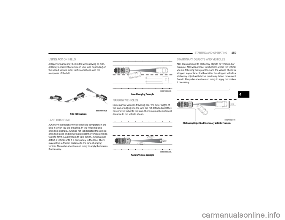
ACC performance may be limited when driving on hills.
ACC may not detect a vehicle in your lane depending on
the speed, vehicle load, traffic conditions, and the
steepness of the hill.
ACC Hill Example
LANE CHANGING
ACC may not detect a vehicle until it is completely in the
lane in which you are traveling. In the following lane
changing example, ACC has not yet detected the vehicle
changing lanes and it may not detect the vehicle until it's
too late for the ACC system to take action. ACC may not
detect a vehicle until it is completely in the lane. There
may not be sufficient distance to the lane-changing
vehicle. Always be attentive and ready to apply the brakes
if necessary.
Lane Changing Example
NARROW VEHICLES
Some narrow vehicles traveling near the outer edges of
the lane or edging into the lane are not detected until they
have moved fully into the lane. There may not be sufficient
distance to the vehicle ahead.
Narrow Vehicle Example
STATIONARY OBJECTS AND VEHICLES
ACC does not react to stationary objects or vehicles. For
example, ACC will not react in situations where the vehicle
you are following exits your lane and the vehicle ahead is
stopped in your lane. It will consider this stopped vehicle a
stationary object as it did not previously detect movement
from it. Always be attentive and ready to apply the brakes
if necessary.
Stationary Object And Stationary Vehicle Example
4
23_JL_OM_EN_USC_t.book Page 159
Page 165 of 396
STARTING AND OPERATING163
CLEANING THE PARKSENSE SYSTEM
Clean the Rear Park Assist sensors with water, car wash
soap and a soft cloth. Do not use rough or hard cloths. In
washing stations, clean sensors quickly keeping the vapor
jet/high pressure washing nozzles at least 4 inches (10
cm) from the sensors. Do not scratch or poke the sensors.
PARKSENSE SYSTEM USAGE
P
RECAUTIONS
NOTE:
Ensure that the rear fascia/bumper is free of snow, ice,
mud, dirt and debris to keep the ParkSense system
operating properly.
Jackhammers, large trucks, and other vibrations could
affect the performance of ParkSense.
When you turn ParkSense off, the instrument cluster
display will read “PARKSENSE OFF.” Furthermore, once
you turn ParkSense off, it remains off until you turn it
on again, even if you cycle the ignition.
ParkSense, when on, will reduce the volume of the
radio when it is sounding a tone.
Clean the ParkSense sensors regularly, taking care not
to scratch or damage them. The sensors must not be
covered with ice, snow, slush, mud, dirt or debris.
Failure to do so can result in the system not working
properly. The ParkSense system might not detect an
obstacle behind the fascia/bumper, or it could provide
a false indication that an obstacle is behind the fascia/
bumper.
Use the ParkSense switch to turn the ParkSense
system off if objects such as bicycle carriers, trailer
hitches, etc. are placed within 12 inches (30 cm) of the
rear fascia/bumper. Failure to do so can result in the
system misinterpreting a close object as a sensor
problem, causing the “PARKSENSE UNAVAILABLE
SERVICE REQUIRED” message to be displayed in the
instrument cluster display.
PARKVIEW REAR BACK UP CAMERA
The ParkView Rear Back Up Camera allows you to see an
on-screen image of the rear surroundings of your vehicle
whenever the gear selector is put into REVERSE. The
image will be displayed in the touchscreen display along
with a caution note to “Check Entire Surroundings” across
the top of the screen. After five seconds this note will
disappear. The ParkView camera is located on the rear of
the vehicle in the center of the spare tire.
Manual Activation Of The Rear View Camera
1. Press the Controls button located on the bottom of
the Uconnect display.
2. Press the Back Up Camera button to turn the Rear View Camera system on.
WARNING!
Drivers must be careful when backing up even when
using ParkSense. Always check carefully behind your
vehicle, look behind you, and be sure to check for
pedestrians, animals, other vehicles, obstructions,
and blind spots before backing up. You are respon -
sible for safety and must continue to pay attention to
your surroundings. Failure to do so can result in
serious injury or death.
Before using ParkSense, it is strongly recommended
that the ball mount and hitch ball assembly be
disconnected from the vehicle when the vehicle is
not used for towing. Failure to do so can result in
injury or damage to vehicles or obstacles because
the hitch ball will be much closer to the obstacle than
the rear fascia when the vehicle sounds the contin -
uous tone. Also, the sensors could detect the ball
mount and hitch ball assembly, depending on its size
and shape, giving a false indication that an obstacle
is behind the vehicle.
CAUTION!
ParkSense is only a parking aid and it is unable to
recognize every obstacle, including small obstacles.
Parking curbs might be temporarily detected or not
detected at all. Obstacles located above or below the
sensors will not be detected when they are in close
proximity.
The vehicle must be driven slowly when using Park -
Sense in order to be able to stop in time when an
obstacle is detected. It is recommended that the
driver looks over his/her shoulder when using Park -
Sense.
4
23_JL_OM_EN_USC_t.book Page 163
Page 166 of 396
164STARTING AND OPERATING
(Continued)
When the vehicle is shifted out of REVERSE with Camera
delay turned off, the rear Camera mode is exited and the
previous screen appears again.
When the vehicle is shifted out of REVERSE with Camera
delay turned on, the rear Camera image will be displayed
for up to 10 seconds unless the vehicle speed exceeds
8 mph (13 km/h), the transmission is shifted into PARK,
the ignition is placed in the OFF position, or the
touchscreen X button to disable display of the Rear View
Camera image is pressed.
Whenever the Rear View Camera image is activated
through the Back Up Camera button in the Controls menu,
and the vehicle speed is greater than, or equal to, 8 mph
(13 km/h), a display timer for the image is initiated. The
image will continue to be displayed until the display timer
exceeds 10 seconds.
NOTE:
If the vehicle speed remains below 8 mph (13 km/h),
the Rear View Camera image will be displayed continu -
ously until deactivated via the touchscreen X button,
the transmission is shifted into PARK, or the ignition is
placed in the OFF position.
The touchscreen X button to disable display of the
camera image is made available ONLY when the
vehicle is not in REVERSE.
When enabled, active guidelines are overlaid on the image
to illustrate the width of the vehicle and its projected back
up path based on the steering wheel position. A dashed
center line overlay indicates the center of the vehicle to
assist with parking or aligning to a hitch/receiver.
When enabled, fixed guidelines are overlaid on the image
to illustrate the width of the vehicle. Different colored zones indicate the distance to the rear of
the vehicle.
The following table shows the approximate distances for
each zone:
NOTE:If snow, ice, mud, or any foreign substance builds up on
the camera lens, clean the lens, rinse with water, and dry
with a soft cloth. Do not cover the lens.
TRAILCAM SYSTEM — IF EQUIPPED
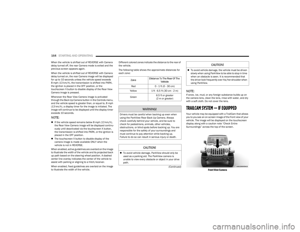
Your vehicle may be equipped with a TrailCam that allows
you to you see an on-screen image of the front view of your
vehicle. The image will be displayed on the touchscreen
display along with a caution note “Check Entire
Surroundings” across the top of the screen.
Front View Camera
Zone
Distance To The Rear Of The
Vehicle
Red 0 - 1 ft (0 - 30 cm)
Yellow 1 ft - 6.5 ft (30 cm - 2 m)
Green 6.5 ft or greater
(2 m or greater)
WARNING!
Drivers must be careful when backing up even when
using the ParkView Rear Back Up Camera. Always
check carefully behind your vehicle, and be sure to
check for pedestrians, animals, other vehicles,
obstructions, or blind spots before backing up. You are
responsible for the safety of your surroundings and
must continue to pay attention while backing up.
Failure to do so can result in serious injury or death.
CAUTION!
To avoid vehicle damage, ParkView should only be
used as a parking aid. The ParkView camera is
unable to view every obstacle or object in your drive
path.
To avoid vehicle damage, the vehicle must be driven
slowly when using ParkView to be able to stop in time
when an obstacle is seen. It is recommended that
the driver look frequently over his/her shoulder when
using ParkView.
CAUTION!
23_JL_OM_EN_USC_t.book Page 164
Page 167 of 396
STARTING AND OPERATING165
NOTE:The system will stay active while in 4WD Low.
The TrailCam system has programmable settings that may
be selected through the Uconnect system
Úpage 184.
Manual Activation Of The TrailCam
TrailCam view can be activated via the below methods:
Press the FWD Camera button on the controls screen.
Press the Forward Facing Camera button on the apps
menu.
Press the TrailCam button on the Off Road Pages.
Press the Off Road+ button when “Auto Launch Off
Road+” (if equipped) has been selected under camera
settings.
The TrailCam view can also be activated by pressing the icon on the Back Up Camera view. The Back Up
Camera view can also be activated by pressing the
icon on the TrailCam view.
When the vehicle is shifted out of REVERSE with Camera
Delay turned off and TrailCam view is active, the TrailCam
mode is exited and the previous screen appears again.
When the vehicle is shifted out of REVERSE with Camera
Delay turned on and the TrailCam view is active, the
TrailCam image will be displayed for up to 10 seconds
unless the vehicle speed exceeds 8 mph (13 km/h), the
transmission is shifted into PARK, the ignition is placed in
the OFF position, or the touchscreen X button to disable
display of the TrailCam view is pressed.
Whenever the TrailCam image is activated through the
Manual Activation Methods, and the vehicle speed is
greater than or equal to 8 mph (13 km/h), a display timer for the image is initiated. The image will continue to be
displayed until the display timer exceeds 10 seconds.
NOTE:
If the vehicle speed remains below 8 mph (13 km/h)
while in 2WD or 4WD High, the TrailCam image will be
displayed continuously until deactivated via the touch -
screen X button, the transmission is shifted into PARK,
or the ignition is placed in the OFF position.
The touchscreen X button to disable the display of the
camera image is made available ONLY when the
vehicle is not in REVERSE.
The TrailCam view will stay active regardless of the
vehicle speed and time while in 4WD Low.
Cleaning The TrailCam
Press and hold the Clean Camera button located on the
TrailCam view to wash the TrailCam. Washer fluid will stop
when the button is released.
The camera can be washed up to 20 seconds at a time
while holding the button.
The Clean Camera system is not available when wind -
shield washing is in process.
When enabled, active dynamic tire lines are projected on
the ground plane of the TrailCam view based on the
steering wheel position.
REFUELING THE VEHICLE — GASOLINE
ENGINE (IF EQUIPPED)
FUEL FILLER CAP
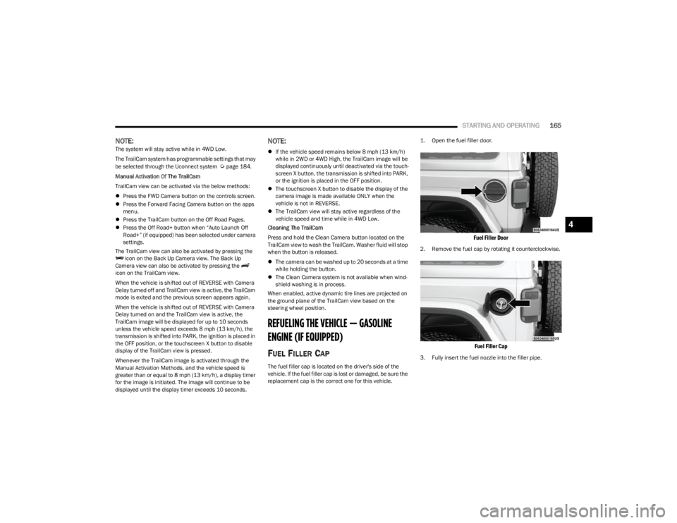
The fuel filler cap is located on the driver's side of the
vehicle. If the fuel filler cap is lost or damaged, be sure the
replacement cap is the correct one for this vehicle.
1. Open the fuel filler door.
Fuel Filler Door
2. Remove the fuel cap by rotating it counterclockwise.
Fuel Filler Cap
3. Fully insert the fuel nozzle into the filler pipe.
4
23_JL_OM_EN_USC_t.book Page 165
Page 170 of 396
168STARTING AND OPERATING
System Overview
This vehicle is equipped with a Diesel Exhaust Fluid (DEF)
injection system and a Selective Catalytic Reduction (SCR)
catalyst to meet the emission requirements.
The DEF injection system consists of the following
components:
DEF tank
DEF pump
DEF injector
Electronically-heated DEF Lines
NOx sensors
Temperature sensors
SCR catalyst
The DEF injection system and SCR catalyst enable the
achievement of diesel emission requirements; while
maintaining outstanding fuel economy, drivability, torque
and power ratings.
For system messages and warnings see
Úpage 108.
NOTE:
Your vehicle is equipped with a DEF injection system.
You may occasionally hear an audible clicking noise
from under the vehicle at a stop. This is normal opera -
tion.
The DEF pump will run for a period of time after engine
shutdown to purge the DEF system. This is normal
operation and may be audible from the rear of the
vehicle.
Diesel Exhaust Fluid Storage
Diesel Exhaust Fluid (DEF) is considered a very stable
product with a long shelf life. If DEF is kept in
temperatures between 10° and 90°F (-12° and 32°C), it
will last a minimum of one year.
DEF is subject to freezing at the lowest temperatures. For
example, DEF may freeze at temperatures at or below
12°F (-11°C). The system has been designed to operate
in this environment.
NOTE:When working with DEF, it is important to know that:
Any containers or parts that come into contact with DEF
must be DEF compatible (plastic or stainless steel).
Copper, brass, aluminum, iron or non-stainless steel
should be avoided as they are subject to corrosion by
DEF.
If DEF is spilled, it should be wiped up completely.
Adding Diesel Exhaust Fluid
The DEF gauge (located on the instrument cluster display)
will display the level of DEF remaining in the tank
Úpage 108.
NOTE:Driving conditions (altitude, vehicle speed, load, etc.) will
affect the amount of DEF that is used in your vehicle.
DEF FILL PROCEDURE
NOTE:
For the correct DEF fluid type see Úpage 374.
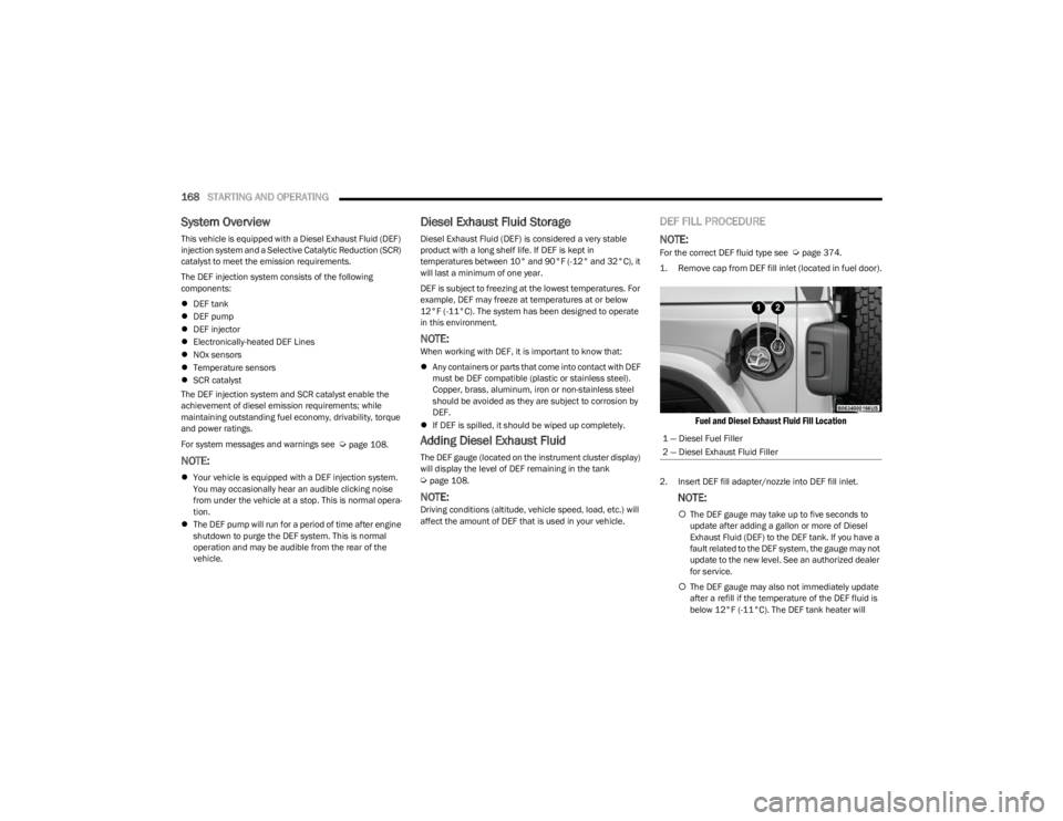
1. Remove cap from DEF fill inlet (located in fuel door).
Fuel and Diesel Exhaust Fluid Fill Location
2. Insert DEF fill adapter/nozzle into DEF fill inlet.
NOTE:
The DEF gauge may take up to five seconds to
update after adding a gallon or more of Diesel
Exhaust Fluid (DEF) to the DEF tank. If you have a
fault related to the DEF system, the gauge may not
update to the new level. See an authorized dealer
for service.
The DEF gauge may also not immediately update
after a refill if the temperature of the DEF fluid is
below 12°F (-11°C). The DEF tank heater will
1 — Diesel Fuel Filler
2 — Diesel Exhaust Fluid Filler
23_JL_OM_EN_USC_t.book Page 168
Page 171 of 396
STARTING AND OPERATING169
possibly warm up the DEF fluid and allow the
gauge to update after a period of run time. Under
very cold conditions, it is possible that the gauge
may not reflect the new fill level for several drives.
Excessive overfilling of the DEF tank can result in
a MIL lamp/fault code and inaccurate level read -
ings.
Refilling With Nozzles
You can fill up at any DEF distributor.
Proceed as follows:
Insert the DEF nozzle in the filler, start refilling and
stop refilling at the first shut-off (the shut-off indi -
cates that the DEF tank is full). Do not proceed
with the refilling, to prevent spillage of DEF.
Extract the nozzle.
Refilling With Containers
Proceed as follows:
Check the expiration date.
Read the advice for use on the label before
pouring the content of the bottle into the DEF tank.
If systems which cannot be screwed in (e.g. tanks)
are used for refilling, after the indication appears
on the instrument panel display
Úpage 104 fill
the DEF tank with no more than 2 gal (8 L).
If containers which can be screwed to the filler are
used, the reservoir is full when the DEF level in the
container stops pouring out. Do not proceed
further. 3. Stop filling the DEF tank immediately when any of the
following happen: DEF stops flowing from the fill
bottle into the DEF fill inlet, DEF splashes out the fill
inlet, or a DEF pump nozzle automatically shuts off.
4. Reinstall cap onto DEF fill inlet.
VEHICLE LOADING
CERTIFICATION LABEL
As required by National Highway Traffic Safety
Administration regulations, your vehicle has a certification
label affixed to the driver's side door or pillar.
This label contains the month and year of manufacture,
Gross Vehicle Weight Rating (GVWR), Gross Axle Weight
Rating (GAWR) front and rear, and Vehicle Identification
Number (VIN). A Month-Day-Hour (MDH) number is
included on this label and indicates the Month, Day and
Hour of manufacture. The bar code that appears on the
bottom of the label is your VIN.
Gross Vehicle Weight Rating (GVWR)
The GVWR is the total permissible weight of your vehicle
including driver, passengers, vehicle, options and cargo.
The label also specifies maximum capacities of front and
rear axle systems (GAWR). Total load must be limited so
GVWR and front and rear GAWR are not exceeded.
CAUTION!
To avoid DEF spillage, and possible damage to the
DEF tank from overfilling, do not “top off” the DEF
tank after filling.
DO NOT OVERFILL. DEF will freeze below 12ºF
(-11ºC). The DEF system is designed to work in
temperatures below the DEF freezing point, however,
if the tank is overfilled and freezes, the system could
be damaged.
When DEF is spilled, clean the area immediately with
water and use an absorbent material to soak up the
spills on the ground.
Do not attempt to start your engine if DEF is acciden -
tally added to the diesel fuel tank as it can result in
severe damage to your engine, including but not
limited to failure of the fuel pump and injectors.
Never add anything other than DEF to the tank –
especially any form of hydrocarbon such as diesel
fuel, fuel system additives, gasoline, or any other
petroleum-based product. Even a very small amount
of these, less than 100 parts per million or less than
1 oz. per 78 gal (295 L) will contaminate the entire
DEF system and will require replacement. If owners
use a container, funnel or nozzle when refilling the
tank, it should either be new or one that has only
been used for adding DEF. Mopar® provides an
attachable nozzle with its DEF for this purpose.
4
23_JL_OM_EN_USC_t.book Page 169
Page 176 of 396
174STARTING AND OPERATING
(Continued)
Towing Requirements — Tires
Proper tire inflation pressures are essential to the safe
and satisfactory operation of your vehicle.
Check the trailer tires for proper tire inflation pressures
before trailer usage.
Check for signs of tire wear or visible tire damage
before towing a trailer.
Replacing tires with a higher load carrying capacity will
not increase the vehicle's GVWR and GAWR limits.
For further information
Úpage 345.
Towing Requirements — Trailer Brakes
Do not interconnect the hydraulic brake system or
vacuum system of your vehicle with that of the trailer.
This could cause inadequate braking and possible
personal injury.
An electronically actuated trailer brake controller is
required when towing a trailer with electronically actu -
ated brakes. When towing a trailer equipped with a
hydraulic surge actuated brake system, an electronic
brake controller is not required.
Trailer brakes are recommended for trailers over 1,000
lb (453 kg) and required for trailers in excess of 2,000
lb (907 kg).
Towing Requirements — Trailer Lights And
Wiring
Whenever you pull a trailer, regardless of the trailer size,
stop lights and turn signals on the trailer are required for
motoring safety.
The Trailer Tow Package may include a four- and seven-pin
wiring harness. Use a factory approved trailer harness and
connector.
NOTE:Do not cut or splice wiring into the vehicle’s wiring
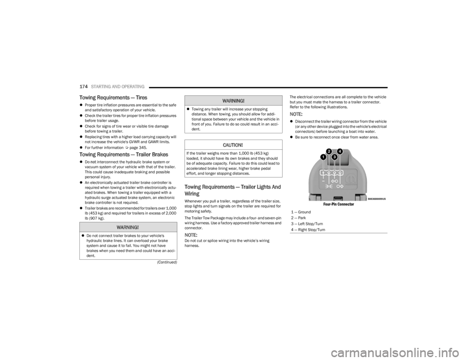
harness. The electrical connections are all complete to the vehicle
but you must mate the harness to a trailer connector.
Refer to the following illustrations.
NOTE:
Disconnect the trailer wiring connector from the vehicle
(or any other device plugged into the vehicle's electrical
connectors) before launching a boat into water.
Be sure to reconnect once clear from water area.
Four-Pin Connector
WARNING!
Do not connect trailer brakes to your vehicle's
hydraulic brake lines. It can overload your brake
system and cause it to fail. You might not have
brakes when you need them and could have an acci -
dent.
Towing any trailer will increase your stopping
distance. When towing, you should allow for addi -
tional space between your vehicle and the vehicle in
front of you. Failure to do so could result in an acci -
dent.
CAUTION!
If the trailer weighs more than 1,000 lb (453 kg)
loaded, it should have its own brakes and they should
be of adequate capacity. Failure to do this could lead to
accelerated brake lining wear, higher brake pedal
effort, and longer stopping distances.
WARNING!
1 — Ground
2 — Park
3 — Left Stop/Turn
4 — Right Stop/Turn
23_JL_OM_EN_USC_t.book Page 174