JEEP XJ 1995 Service And Repair Manual
Manufacturer: JEEP, Model Year: 1995, Model line: XJ, Model: JEEP XJ 1995Pages: 2158, PDF Size: 81.9 MB
Page 1281 of 2158
minutes). The use of a locating dowel is recom-
mended during assembly to prevent smearing the
material off location.
Mopar Gasket Maker should be applied sparingly
to one gasket surface. The sealant diameter should
be 1.00 mm (0.04 inch) or less. Be certain the mate-
rial surrounds each mounting hole. Excess material
can easily be wiped off. Components should be
torqued in place within 15 minutes. The use of a lo-
cating dowel is recommended during assembly to pre-
vent smearing the material off location.
ENGINE PERFORMANCE
To provide best vehicle performance and lowest ve-
hicle emissions, it is most important that the tune-up
be done accurately. Use the specifications listed on
the Vehicle Emission Control Information label found
on the engine compartment hood.
(1) Test battery specific gravity. Add water, if nec-
essary. Clean and tighten battery connections.
(2) Test cranking amperage draw (refer to Group
8B, Battery/Starter Service for the proper proce-
dures).
(3) Tighten the intake manifold bolts (refer to
Group 11, Exhaust System and Intake Manifold for
the proper specifications).
(4) Perform cylinder compression test:
(a) Check engine oil level and add oil, if neces-
sary.
(b) Drive the vehicle until engine reaches normal
operating temperature.
(c) Select a route free from traffic and other
forms of congestion, observe all traffic laws and
briskly accelerate through the gears several times.
The higher engine speed may help clean out valve
seat deposits which can prevent accurate compres-
sion readings.
CAUTION: DO NOT overspeed the engine.
(d) Remove all spark plugs from engine. As spark
plugs are being removed, check electrodes for ab-
normal firing indicatorsÐfouled, hot, oily, etc.
Record cylinder number of spark plug for future
reference.
(e) Disconnect coil wire from distributor and se-
cure to good ground to prevent a spark from start-
ing a fire.
(f) Be sure throttle blades are fully open during
the compression check.
(g) Insert compression gage adaptor into the
No.1 spark plug hole. Crank engine until maximum
pressure is reached on gauge. Record this pressure
as No.1 cylinder pressure.
(h) Repeat Step 4g for all remaining cylinders.
(i) Compression should not be less than 689 kPa
(100 psi) and not vary more than 172 kPa (25 psi)
from cylinder to cylinder.(j) If cylinder(s) have abnormally low compres-
sion pressures, repeat steps 4a through 4h.
(k) If the same cylinder(s) repeat an abnormally
low reading, it could indicate the existence of a
problem in the cylinder.
The recommended compression pressures are
to be used only as a guide to diagnosing engine
problems. An engine should NOT be disassem-
bled to determine the cause of low compression
unless some malfunction is present.
(5) Clean or replace spark plugs as necessary. Ad-
just gap (refer to Group 8D, Ignition System for gap
adjustment and torque).
(6) Test resistance of spark plug cables (refer to
Group 8D, Ignition System).
(7) Inspect the primary wire. Test coil output volt-
age, primary and secondary resistance. Replace parts
as necessary (refer to Group 8D, Ignition System and
make necessary adjustment).
(8) Perform a combustion analysis.
(9) Test fuel pump for pressure (refer to Group 14,
Fuel System for the proper specifications).
(10) Inspect air filter element (refer to Group 0,
Lubrication and Maintenance for the proper proce-
dure).
(11) Inspect crankcase ventilation system (refer to
Group 0, Lubrication and Maintenance for the proper
procedure).
(12) For emission controls refer to Group 25, Emis-
sion Controls System for service procedures.
(13) Inspect and adjust accessory belt drives (refer
to Group 7, Cooling System for the proper adjust-
ments).
(14) Road test vehicle as a final test.
HONING CYLINDER BORES
Before honing, stuff plenty of clean shop towels un-
der the bores and over the crankshaft to keep abra-
sive materials from entering the crankshaft area.
(1) Used carefully, the Cylinder Bore Sizing Hone
C-823 equipped with 220 grit stones, is the best tool
for this job. In addition to deglazing, it will reduce
taper and out-of-round as well as removing light
scuffing, scoring or scratches. Usually a few strokes
will clean up a bore and maintain the required lim-
its.
CAUTION: DO NOT use rigid type hones to remove
cylinder wall glaze.
(2) Deglazing of the cylinder walls may be done if
the cylinder bore is straight and round. Use a cylin-
der surfacing hone, Honing Tool C-3501, equipped
with 280 grit stones (C-3501-3810). 20-60 strokes, de-
pending on the bore condition, will be sufficient to
provide a satisfactory surface. Using honing oil
C-3501-3880 or a light honing oil available from ma-
jor oil distributors.
9 - 2 ENGINESJ
Page 1282 of 2158
CAUTION: DO NOT use engine or transmission oil,
mineral spirits or kerosene.
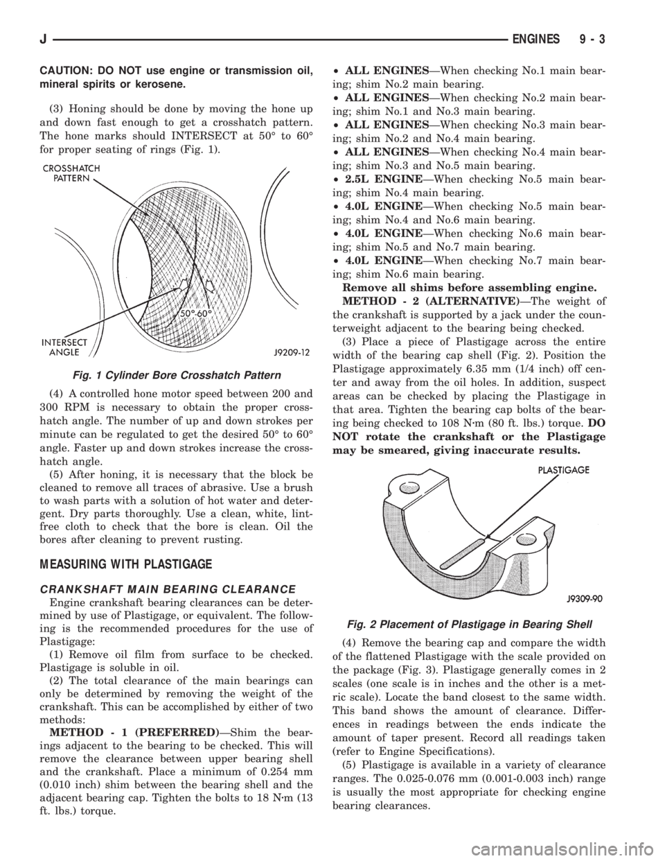
(3) Honing should be done by moving the hone up
and down fast enough to get a crosshatch pattern.
The hone marks should INTERSECT at 50É to 60É
for proper seating of rings (Fig. 1).
(4) A controlled hone motor speed between 200 and
300 RPM is necessary to obtain the proper cross-
hatch angle. The number of up and down strokes per
minute can be regulated to get the desired 50É to 60É
angle. Faster up and down strokes increase the cross-
hatch angle.
(5) After honing, it is necessary that the block be
cleaned to remove all traces of abrasive. Use a brush
to wash parts with a solution of hot water and deter-
gent. Dry parts thoroughly. Use a clean, white, lint-
free cloth to check that the bore is clean. Oil the
bores after cleaning to prevent rusting.
MEASURING WITH PLASTIGAGE
CRANKSHAFT MAIN BEARING CLEARANCE
Engine crankshaft bearing clearances can be deter-
mined by use of Plastigage, or equivalent. The follow-
ing is the recommended procedures for the use of
Plastigage:
(1) Remove oil film from surface to be checked.
Plastigage is soluble in oil.
(2) The total clearance of the main bearings can
only be determined by removing the weight of the
crankshaft. This can be accomplished by either of two
methods:
METHOD - 1 (PREFERRED)ÐShim the bear-
ings adjacent to the bearing to be checked. This will
remove the clearance between upper bearing shell
and the crankshaft. Place a minimum of 0.254 mm
(0.010 inch) shim between the bearing shell and the
adjacent bearing cap. Tighten the bolts to 18 Nzm (13
ft. lbs.) torque.²ALL ENGINESÐWhen checking No.1 main bear-
ing; shim No.2 main bearing.
²ALL ENGINESÐWhen checking No.2 main bear-
ing; shim No.1 and No.3 main bearing.
²ALL ENGINESÐWhen checking No.3 main bear-
ing; shim No.2 and No.4 main bearing.
²ALL ENGINESÐWhen checking No.4 main bear-
ing; shim No.3 and No.5 main bearing.
²2.5L ENGINEÐWhen checking No.5 main bear-
ing; shim No.4 main bearing.
²4.0L ENGINEÐWhen checking No.5 main bear-
ing; shim No.4 and No.6 main bearing.
²4.0L ENGINEÐWhen checking No.6 main bear-
ing; shim No.5 and No.7 main bearing.
²4.0L ENGINEÐWhen checking No.7 main bear-
ing; shim No.6 main bearing.
Remove all shims before assembling engine.
METHOD - 2 (ALTERNATIVE)ÐThe weight of
the crankshaft is supported by a jack under the coun-
terweight adjacent to the bearing being checked.
(3) Place a piece of Plastigage across the entire
width of the bearing cap shell (Fig. 2). Position the
Plastigage approximately 6.35 mm (1/4 inch) off cen-
ter and away from the oil holes. In addition, suspect
areas can be checked by placing the Plastigage in
that area. Tighten the bearing cap bolts of the bear-
ing being checked to 108 Nzm (80 ft. lbs.) torque.DO
NOT rotate the crankshaft or the Plastigage
may be smeared, giving inaccurate results.
(4) Remove the bearing cap and compare the width
of the flattened Plastigage with the scale provided on
the package (Fig. 3). Plastigage generally comes in 2
scales (one scale is in inches and the other is a met-
ric scale). Locate the band closest to the same width.
This band shows the amount of clearance. Differ-
ences in readings between the ends indicate the
amount of taper present. Record all readings taken
(refer to Engine Specifications).
(5) Plastigage is available in a variety of clearance
ranges. The 0.025-0.076 mm (0.001-0.003 inch) range
is usually the most appropriate for checking engine
bearing clearances.
Fig. 1 Cylinder Bore Crosshatch Pattern
Fig. 2 Placement of Plastigage in Bearing Shell
JENGINES 9 - 3
Page 1283 of 2158
CONNECTING ROD BEARING CLEARANCE
Engine connecting rod bearing clearances can be
determined by use of Plastigage, or equivalent. The
following is the recommended procedures for the use
of Plastigage:
(1) Remove oil film from surface to be checked.
Plastigage is soluble in oil.
(2) Place a piece of Plastigage across the entire width
of the bearing cap shell (Fig. 2). Position the Plastigage
approximately 6.35 mm (1/4 inch) off center and away
from the oil holes. In addition, suspect areas can be
checked by placing the Plastigage in the suspect area.
(3) The crankshaft must be turned until the connect-
ing rod to be checked starts moving toward the top of
the engine. Only then should the rod cap with Plasti-
gage in place be assembled. Tighten the rod cap nut to
45 Nzm (33 ft. lbs.) torque.DO NOT rotate the crank-
shaft or the Plastigage may be smeared, giving in-
accurate results.
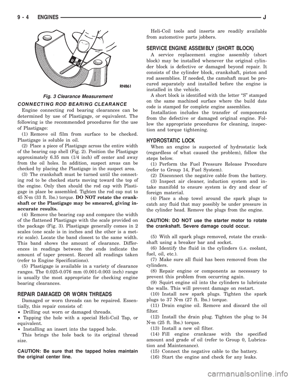
(4) Remove the bearing cap and compare the width
of the flattened Plastigage with the scale provided on
the package (Fig. 3). Plastigage generally comes in 2
scales (one scale is in inches and the other is a met-
ric scale). Locate the band closest to the same width.
This band shows the amount of clearance. Differ-
ences in readings between the ends indicate the
amount of taper present. Record all readings taken
(refer to Engine Specifications).
(5) Plastigage is available in a variety of clearance
ranges. The 0.025-0.076 mm (0.001-0.003 inch) range
is usually the most appropriate for checking engine
bearing clearances.
REPAIR DAMAGED OR WORN THREADS
Damaged or worn threads can be repaired. Essen-
tially, this repair consists of:
²Drilling out worn or damaged threads.
²Tapping the hole with a special Heli-Coil Tap, or
equivalent.
²Installing an insert into the tapped hole.
This brings the hole back to its original thread
size.
CAUTION: Be sure that the tapped holes maintain
the original center line.Heli-Coil tools and inserts are readily available
from automotive parts jobbers.
SERVICE ENGINE ASSEMBLY (SHORT BLOCK)
A service replacement engine assembly (short
block) may be installed whenever the original cylin-
der block is defective or damaged beyond repair. It
consists of the cylinder block, crankshaft, piston and
rod assemblies. If needed, the camshaft must be pro-
cured separately and installed before the engine is
installed in the vehicle.
A short block is identified with the letter ``S'' stamped
on the same machined surface where the build date
code is stamped for complete engine assemblies.
Installation includes the transfer of components
from the defective or damaged original engine. Fol-
low the appropriate procedures for cleaning, inspec-
tion and torque tightening.
HYDROSTATIC LOCK
When an engine is suspected of hydrostatic lock
(regardless of what caused the problem), follow the
steps below.
(1) Perform the Fuel Pressure Release Procedure
(refer to Group 14, Fuel System).
(2) Disconnect the negative cable from the battery.
(3) Inspect air cleaner, induction system and in-
take manifold to ensure system is dry and clear of
foreign material.
(4) Place a shop towel around the spark plugs to
catch any fluid that may possibly be under pressure in
the cylinder head. Remove the plugs from the engine.
CAUTION: DO NOT use the starter motor to rotate
the crankshaft. Severe damage could occur.
(5) With all spark plugs removed, rotate the crank-
shaft using a breaker bar and socket.
(6) Identify the fluid in the cylinders (i.e. coolant,
fuel, oil, etc.).
(7) Make sure all fluid has been removed from the
cylinders.
(8) Repair engine or components as necessary to
prevent this problem from occurring again.
(9) Squirt engine oil into the cylinders to lubricate
the walls. This will prevent damage on restart.
(10) Install new spark plugs. Tighten the spark
plugs to 37 Nzm (27 ft. lbs.) torque.
(11) Drain engine oil. Remove and discard the oil
filter.
(12) Install the drain plug. Tighten the plug to 34
Nzm (25 ft. lbs.) torque.
(13) Install a new oil filter.
(14) Fill engine crankcase with the specified
amount and grade of oil (refer to Group 0, Lubrica-
tion and Maintenance).
(15) Connect the negative cable to the battery.
(16) Start the engine and check for any leaks.
Fig. 3 Clearance Measurement
9 - 4 ENGINESJ
Page 1284 of 2158
ENGINE DIAGNOSIS
Engine diagnosis is helpful in determining the
causes of malfunctions not detected and remedied by
routine tune-ups.
These malfunctions may be classified as either per-
formance (e.g., engine idles rough and stalls) or me-
chanical (e.g., a strange noise).
Refer to the Service DiagnosisÐPerformance chart
and the Service DiagnosisÐMechanical chart for pos-
sible causes and corrections of malfunctions. Refer to
Group 14, Fuel System for the fuel system diagnosis.
GENERAL INFORMATION
Additional tests and diagnostic procedures may be
necessary for specific engine malfunctions that can
not be isolated with the Service Diagnosis charts. In-
formation concerning additional tests and diagnosis
is provided within the following diagnosis:
²Cylinder Compression Pressure Test.
²Cylinder Combustion Pressure Leakage Test.
²Engine Cylinder Head Gasket Failure Diagnosis.
²Intake Manifold Leakage Diagnosis.
INTAKE MANIFOLD LEAKAGE DIAGNOSIS
An intake manifold air leak is characterized by
lower than normal manifold vacuum. Also, one or
more cylinders may not be functioning.
WARNING: USE EXTREME CAUTION WHEN THE
ENGINE IS OPERATING. DO NOT STAND IN A DI-
RECT LINE WITH THE FAN. DO NOT PUT YOUR
HANDS NEAR THE PULLEYS, BELTS OR THE FAN.
DO NOT WEAR LOOSE CLOTHING.
METHOD 1
(1) Start the engine.
(2) Spray a small stream of water at the suspected
leak area.
(3) If a change in RPM'S, the area of the suspected
leak has been found.
(4) Repair as required.
CYLINDER COMPRESSION PRESSURE TEST
The results of a cylinder compression pressure test
can be utilized to diagnose several engine malfunc-
tions.
Ensure the battery is completely charged and the
engine starter motor is in good operating condition.
Otherwise the indicated compression pressures may
not be valid for diagnosis purposes.
(1) Clean the spark plug recesses with compressed
air.
(2) Remove the spark plugs.
(3) Secure the throttle in the wide-open position.
(4) Disconnect the ignition coil.(5) Insert a compression pressure gauge and rotate
the engine with the engine starter motor for three
revolutions.
(6) Record the compression pressure on the 3rd
revolution. Continue the test for the remaining cylin-
ders.
Refer to Engine Specifications for the correct en-
gine compression pressures.
ENGINE CYLINDER HEAD GASKET FAILURE
DIAGNOSIS
A leaking engine cylinder head gasket usually re-
sults in loss of power, loss of coolant and engine mis-
firing.
An engine cylinder head gasket leak can be located
between adjacent cylinders or between a cylinder and
the adjacent water jacket.
²An engine cylinder head gasket leaking between
adjacent cylinders is indicated by a loss of power
and/or engine misfire.
²An engine cylinder head gasket leaking between a
cylinder and an adjacent water jacket is indicated by
coolant foaming or overheating and loss of coolant.
CYLINDER-TO-CYLINDER LEAKAGE TEST
To determine if an engine cylinder head gasket is
leaking between adjacent cylinders; follow the proce-
dures outlined in Cylinder Compression Pressure
Test. An engine cylinder head gasket leaking between
adjacent cylinders will result in approximately a 50-
70% reduction in compression pressure.
CYLINDER-TO-WATER JACKET LEAKAGE
TEST
WARNING: USE EXTREME CAUTION WHEN THE
ENGINE IS OPERATING. DO NOT STAND IN A DI-
RECT LINE WITH THE FAN. DO NOT PUT YOUR
HANDS NEAR THE PULLEYS, BELTS OR THE FAN.
DO NOT WEAR LOOSE CLOTHING.
Remove the radiator cap.
Start the engine and allow it to warm up until the
engine thermostat opens.
If a large combustion/compression pressure leak ex-
ists, bubbles will be visible in the coolant.
If bubbles are not visible, install a radiator pres-
sure tester and pressurize the coolant system.
If a cylinder is leaking combustion pressure into
the water jacket, the tester pointer will pulsate with
every combustion stroke of the cylinder.
JENGINES 9 - 5
Page 1285 of 2158
CYLINDER COMBUSTION PRESSURE LEAKAGE
TEST
The combustion pressure leakage test provides an
accurate means for determining engine condition.
Combustion pressure leakage testing will detect:
²Exhaust and intake valve leaks (improper seat-
ing).
²Leaks between adjacent cylinders or into water
jacket.
²Any causes for combustion/compression pressure
loss.
WARNING: DO NOT REMOVE THE RADIATOR CAP
WITH THE SYSTEM HOT AND UNDER PRESSURE
BECAUSE SERIOUS BURNS FROM COOLANT CAN
OCCUR.
Check the coolant level and fill as required. DO
NOT install the radiator cap.
Start and operate the engine until it attains nor-
mal operating temperature, then turn the engine
OFF.
Remove the spark plugs.
Remove the oil filler cap.
Remove the air cleaner.
Calibrate the tester according to the manufactur-
er's instructions. The shop air source for testing
should maintain 483 kPa (70 psi) minimum, 1 379
kPa (200 psi) maximum and 552 kPa (80 psi) recom-
mended.
Perform the test procedures on each cylinder ac-
cording to the tester manufacturer's instructions.
While testing, listen for pressurized air escaping
through the throttle body, tailpipe and oil filler cap
opening. Check for bubbles in the radiator coolant.
All gauge pressure indications should be equal,
with no more than 25% leakage.
FOR EXAMPLE:At 552 kPa (80 psi) input pres-
sure, a minimum of 414 kPa (60 psi) should be main-
tained in the cylinder.
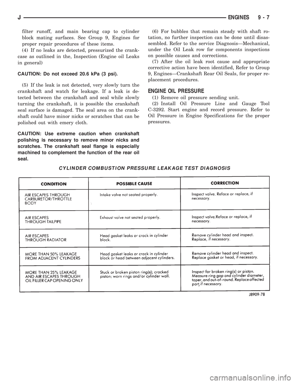
Refer to the Cylinder Combustion Pressure Leak-
age Test Diagnosis chart.
INSPECTION (ENGINE OIL LEAKS IN GENERAL)
Begin with a through visual inspection of the en-
gine, particularly at the area of the suspected leak. If
an oil leak source is not readily identifiable, the fol-
lowing steps should be followed:
(1) Do not clean or degrease the engine at this
time because some solvents may cause rubber to
swell, temporarily stopping the leak.
(2) Add an oil soluble dye (use as recommended by
manufacturer). Start the engine and let idle for ap-
proximately 15 minutes. Check the oil dipstick to
make sure the dye is thoroughly mixed as indicated
with a bright yellow color under a black light.(3) Using a black light, inspect the entire engine
for fluorescent dye, particularly at the suspected area
of oil leak. If the oil leak is found and identified, re-
pair per service manual instructions.
(4) If dye is not observed, drive the vehicle at var-
ious speeds for approximately 24km (15 miles), and
repeat step (3).
If the oil leak source is not positively identi-
fied at this time, proceed with the air leak detec-
tion test method as follows:
(1) Disconnect the breather cap to air cleaner hose
at the breather cap end. Cap or plug breather cap
nipple.
(2) Remove the PCV valve from the cylinder head
cover. Cap or plug the PCV valve grommet.
(3) Attach an air hose with pressure gauge and
regulator to the dipstick tube.
CAUTION: Do not subject the engine assembly to
more than 20.6 kpa (3 PSI) of test pressure.
(4) Gradually apply air pressure from 1 psi to 2.5
psi maximum while applying soapy water at the sus-
pected source. Adjust the regulator to the suitable
test pressure that provide the best bubbles which
will pinpoint the leak source. If the oil leak is de-
tected and identified, repair per service manual pro-
cedures.
(5) If the leakage occurs at the rear oil seal area,
refer to the section, Inspection for Rear Seal Area
Leak.
(6) If no leaks are detected, turn off the air supply
and remove the air hose and all plugs and caps. In-
stall the PCV valve and breather cap hose. Proceed
to step 7.
(7) Clean the oil off the suspect oil leak area using
a suitable solvent. Drive the vehicle at various
speeds approximately 24 km (15 miles). Inspect the
engine for signs of an oil leak by using a black light.
INSPECTION FOR REAR SEAL AREA LEAKS
Since it is sometimes difficult to determine the
source of an oil leak in the rear seal area of the en-
gine, a more involved inspection is necessary. The fol-
lowing steps should be followed to help pinpoint the
source of the leak.
If the leakage occurs at the crankshaft rear oil seal
area:
(1) Disconnect the battery.
(2) Raise the vehicle.
(3) Remove torque converter or clutch housing
cover and inspect rear of block for evidence of oil.
Use a black light to check for the oil leak:
(a) Circular spray pattern generally indicates
seal leakage or crankshaft damage.
(b) Where leakage tends to run straight down,
possible causes are a porous block, distributor seal,
camshaft bore cup plugs oil galley pipe plugs, oil
9 - 6 ENGINESJ
Page 1286 of 2158
filter runoff, and main bearing cap to cylinder
block mating surfaces. See Group 9, Engines for
proper repair procedures of these items.
(4) If no leaks are detected, pressurized the crank-
case as outlined in the, Inspection (Engine oil Leaks
in general)
CAUTION: Do not exceed 20.6 kPa (3 psi).
(5) If the leak is not detected, very slowly turn the
crankshaft and watch for leakage. If a leak is de-
tected between the crankshaft and seal while slowly
turning the crankshaft, it is possible the crankshaft
seal surface is damaged. The seal area on the crank-
shaft could have minor nicks or scratches that can be
polished out with emery cloth.
CAUTION: Use extreme caution when crankshaft
polishing is necessary to remove minor nicks and
scratches. The crankshaft seal flange is especially
machined to complement the function of the rear oil
seal.(6) For bubbles that remain steady with shaft ro-
tation, no further inspection can be done until disas-
sembled. Refer to the service DiagnosisÐMechanical,
under the Oil Leak row for components inspections
on possible causes and corrections.
(7) After the oil leak root cause and appropriate
corrective action have been identified, Refer to Group
9, EnginesÐCrankshaft Rear Oil Seals, for proper re-
placement procedures.
ENGINE OIL PRESSURE
(1) Remove oil pressure sending unit.
(2) Install Oil Pressure Line and Gauge Tool
C-3292. Start engine and record pressure. Refer to
Oil Pressure in Engine Specifications for the proper
pressures.
CYLINDER COMBUSTION PRESSURE LEAKAGE TEST DIAGNOSIS
JENGINES 9 - 7
Page 1287 of 2158
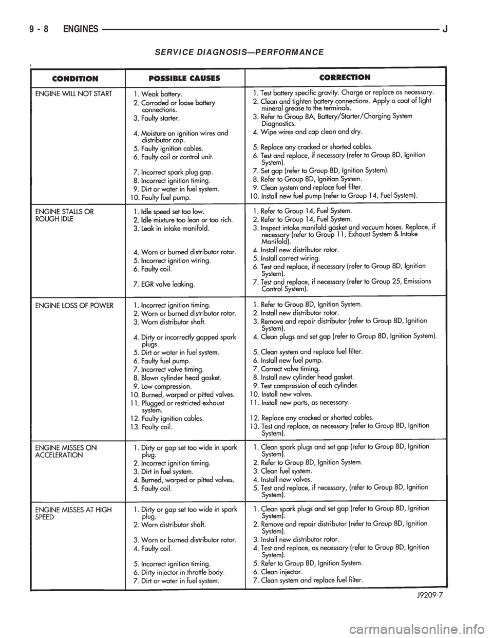
SERVICE DIAGNOSISÐPERFORMANCE
9 - 8 ENGINESJ
Page 1288 of 2158
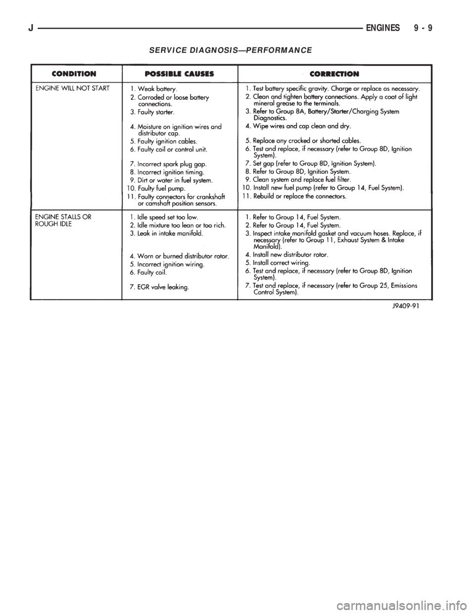
SERVICE DIAGNOSISÐPERFORMANCE
JENGINES 9 - 9
Page 1289 of 2158
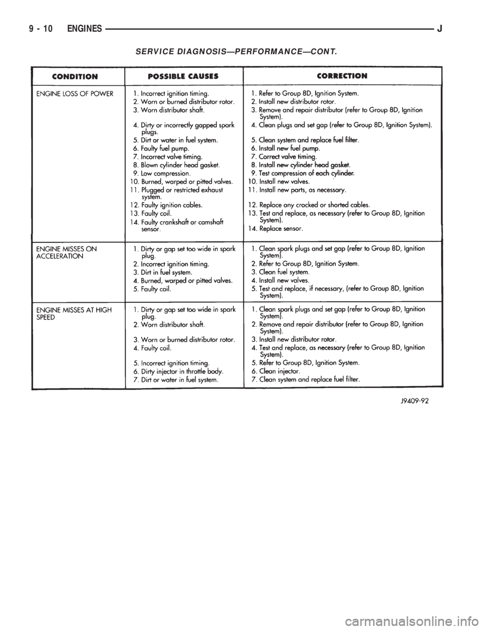
SERVICE DIAGNOSISÐPERFORMANCEÐCONT.
9 - 10 ENGINESJ
Page 1290 of 2158
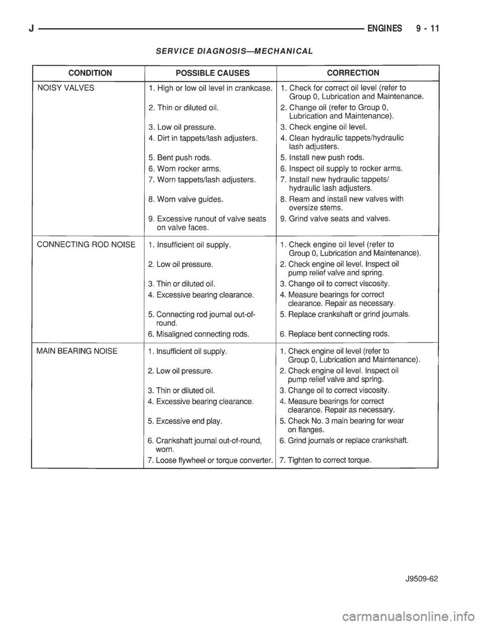
SERVICE DIAGNOSISÐMECHANICAL
JENGINES 9 - 11