JEEP XJ 1995 Service And Repair Manual
Manufacturer: JEEP, Model Year: 1995,
Model line: XJ,
Model: JEEP XJ 1995
Pages: 2158, PDF Size: 81.9 MB
JEEP XJ 1995 Service And Repair Manual
XJ 1995
JEEP
JEEP
https://www.carmanualsonline.info/img/16/57043/w960_57043-0.png
JEEP XJ 1995 Service And Repair Manual
Trending: wheel, lug pattern, air conditioning, automatic transmission, starting circuit, interior lights, maintenance
Page 1951 of 2158
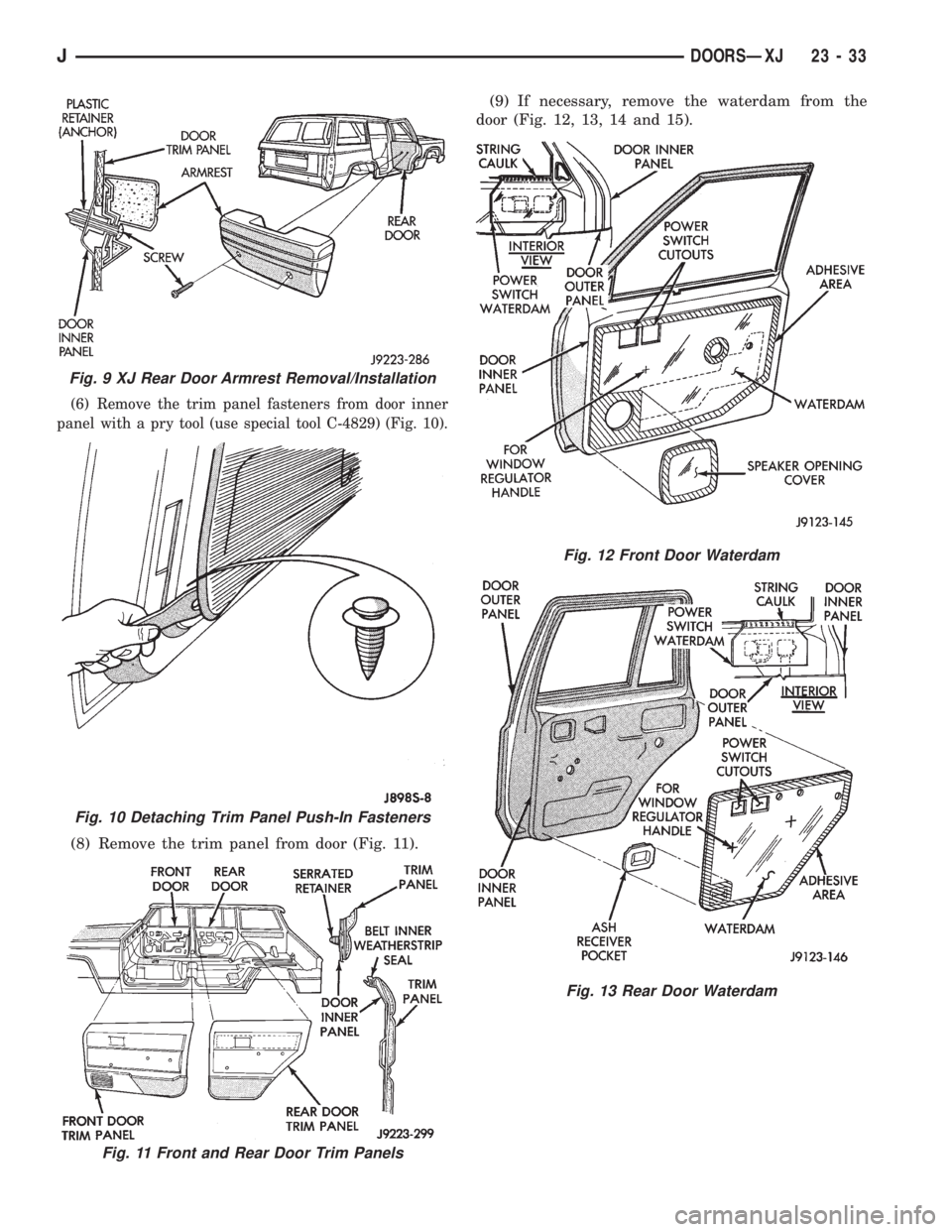
(6) Remove the trim panel fasteners from door inner
panel with a pry tool (use special tool C-4829) (Fig. 10).
(8) Remove the trim panel from door (Fig. 11).(9) If necessary, remove the waterdam from the
door (Fig. 12, 13, 14 and 15).
Fig. 9 XJ Rear Door Armrest Removal/Installation
Fig. 10 Detaching Trim Panel Push-In Fasteners
Fig. 11 Front and Rear Door Trim Panels
Fig. 12 Front Door Waterdam
Fig. 13 Rear Door Waterdam
JDOORSÐXJ 23 - 33
Page 1952 of 2158
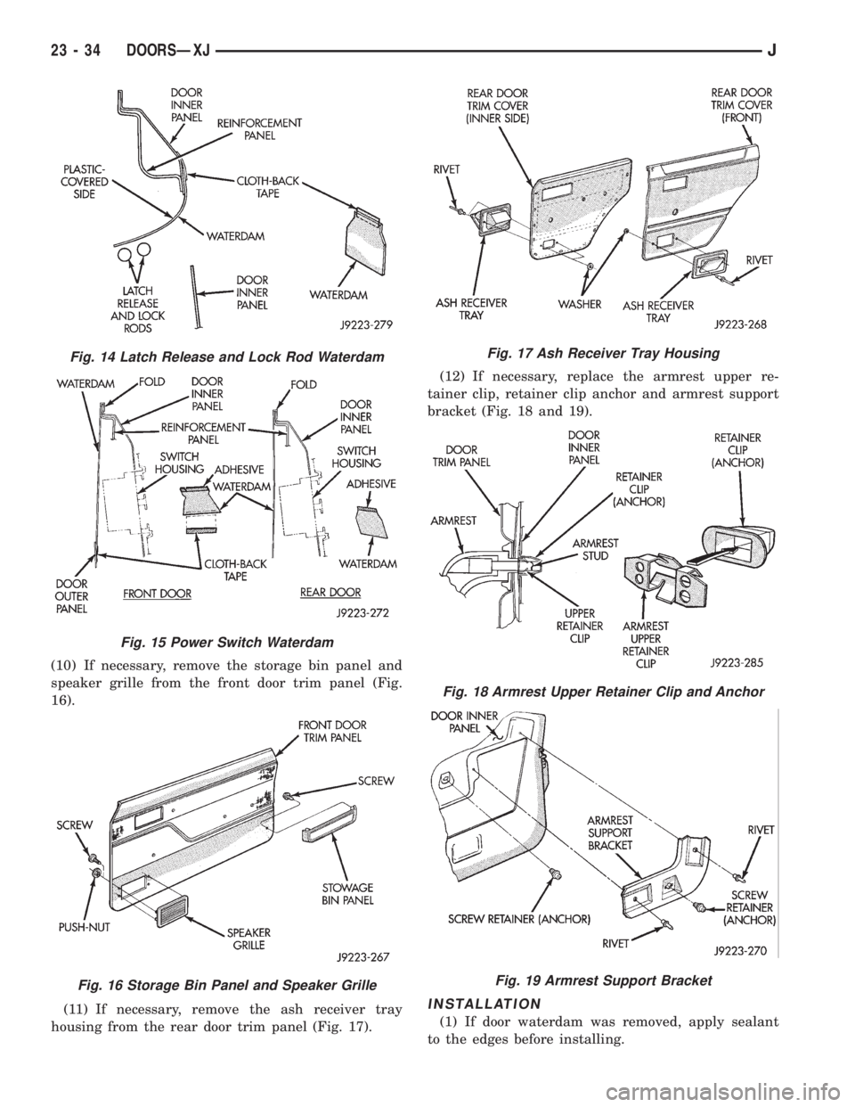
(10) If necessary, remove the storage bin panel and
speaker grille from the front door trim panel (Fig.
16).
(11) If necessary, remove the ash receiver tray
housing from the rear door trim panel (Fig. 17).(12) If necessary, replace the armrest upper re-
tainer clip, retainer clip anchor and armrest support
bracket (Fig. 18 and 19).
INSTALLATION
(1) If door waterdam was removed, apply sealant
to the edges before installing.
Fig. 14 Latch Release and Lock Rod Waterdam
Fig. 15 Power Switch Waterdam
Fig. 16 Storage Bin Panel and Speaker Grille
Fig. 17 Ash Receiver Tray Housing
Fig. 18 Armrest Upper Retainer Clip and Anchor
Fig. 19 Armrest Support Bracket
23 - 34 DOORSÐXJJ
Page 1953 of 2158
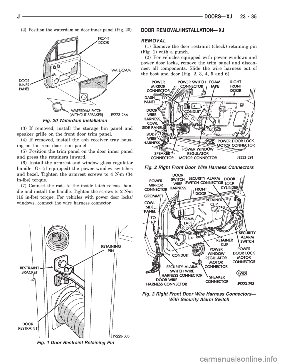
(2) Position the waterdam on door inner panel (Fig. 20).
(3) If removed, install the storage bin panel and
speaker grille on the front door trim panel.
(4) If removed, install the ash receiver tray hous-
ing on the rear door trim panel.
(5) Position the trim panel on the door inner panel
and press the retainers inward.
(6) Install the armrest and window glass regulator
handle. Or (if equipped) the power window switches
and bezel. Tighten the armrest screws to 4 Nzm (34
in-lbs) torque.
(7) Connect the rods to the inside latch release han-
dle and install the handle. Tighten the screws to 2 Nzm
(16 in-lbs) torque. For vehicles with power door locks/
windows, connect the wire harness connector.
DOOR REMOVAL/INSTALLATIONÐXJ
REMOVAL
(1) Remove the door restraint (check) retaining pin
(Fig. 1) with a punch.
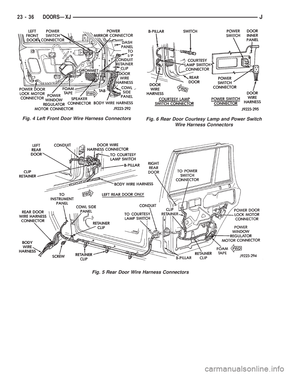
(2) For vehicles equipped with power windows and
power door locks, remove the trim panel and discon-
nect all components. Slide the wire harness out of
the boot and door (Fig. 2, 3, 4, 5 and 6)
Fig. 1 Door Restraint Retaining Pin
Fig. 20 Waterdam Installation
Fig. 2 Right Front Door Wire Harness Connectors
Fig. 3 Right Front Door Wire Harness ConnectorsÐ
With Security Alarm Switch
JDOORSÐXJ 23 - 35
Page 1954 of 2158
Fig. 4 Left Front Door Wire Harness Connectors
Fig. 5 Rear Door Wire Harness Connectors
Fig. 6 Rear Door Courtesy Lamp and Power Switch
Wire Harness Connectors
23 - 36 DOORSÐXJJ
Page 1955 of 2158
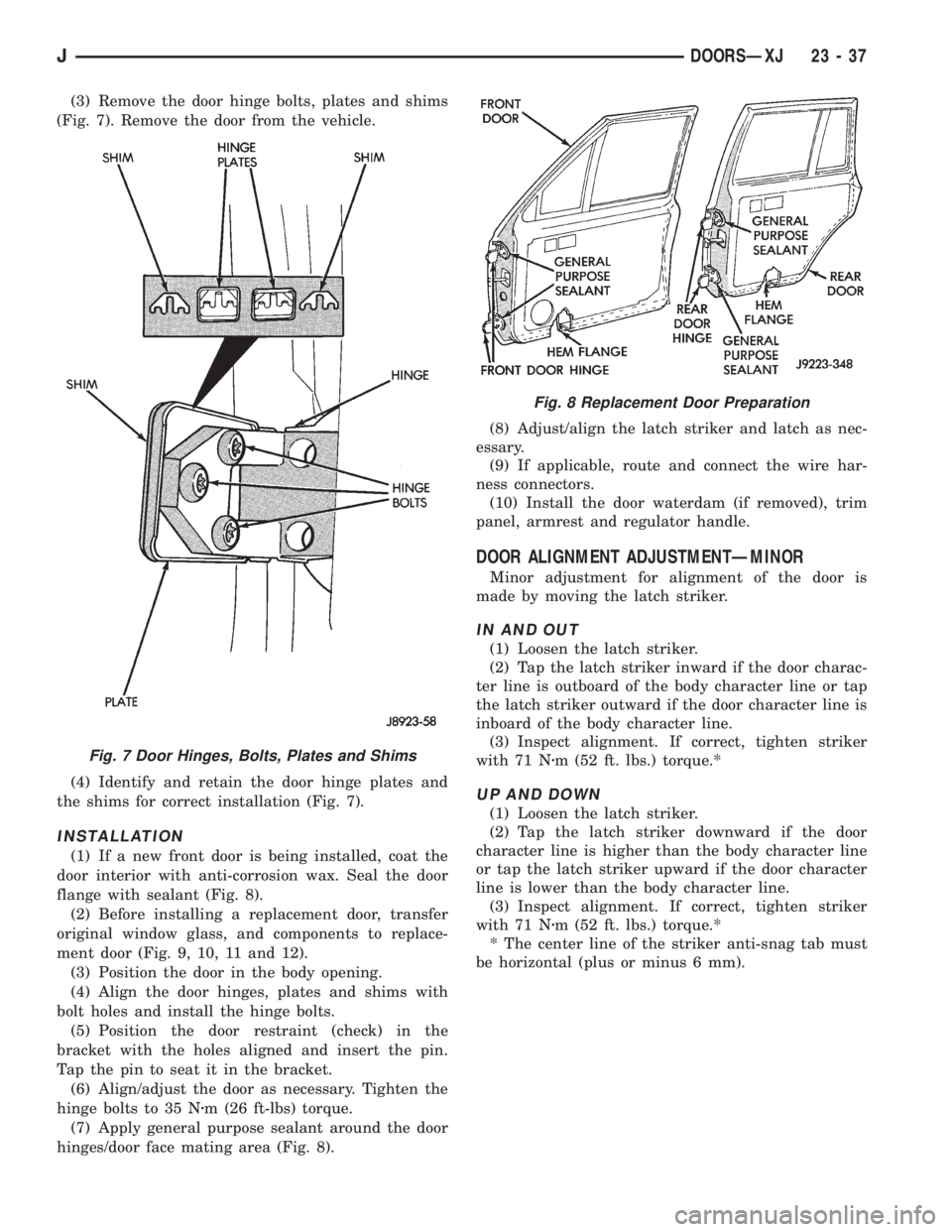
(3) Remove the door hinge bolts, plates and shims
(Fig. 7). Remove the door from the vehicle.
(4) Identify and retain the door hinge plates and
the shims for correct installation (Fig. 7).
INSTALLATION
(1) If a new front door is being installed, coat the
door interior with anti-corrosion wax. Seal the door
flange with sealant (Fig. 8).
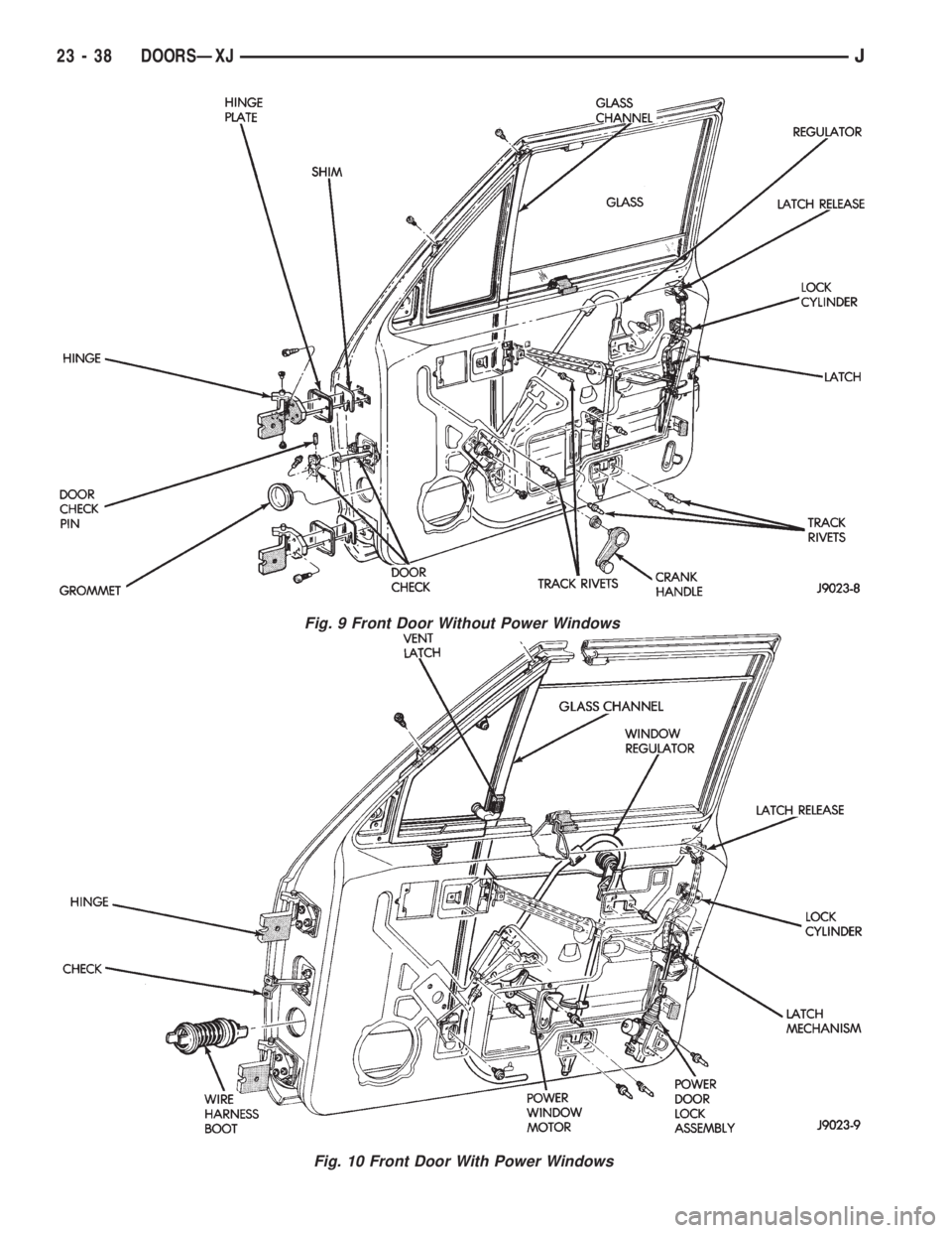
(2) Before installing a replacement door, transfer
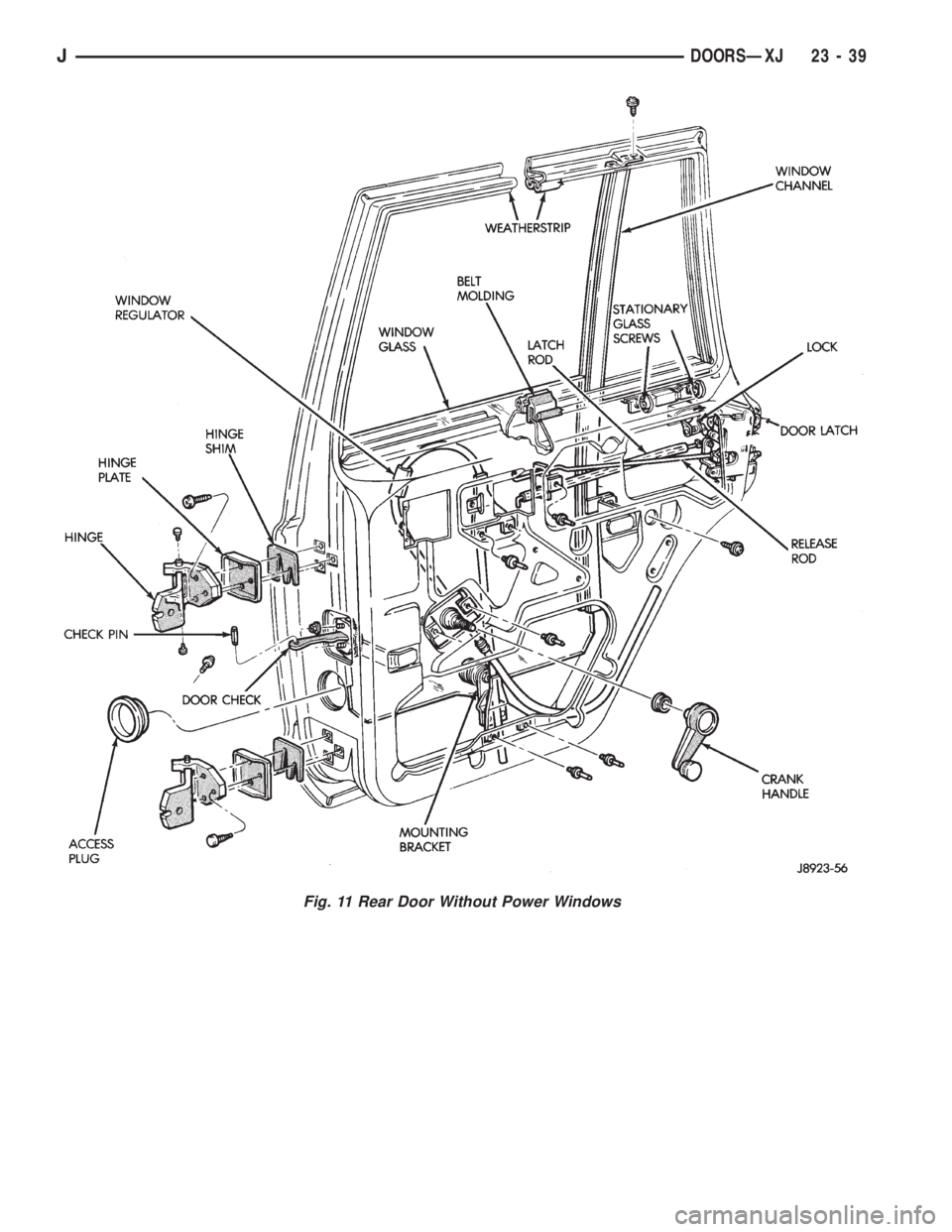
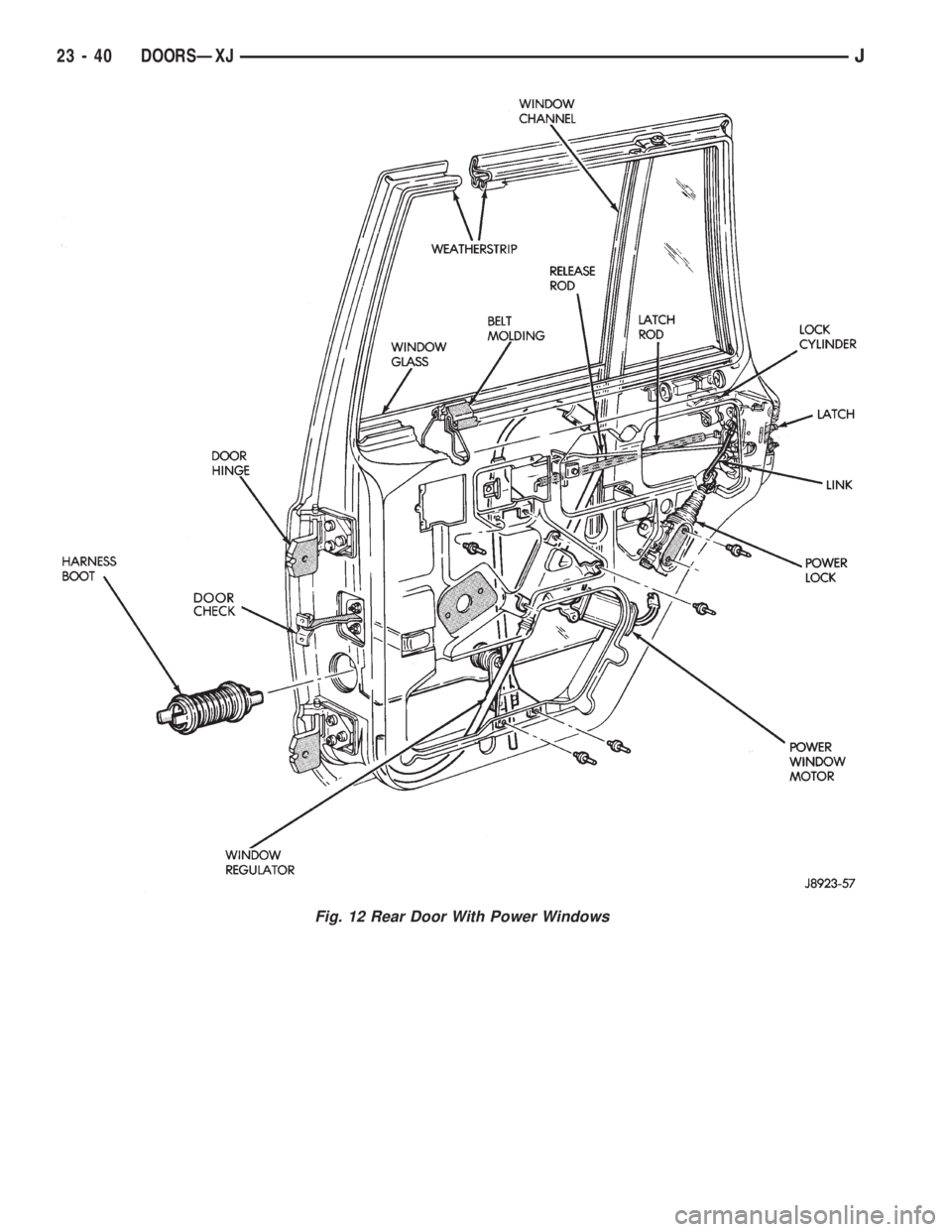
original window glass, and components to replace-
ment door (Fig. 9, 10, 11 and 12).
(3) Position the door in the body opening.
(4) Align the door hinges, plates and shims with
bolt holes and install the hinge bolts.
(5) Position the door restraint (check) in the
bracket with the holes aligned and insert the pin.
Tap the pin to seat it in the bracket.
(6) Align/adjust the door as necessary. Tighten the
hinge bolts to 35 Nzm (26 ft-lbs) torque.
(7) Apply general purpose sealant around the door
hinges/door face mating area (Fig. 8).(8) Adjust/align the latch striker and latch as nec-
essary.
(9) If applicable, route and connect the wire har-
ness connectors.
(10) Install the door waterdam (if removed), trim
panel, armrest and regulator handle.
DOOR ALIGNMENT ADJUSTMENTÐMINOR
Minor adjustment for alignment of the door is
made by moving the latch striker.
IN AND OUT
(1) Loosen the latch striker.
(2) Tap the latch striker inward if the door charac-
ter line is outboard of the body character line or tap
the latch striker outward if the door character line is
inboard of the body character line.
(3) Inspect alignment. If correct, tighten striker
with 71 Nzm (52 ft. lbs.) torque.*
UP AND DOWN
(1) Loosen the latch striker.
(2) Tap the latch striker downward if the door
character line is higher than the body character line
or tap the latch striker upward if the door character
line is lower than the body character line.
(3) Inspect alignment. If correct, tighten striker
with 71 Nzm (52 ft. lbs.) torque.*
* The center line of the striker anti-snag tab must
be horizontal (plus or minus 6 mm).
Fig. 7 Door Hinges, Bolts, Plates and Shims
Fig. 8 Replacement Door Preparation
JDOORSÐXJ 23 - 37
Page 1956 of 2158
Fig. 9 Front Door Without Power Windows
Fig. 10 Front Door With Power Windows
23 - 38 DOORSÐXJJ
Page 1957 of 2158
Fig. 11 Rear Door Without Power Windows
JDOORSÐXJ 23 - 39
Page 1958 of 2158
Fig. 12 Rear Door With Power Windows
23 - 40 DOORSÐXJJ
Page 1959 of 2158
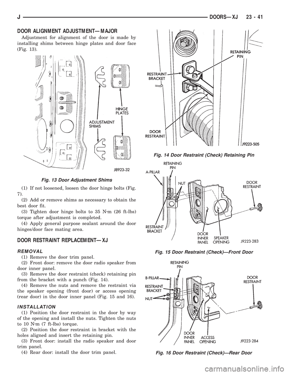
DOOR ALIGNMENT ADJUSTMENTÐMAJOR
Adjustment for alignment of the door is made by
installing shims between hinge plates and door face
(Fig. 13).
(1) If not loosened, loosen the door hinge bolts (Fig.
7).
(2) Add or remove shims as necessary to obtain the
best door fit.
(3) Tighten door hinge bolts to 35 Nzm (26 ft-lbs)
torque after adjustment is completed.
(4) Apply general purpose sealant around the door
hinges/door face mating area.
DOOR RESTRAINT REPLACEMENTÐXJ
REMOVAL
(1) Remove the door trim panel.
(2) Front door: remove the door radio speaker from
door inner panel.
(3) Remove the door restraint (check) retaining pin
from the bracket with a punch (Fig. 14).
(4) Remove the nuts and remove the restraint via
the speaker opening (front door) or access opening
(rear door) in the door inner panel (Fig. 15 and 16).
INSTALLATION
(1) Position the door restraint in the door by way
of the opening and install the nuts. Tighten the nuts
to 10 Nzm (7 ft-lbs) torque.
(2) Position the door restraint in bracket with the
holes aligned and insert the retaining pin.
(3) Front door: install the radio speaker and door
trim panel.
(4) Rear door: install the door trim panel.
Fig. 14 Door Restraint (Check) Retaining Pin
Fig. 15 Door Restraint (Check)ÐFront Door
Fig. 16 Door Restraint (Check)ÐRear Door
Fig. 13 Door Adjustment Shims
JDOORSÐXJ 23 - 41
Page 1960 of 2158
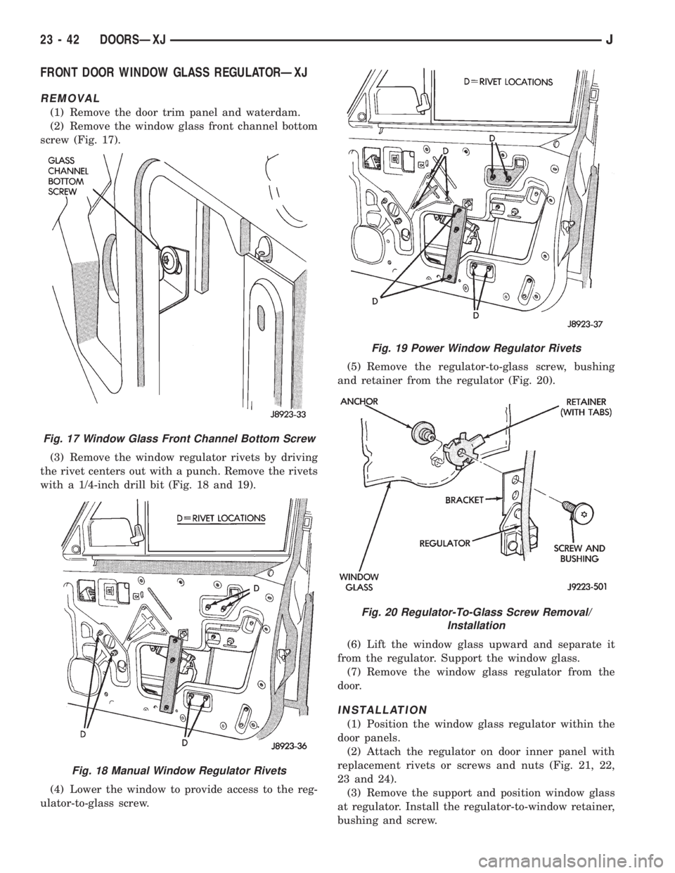
FRONT DOOR WINDOW GLASS REGULATORÐXJ
REMOVAL
(1) Remove the door trim panel and waterdam.
(2) Remove the window glass front channel bottom
screw (Fig. 17).
(3) Remove the window regulator rivets by driving
the rivet centers out with a punch. Remove the rivets
with a 1/4-inch drill bit (Fig. 18 and 19).
(4) Lower the window to provide access to the reg-
ulator-to-glass screw.(5) Remove the regulator-to-glass screw, bushing
and retainer from the regulator (Fig. 20).
(6) Lift the window glass upward and separate it
from the regulator. Support the window glass.
(7) Remove the window glass regulator from the
door.
INSTALLATION
(1) Position the window glass regulator within the
door panels.
(2) Attach the regulator on door inner panel with
replacement rivets or screws and nuts (Fig. 21, 22,
23 and 24).
(3) Remove the support and position window glass
at regulator. Install the regulator-to-window retainer,
bushing and screw.
Fig. 17 Window Glass Front Channel Bottom Screw
Fig. 18 Manual Window Regulator Rivets
Fig. 19 Power Window Regulator Rivets
Fig. 20 Regulator-To-Glass Screw Removal/
Installation
23 - 42 DOORSÐXJJ
Trending: driver seat adjustment, AUX, clock reset, oil change, battery, gas tank size, catalytic converter
