JEEP XJ 1995 Service And Repair Manual
Manufacturer: JEEP, Model Year: 1995, Model line: XJ, Model: JEEP XJ 1995Pages: 2158, PDF Size: 81.9 MB
Page 1961 of 2158
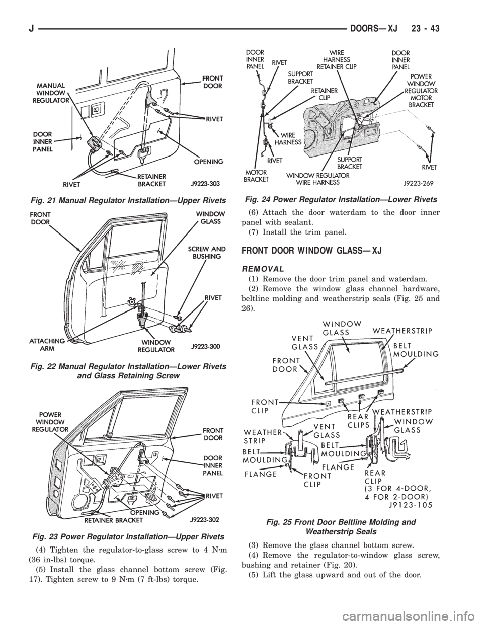
(4) Tighten the regulator-to-glass screw to 4 Nzm
(36 in-lbs) torque.
(5) Install the glass channel bottom screw (Fig.
17). Tighten screw to 9 Nzm (7 ft-lbs) torque.(6) Attach the door waterdam to the door inner
panel with sealant.
(7) Install the trim panel.
FRONT DOOR WINDOW GLASSÐXJ
REMOVAL
(1) Remove the door trim panel and waterdam.
(2) Remove the window glass channel hardware,
beltline molding and weatherstrip seals (Fig. 25 and
26).
(3) Remove the glass channel bottom screw.
(4) Remove the regulator-to-window glass screw,
bushing and retainer (Fig. 20).
(5) Lift the glass upward and out of the door.
Fig. 21 Manual Regulator InstallationÐUpper Rivets
Fig. 22 Manual Regulator InstallationÐLower Rivets
and Glass Retaining Screw
Fig. 23 Power Regulator InstallationÐUpper Rivets
Fig. 24 Power Regulator InstallationÐLower Rivets
Fig. 25 Front Door Beltline Molding and
Weatherstrip Seals
JDOORSÐXJ 23 - 43
Page 1962 of 2158
INSTALLATION
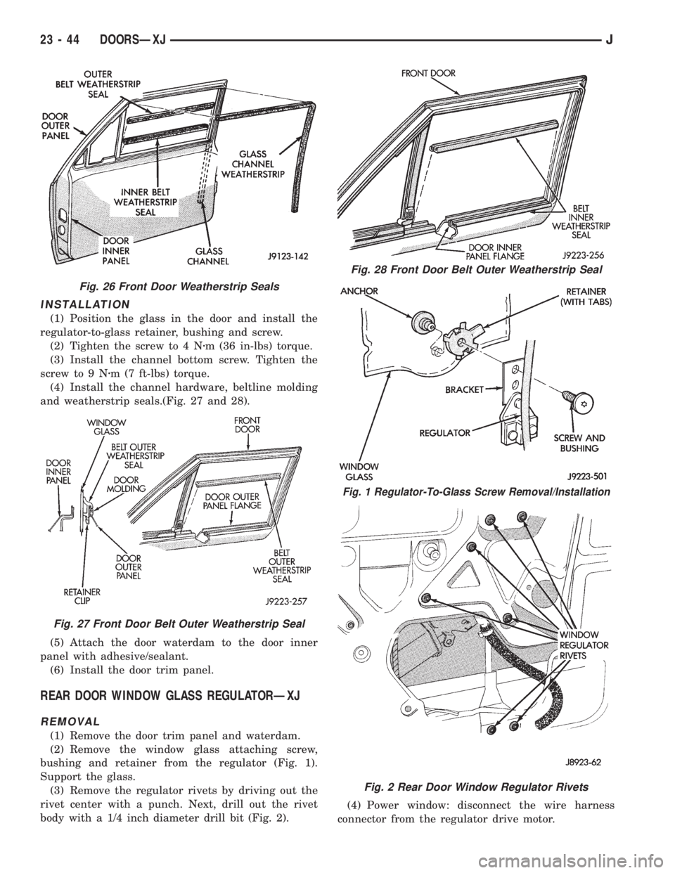
(1) Position the glass in the door and install the
regulator-to-glass retainer, bushing and screw.
(2) Tighten the screw to 4 Nzm (36 in-lbs) torque.
(3) Install the channel bottom screw. Tighten the
screw to 9 Nzm (7 ft-lbs) torque.
(4) Install the channel hardware, beltline molding
and weatherstrip seals.(Fig. 27 and 28).
(5) Attach the door waterdam to the door inner
panel with adhesive/sealant.
(6) Install the door trim panel.
REAR DOOR WINDOW GLASS REGULATORÐXJ
REMOVAL
(1) Remove the door trim panel and waterdam.
(2) Remove the window glass attaching screw,
bushing and retainer from the regulator (Fig. 1).
Support the glass.
(3) Remove the regulator rivets by driving out the
rivet center with a punch. Next, drill out the rivet
body with a 1/4 inch diameter drill bit (Fig. 2).(4) Power window: disconnect the wire harness
connector from the regulator drive motor.
Fig. 26 Front Door Weatherstrip Seals
Fig. 27 Front Door Belt Outer Weatherstrip Seal
Fig. 28 Front Door Belt Outer Weatherstrip Seal
Fig. 1 Regulator-To-Glass Screw Removal/Installation
Fig. 2 Rear Door Window Regulator Rivets
23 - 44 DOORSÐXJJ
Page 1963 of 2158
(5) Remove the regulator and drive motor, if
equipped.
INSTALLATION
(1) Position window regulator and, if equipped,
drive motor within the door panels.
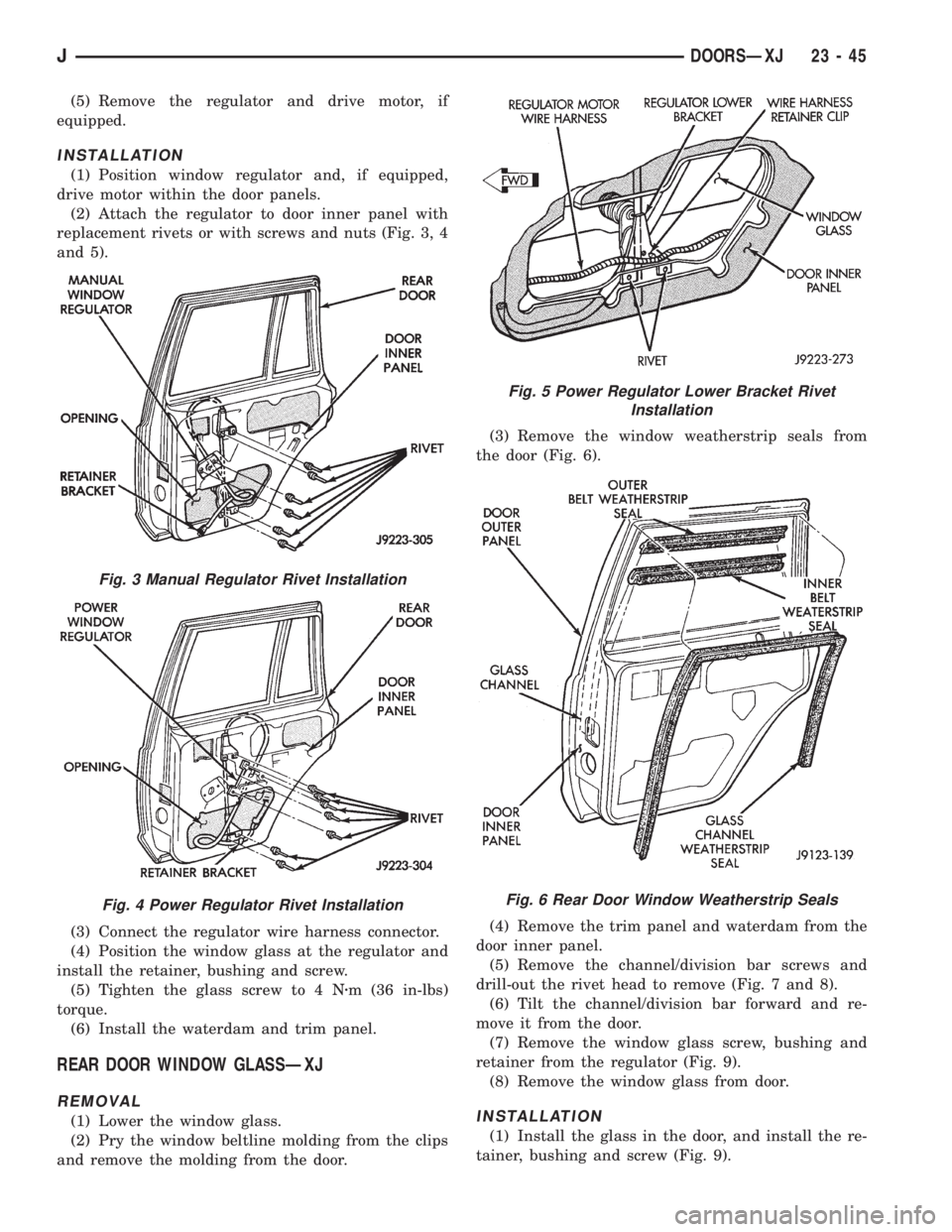
(2) Attach the regulator to door inner panel with
replacement rivets or with screws and nuts (Fig. 3, 4
and 5).
(3) Connect the regulator wire harness connector.
(4) Position the window glass at the regulator and
install the retainer, bushing and screw.
(5) Tighten the glass screw to 4 Nzm (36 in-lbs)
torque.
(6) Install the waterdam and trim panel.
REAR DOOR WINDOW GLASSÐXJ
REMOVAL
(1) Lower the window glass.
(2) Pry the window beltline molding from the clips
and remove the molding from the door.(3) Remove the window weatherstrip seals from
the door (Fig. 6).
(4) Remove the trim panel and waterdam from the
door inner panel.
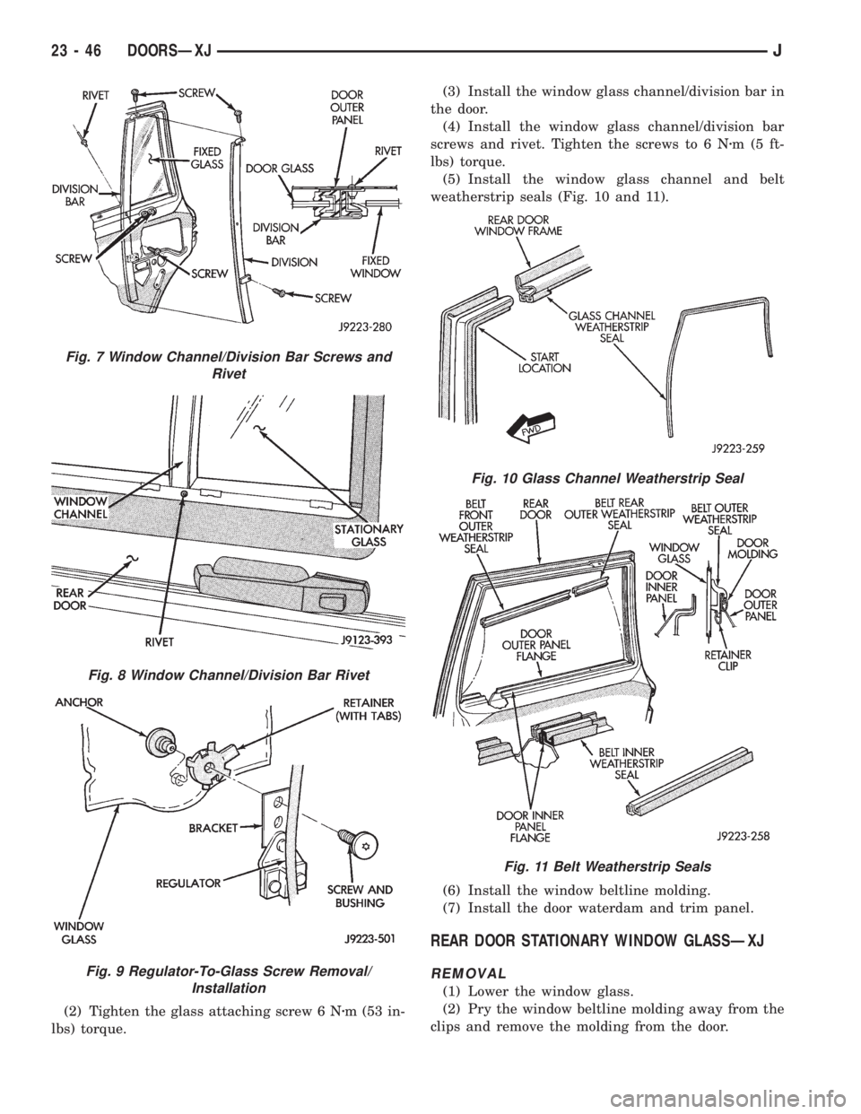
(5) Remove the channel/division bar screws and
drill-out the rivet head to remove (Fig. 7 and 8).
(6) Tilt the channel/division bar forward and re-
move it from the door.
(7) Remove the window glass screw, bushing and
retainer from the regulator (Fig. 9).
(8) Remove the window glass from door.INSTALLATION
(1) Install the glass in the door, and install the re-
tainer, bushing and screw (Fig. 9).
Fig. 3 Manual Regulator Rivet Installation
Fig. 4 Power Regulator Rivet Installation
Fig. 5 Power Regulator Lower Bracket Rivet
Installation
Fig. 6 Rear Door Window Weatherstrip Seals
JDOORSÐXJ 23 - 45
Page 1964 of 2158
(2) Tighten the glass attaching screw 6 Nzm (53 in-
lbs) torque.(3) Install the window glass channel/division bar in
the door.
(4) Install the window glass channel/division bar
screws and rivet. Tighten the screws to 6 Nzm(5ft-
lbs) torque.
(5) Install the window glass channel and belt
weatherstrip seals (Fig. 10 and 11).
(6) Install the window beltline molding.
(7) Install the door waterdam and trim panel.
REAR DOOR STATIONARY WINDOW GLASSÐXJ
REMOVAL
(1) Lower the window glass.
(2) Pry the window beltline molding away from the
clips and remove the molding from the door.
Fig. 7 Window Channel/Division Bar Screws and
Rivet
Fig. 8 Window Channel/Division Bar Rivet
Fig. 9 Regulator-To-Glass Screw Removal/
Installation
Fig. 10 Glass Channel Weatherstrip Seal
Fig. 11 Belt Weatherstrip Seals
23 - 46 DOORSÐXJJ
Page 1965 of 2158
(3) Remove the window weatherstrip seals from
the door.
(4) Remove the trim panel and waterdam from
door inner panel.
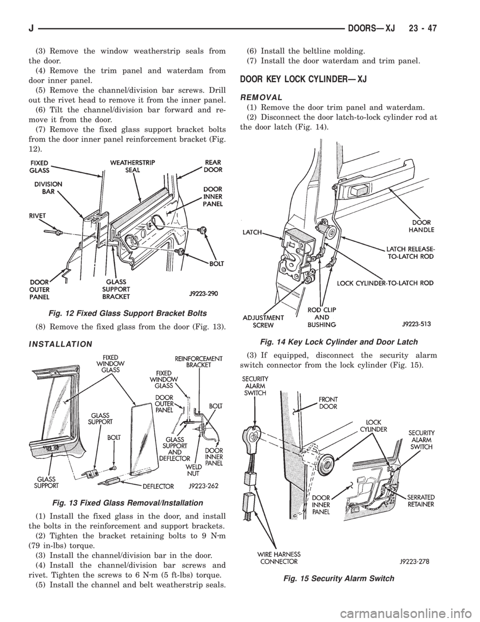
(5) Remove the channel/division bar screws. Drill
out the rivet head to remove it from the inner panel.
(6) Tilt the channel/division bar forward and re-
move it from the door.
(7) Remove the fixed glass support bracket bolts
from the door inner panel reinforcement bracket (Fig.
12).
(8) Remove the fixed glass from the door (Fig. 13).
INSTALLATION
(1) Install the fixed glass in the door, and install
the bolts in the reinforcement and support brackets.
(2) Tighten the bracket retaining bolts to 9 Nzm
(79 in-lbs) torque.
(3) Install the channel/division bar in the door.
(4) Install the channel/division bar screws and
rivet. Tighten the screws to 6 Nzm (5 ft-lbs) torque.
(5) Install the channel and belt weatherstrip seals.(6) Install the beltline molding.
(7) Install the door waterdam and trim panel.
DOOR KEY LOCK CYLINDERÐXJ
REMOVAL
(1) Remove the door trim panel and waterdam.
(2) Disconnect the door latch-to-lock cylinder rod at
the door latch (Fig. 14).
(3) If equipped, disconnect the security alarm
switch connector from the lock cylinder (Fig. 15).
Fig. 12 Fixed Glass Support Bracket Bolts
Fig. 13 Fixed Glass Removal/Installation
Fig. 14 Key Lock Cylinder and Door Latch
Fig. 15 Security Alarm Switch
JDOORSÐXJ 23 - 47
Page 1966 of 2158
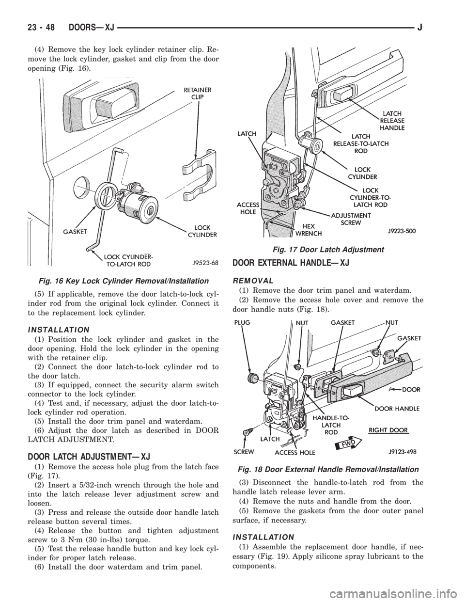
(4) Remove the key lock cylinder retainer clip. Re-
move the lock cylinder, gasket and clip from the door
opening (Fig. 16).
(5) If applicable, remove the door latch-to-lock cyl-
inder rod from the original lock cylinder. Connect it
to the replacement lock cylinder.
INSTALLATION
(1) Position the lock cylinder and gasket in the
door opening. Hold the lock cylinder in the opening
with the retainer clip.
(2) Connect the door latch-to-lock cylinder rod to
the door latch.
(3) If equipped, connect the security alarm switch
connector to the lock cylinder.
(4) Test and, if necessary, adjust the door latch-to-
lock cylinder rod operation.
(5) Install the door trim panel and waterdam.
(6) Adjust the door latch as described in DOOR
LATCH ADJUSTMENT.
DOOR LATCH ADJUSTMENTÐXJ
(1) Remove the access hole plug from the latch face
(Fig. 17).
(2) Insert a 5/32-inch wrench through the hole and
into the latch release lever adjustment screw and
loosen.
(3) Press and release the outside door handle latch
release button several times.
(4) Release the button and tighten adjustment
screw to 3 Nzm (30 in-lbs) torque.
(5) Test the release handle button and key lock cyl-
inder for proper latch release.
(6) Install the door waterdam and trim panel.
DOOR EXTERNAL HANDLEÐXJ
REMOVAL
(1) Remove the door trim panel and waterdam.
(2) Remove the access hole cover and remove the
door handle nuts (Fig. 18).
(3) Disconnect the handle-to-latch rod from the
handle latch release lever arm.
(4) Remove the nuts and handle from the door.
(5) Remove the gaskets from the door outer panel
surface, if necessary.
INSTALLATION
(1) Assemble the replacement door handle, if nec-
essary (Fig. 19). Apply silicone spray lubricant to the
components.
Fig. 16 Key Lock Cylinder Removal/Installation
Fig. 17 Door Latch Adjustment
Fig. 18 Door External Handle Removal/Installation
23 - 48 DOORSÐXJJ
Page 1967 of 2158
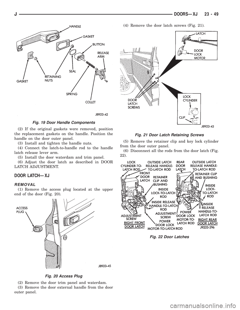
(2) If the original gaskets were removed, position
the replacement gaskets on the handle. Position the
handle on the door outer panel.
(3) Install and tighten the handle nuts.
(4) Connect the latch-to-handle rod to the handle
latch release lever arm.
(5) Install the door waterdam and trim panel.
(6) Adjust the door latch as described in DOOR
LATCH ADJUSTMENT.
DOOR LATCHÐXJ
REMOVAL
(1) Remove the access plug located at the upper
end of the door (Fig. 20).
(2) Remove the door trim panel and waterdam.
(3) Remove the door external handle from the door
outer panel.(4) Remove the door latch screws (Fig. 21).
(5) Remove the retainer clip and key lock cylinder
from the door outer panel.
(6) Disconnect all the rods from the door latch (Fig.
22).
Fig. 19 Door Handle Components
Fig. 20 Access Plug
Fig. 21 Door Latch Retaining Screws
Fig. 22 Door Latches
JDOORSÐXJ 23 - 49
Page 1968 of 2158
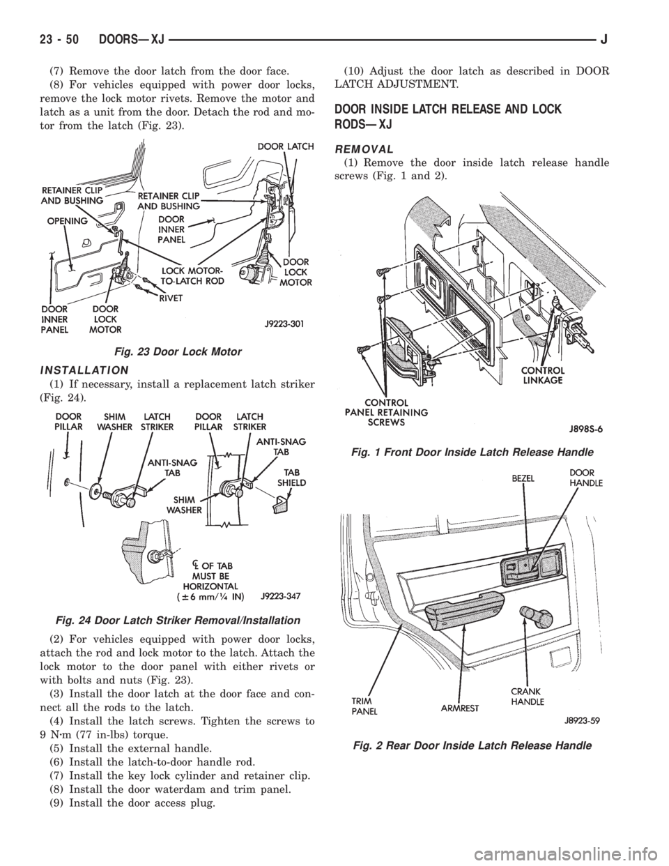
(7) Remove the door latch from the door face.
(8) For vehicles equipped with power door locks,
remove the lock motor rivets. Remove the motor and
latch as a unit from the door. Detach the rod and mo-
tor from the latch (Fig. 23).
INSTALLATION
(1) If necessary, install a replacement latch striker
(Fig. 24).
(2) For vehicles equipped with power door locks,
attach the rod and lock motor to the latch. Attach the
lock motor to the door panel with either rivets or
with bolts and nuts (Fig. 23).
(3) Install the door latch at the door face and con-
nect all the rods to the latch.
(4) Install the latch screws. Tighten the screws to
9Nzm (77 in-lbs) torque.
(5) Install the external handle.
(6) Install the latch-to-door handle rod.
(7) Install the key lock cylinder and retainer clip.
(8) Install the door waterdam and trim panel.
(9) Install the door access plug.(10) Adjust the door latch as described in DOOR
LATCH ADJUSTMENT.
DOOR INSIDE LATCH RELEASE AND LOCK
RODSÐXJ
REMOVAL
(1) Remove the door inside latch release handle
screws (Fig. 1 and 2).
Fig. 23 Door Lock Motor
Fig. 24 Door Latch Striker Removal/Installation
Fig. 1 Front Door Inside Latch Release Handle
Fig. 2 Rear Door Inside Latch Release Handle
23 - 50 DOORSÐXJJ
Page 1969 of 2158
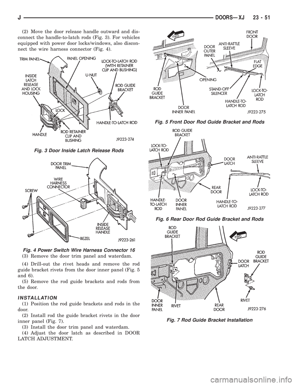
(2) Move the door release handle outward and dis-
connect the handle-to-latch rods (Fig. 3). For vehicles
equipped with power door locks/windows, also discon-
nect the wire harness connector (Fig. 4).
(4) Drill-out the rivet heads and remove the rod
guide bracket rivets from the door inner panel (Fig. 5
and 6).
(5) Remove the rod guide brackets and rods from
the door.
INSTALLATION
(1) Position the rod guide brackets and rods in the
door.
(2) Install rod the guide bracket rivets in the door
inner panel (Fig. 7).
(3) Install the door trim panel and waterdam.
(4) Adjust the door latch as described in DOOR
LATCH ADJUSTMENT.
Fig. 3 Door Inside Latch Release Rods
Fig. 4 Power Switch Wire Harness Connector 16
(3) Remove the door trim panel and waterdam.
Fig. 5 Front Door Rod Guide Bracket and Rods
Fig. 6 Rear Door Rod Guide Bracket and Rods
Fig. 7 Rod Guide Bracket Installation
JDOORSÐXJ 23 - 51
Page 1970 of 2158
DOOR HINGE/HINGE PIN REPLACEMENTÐXJ
REMOVAL
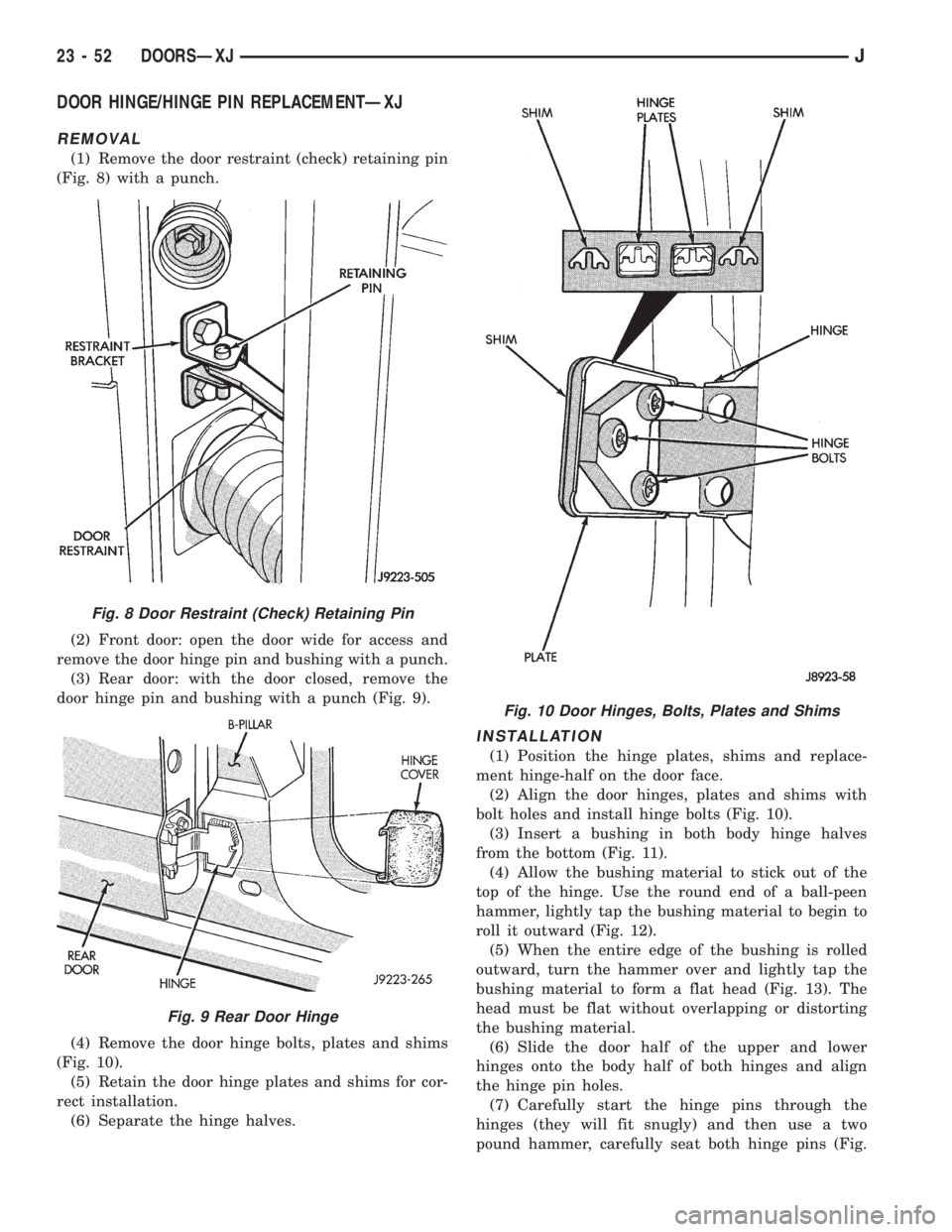
(1) Remove the door restraint (check) retaining pin
(Fig. 8) with a punch.
(2) Front door: open the door wide for access and
remove the door hinge pin and bushing with a punch.
(3) Rear door: with the door closed, remove the
door hinge pin and bushing with a punch (Fig. 9).
(4) Remove the door hinge bolts, plates and shims
(Fig. 10).
(5) Retain the door hinge plates and shims for cor-
rect installation.
(6) Separate the hinge halves.
INSTALLATION
(1) Position the hinge plates, shims and replace-
ment hinge-half on the door face.
(2) Align the door hinges, plates and shims with
bolt holes and install hinge bolts (Fig. 10).
(3) Insert a bushing in both body hinge halves
from the bottom (Fig. 11).
(4) Allow the bushing material to stick out of the
top of the hinge. Use the round end of a ball-peen
hammer, lightly tap the bushing material to begin to
roll it outward (Fig. 12).
(5) When the entire edge of the bushing is rolled
outward, turn the hammer over and lightly tap the
bushing material to form a flat head (Fig. 13). The
head must be flat without overlapping or distorting
the bushing material.
(6) Slide the door half of the upper and lower
hinges onto the body half of both hinges and align
the hinge pin holes.
(7) Carefully start the hinge pins through the
hinges (they will fit snugly) and then use a two
pound hammer, carefully seat both hinge pins (Fig.
Fig. 8 Door Restraint (Check) Retaining Pin
Fig. 9 Rear Door Hinge
Fig. 10 Door Hinges, Bolts, Plates and Shims
23 - 52 DOORSÐXJJ