sensor JEEP YJ 1995 Service And Owner's Guide
[x] Cancel search | Manufacturer: JEEP, Model Year: 1995, Model line: YJ, Model: JEEP YJ 1995Pages: 2158, PDF Size: 81.9 MB
Page 331 of 2158
(8) If voltage is not present at supply wire, check
for voltage at pin-7 of powertrain control module
(PCM) 60-way connector. Leave the PCM connector
connected for this test.
(9) If voltage is still not present, perform vehicle
test using the DRB scan tool.
(10) If voltage is present at pin-7, but not at the
supply wire:
(a) Check continuity between the supply wire.
This is checked between the distributor connector
and pin-7 at the PCM. If continuity is not present,
repair the harness as necessary.
(b) Check for continuity between the camshaft
position sensor output wire and pin-44 at the PCM.
If continuity is not present, repair the harness as
necessary.
(c) Check for continuity between the ground cir-
cuit wire at the distributor connector and ground.
If continuity is not present, repair the harness as
necessary.
(11) While observing the voltmeter, crank the en-
gine with ignition switch. The voltmeter needle
should fluctuate between 0 and 5 volts while the en-
gine is cranking. This verifies that the camshaft po-
sition sensor in the distributor is operating properly
and a sync pulse signal is being generated.
If sync pulse signal is not present, replacement of
the camshaft position sensor is necessary.
For removal or installation of ignition system com-
ponents, refer to the Component Removal/Installa-
tion section of this group.
For system operation and component identification,
refer to the Component Identification/System Opera-
tion section of this group.
CRANKSHAFT POSITION SENSOR TEST
To perform a complete test of this sensor and its
circuitry, refer to the DRB scan tool. Also refer to the
appropriate Powertrain Diagnostics Procedures man-
ual. To test the sensor only, refer to the following:
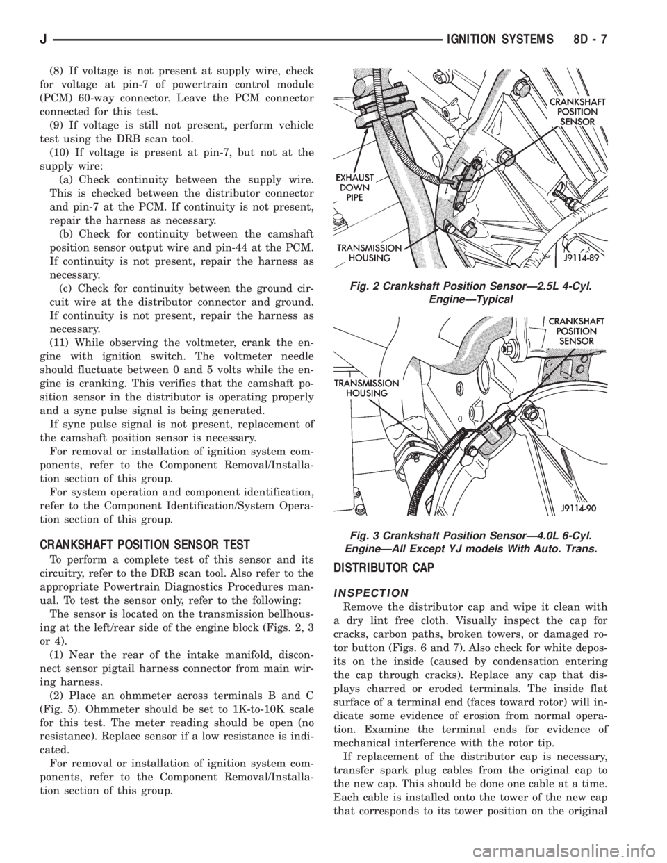
The sensor is located on the transmission bellhous-
ing at the left/rear side of the engine block (Figs. 2, 3
or 4).
(1) Near the rear of the intake manifold, discon-
nect sensor pigtail harness connector from main wir-
ing harness.
(2) Place an ohmmeter across terminals B and C
(Fig. 5). Ohmmeter should be set to 1K-to-10K scale
for this test. The meter reading should be open (no
resistance). Replace sensor if a low resistance is indi-
cated.
For removal or installation of ignition system com-
ponents, refer to the Component Removal/Installa-
tion section of this group.DISTRIBUTOR CAP
INSPECTION
Remove the distributor cap and wipe it clean with
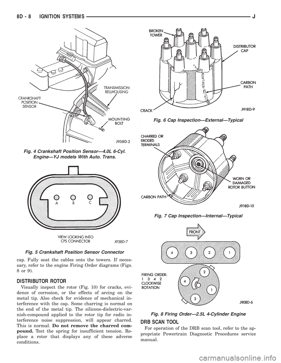
a dry lint free cloth. Visually inspect the cap for
cracks, carbon paths, broken towers, or damaged ro-
tor button (Figs. 6 and 7). Also check for white depos-
its on the inside (caused by condensation entering
the cap through cracks). Replace any cap that dis-
plays charred or eroded terminals. The inside flat
surface of a terminal end (faces toward rotor) will in-
dicate some evidence of erosion from normal opera-
tion. Examine the terminal ends for evidence of
mechanical interference with the rotor tip.
If replacement of the distributor cap is necessary,
transfer spark plug cables from the original cap to
the new cap. This should be done one cable at a time.
Each cable is installed onto the tower of the new cap
that corresponds to its tower position on the original
Fig. 2 Crankshaft Position SensorÐ2.5L 4-Cyl.
EngineÐTypical
Fig. 3 Crankshaft Position SensorÐ4.0L 6-Cyl.
EngineÐAll Except YJ models With Auto. Trans.
JIGNITION SYSTEMS 8D - 7
Page 332 of 2158
cap. Fully seat the cables onto the towers. If neces-
sary, refer to the engine Firing Order diagrams (Figs.
8or9).
DISTRIBUTOR ROTOR
Visually inspect the rotor (Fig. 10) for cracks, evi-
dence of corrosion, or the effects of arcing on the
metal tip. Also check for evidence of mechanical in-
terference with the cap. Some charring is normal on
the end of the metal tip. The silicone-dielectric-var-
nish-compound applied to the rotor tip for radio in-
terference noise suppression, will appear charred.
This is normal.Do not remove the charred com-
pound.Test the spring for insufficient tension. Re-
place a rotor that displays any of these adverse
conditions.
DRB SCAN TOOL
For operation of the DRB scan tool, refer to the ap-
propriate Powertrain Diagnostic Procedures service
manual.
Fig. 4 Crankshaft Position SensorÐ4.0L 6-Cyl.
EngineÐYJ models With Auto. Trans.
Fig. 5 Crankshaft Position Sensor Connector
Fig. 6 Cap InspectionÐExternalÐTypical
Fig. 7 Cap InspectionÐInternalÐTypical
Fig. 8 Firing OrderÐ2.5L 4-Cylinder Engine
8D - 8 IGNITION SYSTEMSJ
Page 333 of 2158
IGNITION COIL
To perform a complete test of the ignition coil and
its circuitry, refer to the DRB scan tool. Also refer tothe appropriate Powertrain Diagnostics Procedures
manual. To test the coil only, refer to the following:
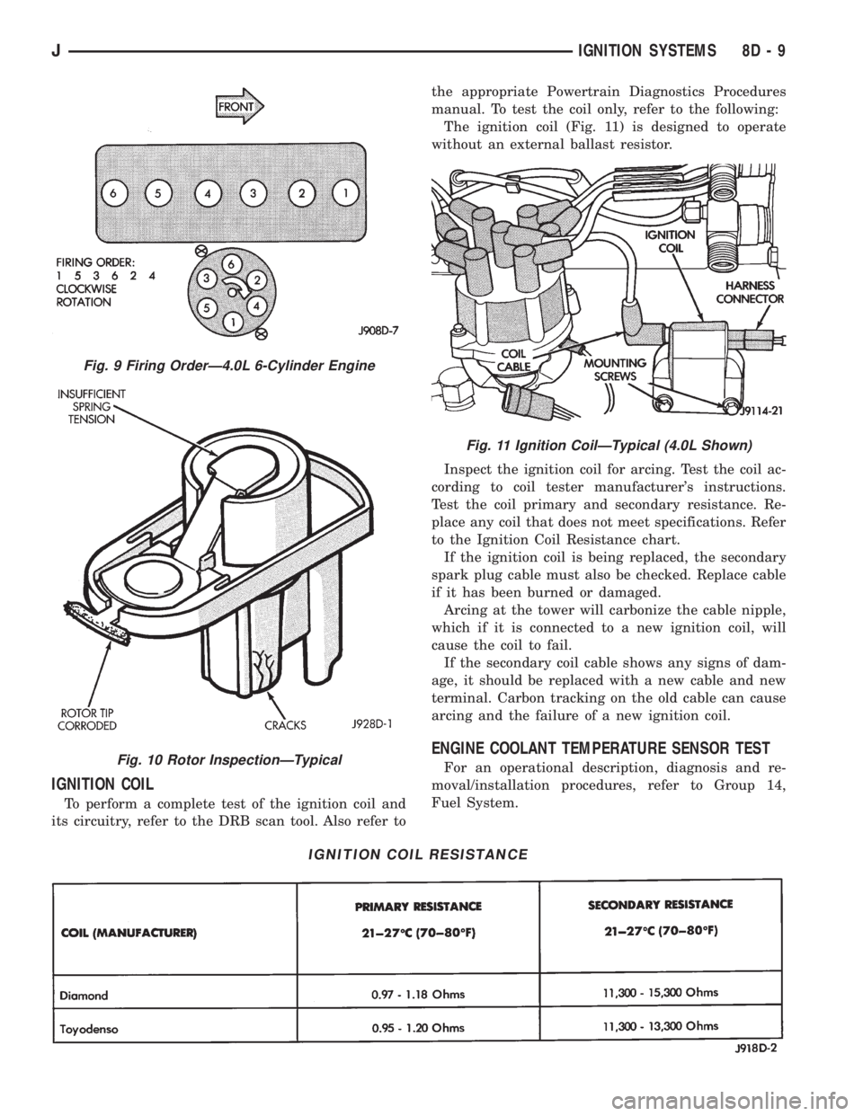
The ignition coil (Fig. 11) is designed to operate
without an external ballast resistor.
Inspect the ignition coil for arcing. Test the coil ac-
cording to coil tester manufacturer's instructions.
Test the coil primary and secondary resistance. Re-
place any coil that does not meet specifications. Refer
to the Ignition Coil Resistance chart.
If the ignition coil is being replaced, the secondary
spark plug cable must also be checked. Replace cable
if it has been burned or damaged.
Arcing at the tower will carbonize the cable nipple,
which if it is connected to a new ignition coil, will
cause the coil to fail.
If the secondary coil cable shows any signs of dam-
age, it should be replaced with a new cable and new
terminal. Carbon tracking on the old cable can cause
arcing and the failure of a new ignition coil.
ENGINE COOLANT TEMPERATURE SENSOR TEST
For an operational description, diagnosis and re-
moval/installation procedures, refer to Group 14,
Fuel System.
IGNITION COIL RESISTANCE
Fig. 9 Firing OrderÐ4.0L 6-Cylinder Engine
Fig. 10 Rotor InspectionÐTypical
Fig. 11 Ignition CoilÐTypical (4.0L Shown)
JIGNITION SYSTEMS 8D - 9
Page 335 of 2158
(4) Crank the engine for 5 seconds while monitor-
ing the voltage at the coil positive terminal:
²If the voltage remains near zero during the entire
period of cranking, refer to On-Board Diagnostics in
Group 14, Fuel Systems. Check the powertrain con-
trol module (PCM) and auto shutdown relay.
²If voltage is at or near battery voltage and drops
to zero after 1-2 seconds of cranking, check the cam-
shaft position sensor-to-PCM circuit. Refer to On-
Board Diagnostics in Group 14, Fuel Systems.
²If voltage remains at or near battery voltage dur-
ing the entire 5 seconds, turn the key off. Remove
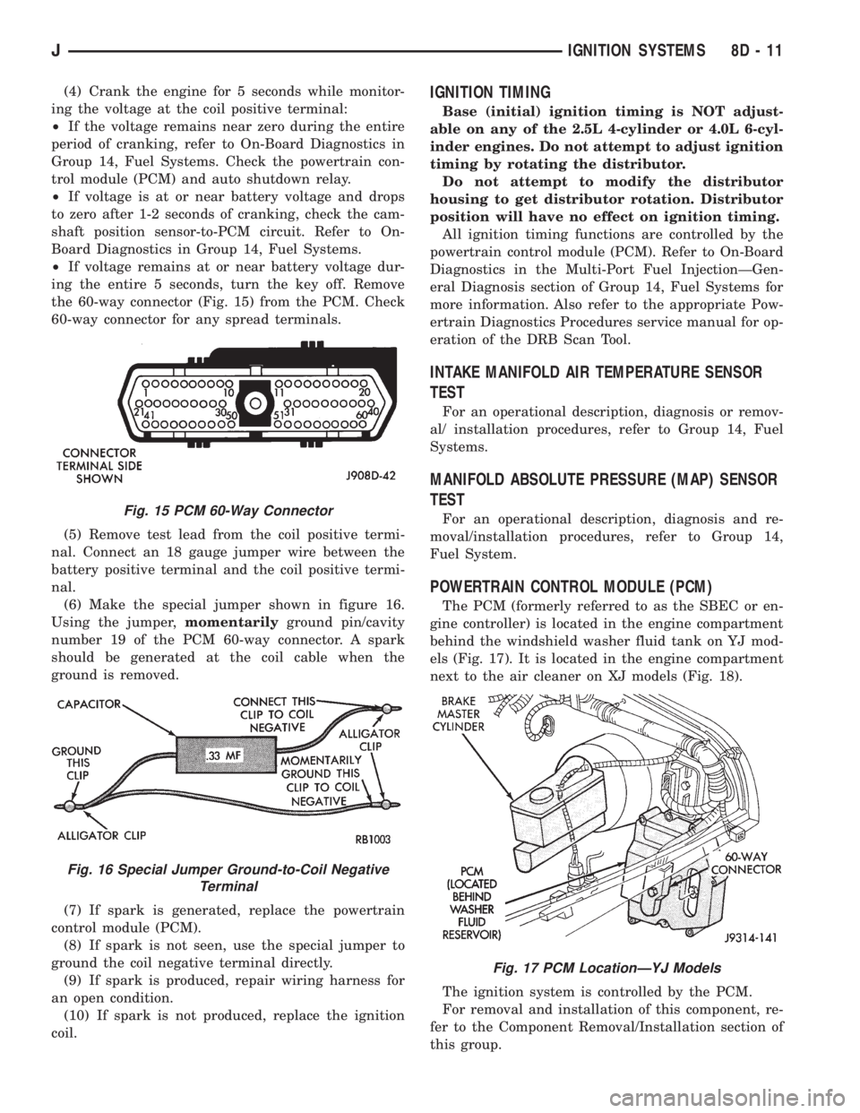
the 60-way connector (Fig. 15) from the PCM. Check
60-way connector for any spread terminals.
(5) Remove test lead from the coil positive termi-
nal. Connect an 18 gauge jumper wire between the
battery positive terminal and the coil positive termi-
nal.
(6) Make the special jumper shown in figure 16.
Using the jumper,momentarilyground pin/cavity
number 19 of the PCM 60-way connector. A spark
should be generated at the coil cable when the
ground is removed.
(7) If spark is generated, replace the powertrain
control module (PCM).
(8) If spark is not seen, use the special jumper to
ground the coil negative terminal directly.
(9) If spark is produced, repair wiring harness for
an open condition.
(10) If spark is not produced, replace the ignition
coil.IGNITION TIMING
Base (initial) ignition timing is NOT adjust-
able on any of the 2.5L 4-cylinder or 4.0L 6-cyl-
inder engines. Do not attempt to adjust ignition
timing by rotating the distributor.
Do not attempt to modify the distributor
housing to get distributor rotation. Distributor
position will have no effect on ignition timing.
All ignition timing functions are controlled by the
powertrain control module (PCM). Refer to On-Board
Diagnostics in the Multi-Port Fuel InjectionÐGen-
eral Diagnosis section of Group 14, Fuel Systems for
more information. Also refer to the appropriate Pow-
ertrain Diagnostics Procedures service manual for op-
eration of the DRB Scan Tool.
INTAKE MANIFOLD AIR TEMPERATURE SENSOR
TEST
For an operational description, diagnosis or remov-
al/ installation procedures, refer to Group 14, Fuel
Systems.
MANIFOLD ABSOLUTE PRESSURE (MAP) SENSOR
TEST
For an operational description, diagnosis and re-
moval/installation procedures, refer to Group 14,
Fuel System.
POWERTRAIN CONTROL MODULE (PCM)
The PCM (formerly referred to as the SBEC or en-
gine controller) is located in the engine compartment
behind the windshield washer fluid tank on YJ mod-
els (Fig. 17). It is located in the engine compartment
next to the air cleaner on XJ models (Fig. 18).
The ignition system is controlled by the PCM.
For removal and installation of this component, re-
fer to the Component Removal/Installation section of
this group.
Fig. 15 PCM 60-Way Connector
Fig. 16 Special Jumper Ground-to-Coil Negative
Terminal
Fig. 17 PCM LocationÐYJ Models
JIGNITION SYSTEMS 8D - 11
Page 339 of 2158
To test ignition coil-to-distributor cap cable, do not
remove the cable from the cap. Connect ohmmeter to
rotor button (center contact) of distributor cap and
terminal at ignition coil end of cable. If resistance is
not within specifications as found in the Spark Plug
Cable Resistance chart, remove the cable from the
distributor cap. Connect the ohmmeter to the termi-
nal ends of the cable. If resistance is not within spec-
ifications as found in the Spark Plug Cable
Resistance chart, replace the cable. Inspect the igni-
tion coil tower for cracks, burns or corrosion.
For removal and installation of spark plug cables,
refer to Spark Plug Secondary Cables in the Compo-
nent Removal/Installation section.
THROTTLE POSITION SENSOR TEST
For an operational description, diagnosis and re-
moval/installation procedures, refer to Group 14,
Fuel System.
OXYGEN (O2S) SENSOR TESTS
For an operational description, diagnosis or remov-
al/ installation procedures, refer to Group 14, Fuel
Systems.
ON-BOARD DIAGNOSTICS
FOR CERTAIN IGNITION SYSTEM
COMPONENTS
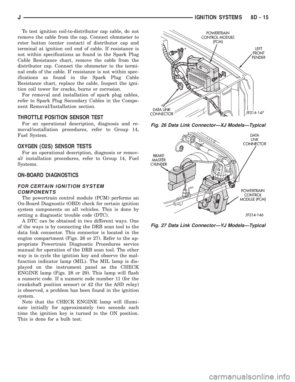
The powertrain control module (PCM) performs an
On-Board Diagnostic (OBD) check for certain ignition
system components on all vehicles. This is done by
setting a diagnostic trouble code (DTC).
A DTC can be obtained in two different ways. One
of the ways is by connecting the DRB scan tool to the
data link connector. This connector is located in the
engine compartment (Figs. 26 or 27). Refer to the ap-
propriate Powertrain Diagnostic Procedures service
manual for operation of the DRB scan tool. The other
way is to cycle the ignition key and observe the mal-
function indicator lamp (MIL). The MIL lamp is dis-
played on the instrument panel as the CHECK
ENGINE lamp (Figs. 28 or 29). This lamp will flash
a numeric code. If a numeric code number 11 (for the
crankshaft position sensor) or 42 (for the ASD relay)
is observed, a problem has been found in the ignition
system.
Note that the CHECK ENGINE lamp will illumi-
nate initially for approximately two seconds each
time the ignition key is turned to the ON position.
This is done for a bulb test.
Fig. 26 Data Link ConnectorÐXJ ModelsÐTypical
Fig. 27 Data Link ConnectorÐYJ ModelsÐTypical
JIGNITION SYSTEMS 8D - 15
Page 341 of 2158
COMPONENT REMOVAL/INSTALLATION
INDEX
page page
Automatic Shutdown (ASD) Relay............. 17
Camshaft Position Sensor................... 17
Crankshaft Position Sensor.................. 17
Distributor............................... 19
Engine Coolant Temperature Sensor........... 19
General Information....................... 17
Ignition Coil............................. 22Intake Manifold Air Temperature Sensor......... 23
Manifold Absolute Pressure (MAP) Sensor....... 23
Oxygen (O2S) Sensor...................... 23
Powertrain Control Module (PCM)............. 23
Spark Plug Secondary Cables................ 24
Spark Plugs............................. 23
Throttle Position Sensor (TPS)............... 25
GENERAL INFORMATION
This section of the group, Component Removal/In-
stallation, will discuss the removal and installation
of ignition system components.
For basic ignition system diagnostics and service
adjustments, refer to the Diagnostics/Service Proce-
dures section of this group.
For system operation and component identification,
refer to the Component Identification/System Opera-
tion section of this group.
AUTOMATIC SHUTDOWN (ASD) RELAY
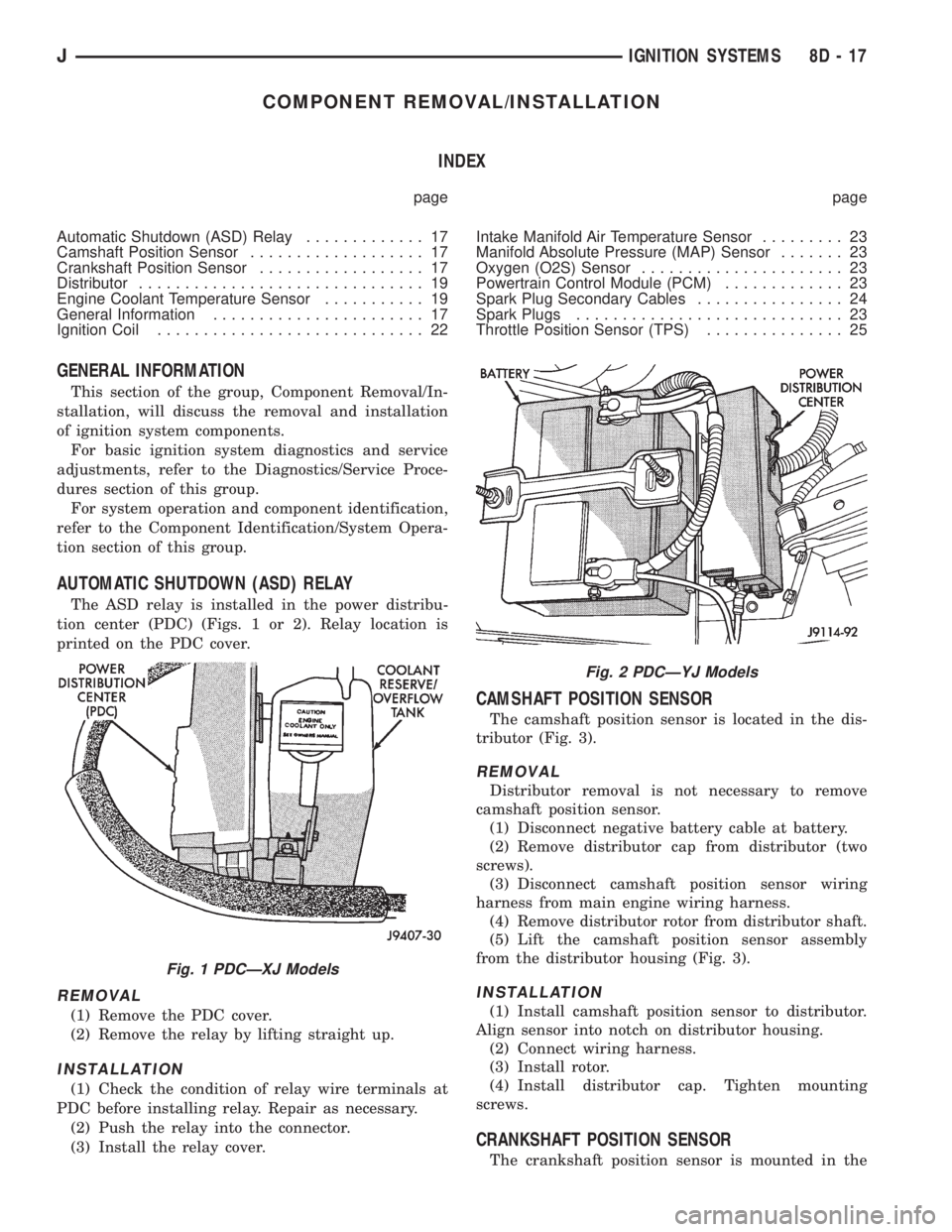
The ASD relay is installed in the power distribu-
tion center (PDC) (Figs. 1 or 2). Relay location is
printed on the PDC cover.
REMOVAL
(1) Remove the PDC cover.
(2) Remove the relay by lifting straight up.
INSTALLATION
(1) Check the condition of relay wire terminals at
PDC before installing relay. Repair as necessary.
(2) Push the relay into the connector.
(3) Install the relay cover.
CAMSHAFT POSITION SENSOR
The camshaft position sensor is located in the dis-
tributor (Fig. 3).
REMOVAL
Distributor removal is not necessary to remove
camshaft position sensor.
(1) Disconnect negative battery cable at battery.
(2) Remove distributor cap from distributor (two
screws).
(3) Disconnect camshaft position sensor wiring
harness from main engine wiring harness.
(4) Remove distributor rotor from distributor shaft.
(5) Lift the camshaft position sensor assembly
from the distributor housing (Fig. 3).
INSTALLATION
(1) Install camshaft position sensor to distributor.
Align sensor into notch on distributor housing.
(2) Connect wiring harness.
(3) Install rotor.
(4) Install distributor cap. Tighten mounting
screws.
CRANKSHAFT POSITION SENSOR
The crankshaft position sensor is mounted in the
Fig. 1 PDCÐXJ Models
Fig. 2 PDCÐYJ Models
JIGNITION SYSTEMS 8D - 17
Page 342 of 2158
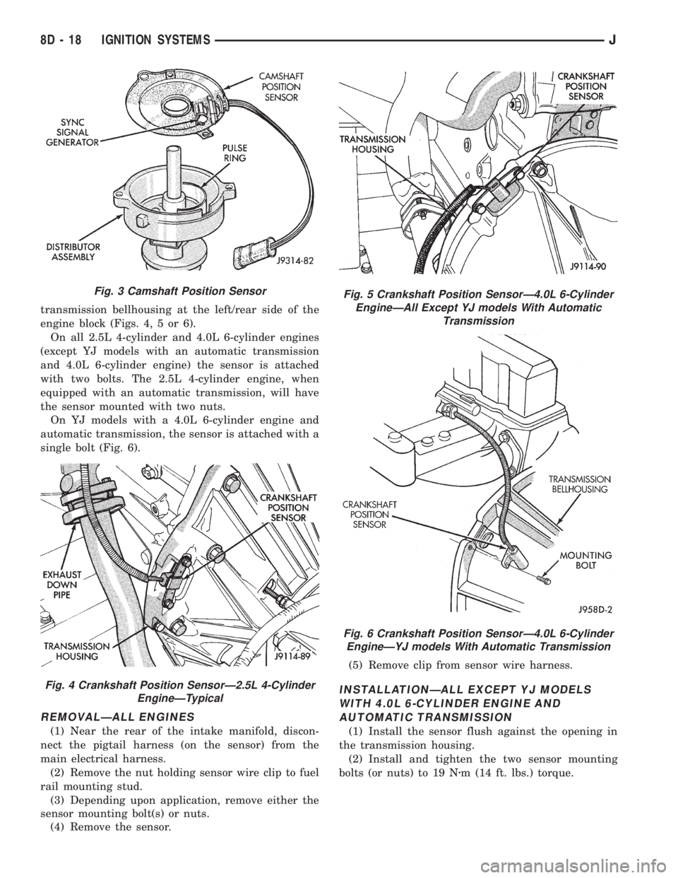
transmission bellhousing at the left/rear side of the
engine block (Figs. 4, 5 or 6).
On all 2.5L 4-cylinder and 4.0L 6-cylinder engines
(except YJ models with an automatic transmission
and 4.0L 6-cylinder engine) the sensor is attached
with two bolts. The 2.5L 4-cylinder engine, when
equipped with an automatic transmission, will have
the sensor mounted with two nuts.
On YJ models with a 4.0L 6-cylinder engine and
automatic transmission, the sensor is attached with a
single bolt (Fig. 6).
REMOVALÐALL ENGINES
(1) Near the rear of the intake manifold, discon-
nect the pigtail harness (on the sensor) from the
main electrical harness.
(2) Remove the nut holding sensor wire clip to fuel
rail mounting stud.
(3) Depending upon application, remove either the
sensor mounting bolt(s) or nuts.
(4) Remove the sensor.(5) Remove clip from sensor wire harness.
INSTALLATIONÐALL EXCEPT YJ MODELS
WITH 4.0L 6-CYLINDER ENGINE AND
AUTOMATIC TRANSMISSION
(1) Install the sensor flush against the opening in
the transmission housing.
(2) Install and tighten the two sensor mounting
bolts (or nuts) to 19 Nzm (14 ft. lbs.) torque.
Fig. 3 Camshaft Position Sensor
Fig. 4 Crankshaft Position SensorÐ2.5L 4-Cylinder
EngineÐTypical
Fig. 5 Crankshaft Position SensorÐ4.0L 6-Cylinder
EngineÐAll Except YJ models With Automatic
Transmission
Fig. 6 Crankshaft Position SensorÐ4.0L 6-Cylinder
EngineÐYJ models With Automatic Transmission
8D - 18 IGNITION SYSTEMSJ
Page 343 of 2158
CAUTION: On some models, two bolts are used to
secure the sensor to the transmission. These bolts
are specially machined to correctly space the unit
to the flywheel. Do not attempt to install any other
bolts.
(3) Connect the electrical connector to the sensor.
(4) Install clip on sensor wire harness.
(5) Install clip over fuel rail mounting stud. Install
clip mounting nut.
INSTALLATIONÐYJ MODELS WITH 4.0L
6-CYLINDER ENGINE AND AUTOMATIC
TRANSMISSION
(1) Install the sensor into the access hole on the
transmission.
(2) Install sensor mounting bolt (Fig. 6).
(3) Tighten sensor mounting bolt to 6-to-8 Nzm (50-
to-70 in. lbs.) torque.
(4) Connect the electrical connector to sensor.
(5) Install the clip to sensor wire harness.
(6) Install clip over fuel rail mounting stud. Install
clip mounting nut.
ENGINE COOLANT TEMPERATURE SENSOR
For an operational description, diagnosis and re-
moval/installation procedures, refer to Group 14,
Fuel System.
DISTRIBUTOR
GENERAL INFORMATION
All distributors contain an internal oil seal that
prevents oil from entering the distributor housing.
The seal is not serviceable.
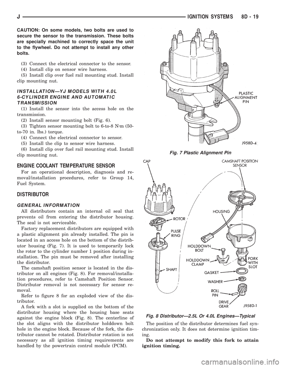
Factory replacement distributors are equipped with
a plastic alignment pin already installed. The pin is
located in an access hole on the bottom of the distrib-
utor housing (Fig. 7). It is used to temporarily lock
the rotor to the cylinder number 1 position during in-
stallation. The pin must be removed after installing
the distributor.
The camshaft position sensor is located in the dis-
tributor on all engines (Fig. 8). For removal/installa-
tion procedures, refer to Camshaft Position Sensor.
Distributor removal is not necessary for sensor re-
moval.
Refer to figure 8 for an exploded view of the dis-
tributor.
A fork with a slot is supplied on the bottom of the
distributor housing where the housing base seats
against the engine block (Fig. 8). The centerline of
the slot aligns with the distributor holddown bolt
hole in the engine block. Because of the fork, the dis-
tributor cannot be rotated. Distributor rotation is not
necessary as all ignition timing requirements are
handled by the powertrain control module (PCM).The position of the distributor determines fuel syn-
chronization only. It does not determine ignition tim-
ing.
Do not attempt to modify this fork to attain
ignition timing.
Fig. 7 Plastic Alignment Pin
Fig. 8 DistributorÐ2.5L Or 4.0L EnginesÐTypical
JIGNITION SYSTEMS 8D - 19
Page 345 of 2158
(2) Check the position of the slot on the oil pump
gear. On the 2.5L engine, it should be just slightly
before (counterclockwise of) the 10 o'clock position
(Fig. 10). On the 4.0L engine, it should be just
slightly before (counterclockwise of) the 11 o'clock po-
sition (Fig. 11). If not, place a flat blade screwdriver
into the oil pump gear and rotate it into the proper
position.
(3) Factory replacement distributors are equipped
with a plastic alignment pin already installed (Fig.
7). This pin is used to temporarily hold the rotor to
the cylinder number 1 firing position during distrib-
utor installation. If this pin is in place, proceed to
step number 8. If not, proceed to step number 4.
(4) If the original distributor is to be reinstalled,
such as during engine overhaul, the plastic pin will
not be available. A 3/16 inch drift pin punch tool may
be substituted for the plastic pin.
(5) Remove the camshaft position sensor from the
distributor housing. Lift straight up.
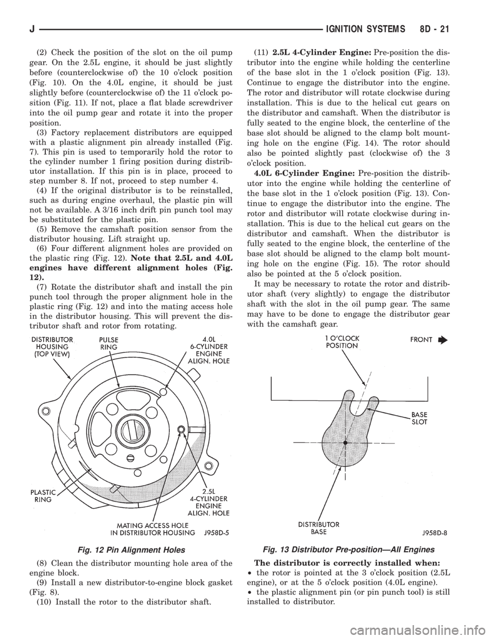
(6) Four different alignment holes are provided on
the plastic ring (Fig. 12).Note that 2.5L and 4.0L
engines have different alignment holes (Fig.
12).
(7) Rotate the distributor shaft and install the pin
punch tool through the proper alignment hole in the
plastic ring (Fig. 12) and into the mating access hole
in the distributor housing. This will prevent the dis-
tributor shaft and rotor from rotating.
(8) Clean the distributor mounting hole area of the
engine block.
(9) Install a new distributor-to-engine block gasket
(Fig. 8).
(10) Install the rotor to the distributor shaft.(11)2.5L 4-Cylinder Engine:Pre-position the dis-
tributor into the engine while holding the centerline
of the base slot in the 1 o'clock position (Fig. 13).
Continue to engage the distributor into the engine.
The rotor and distributor will rotate clockwise during
installation. This is due to the helical cut gears on
the distributor and camshaft. When the distributor is
fully seated to the engine block, the centerline of the
base slot should be aligned to the clamp bolt mount-
ing hole on the engine (Fig. 14). The rotor should
also be pointed slightly past (clockwise of) the 3
o'clock position.
4.0L 6-Cylinder Engine:Pre-position the distrib-
utor into the engine while holding the centerline of
the base slot in the 1 o'clock position (Fig. 13). Con-
tinue to engage the distributor into the engine. The
rotor and distributor will rotate clockwise during in-
stallation. This is due to the helical cut gears on the
distributor and camshaft. When the distributor is
fully seated to the engine block, the centerline of the
base slot should be aligned to the clamp bolt mount-
ing hole on the engine (Fig. 15). The rotor should
also be pointed at the 5 o'clock position.
It may be necessary to rotate the rotor and distrib-
utor shaft (very slightly) to engage the distributor
shaft with the slot in the oil pump gear. The same
may have to be done to engage the distributor gear
with the camshaft gear.
The distributor is correctly installed when:
²the rotor is pointed at the 3 o'clock position (2.5L
engine), or at the 5 o'clock position (4.0L engine).
²the plastic alignment pin (or pin punch tool) is still
installed to distributor.
Fig. 12 Pin Alignment HolesFig. 13 Distributor Pre-positionÐAll Engines
JIGNITION SYSTEMS 8D - 21
Page 347 of 2158
(3) Remove ignition coil mounting bolts (nuts are
used on back side of bracket). Remove coil.
INSTALLATION
(1) Install ignition coil to bracket on cylinder block
with mounting bolts and nuts.
(2) Connect engine harness connector to coil.
(3) Connect ignition coil cable to ignition coil.
INTAKE MANIFOLD AIR TEMPERATURE SENSOR
For an operational description, diagnosis or remov-
al/ installation procedures, refer to Group 14, Fuel
Systems.
MANIFOLD ABSOLUTE PRESSURE (MAP) SENSOR
For an operational description, diagnosis and re-
moval/installation procedures, refer to Group 14,
Fuel System.
OXYGEN (O2S) SENSOR
For an operational description, diagnosis or remov-
al/ installation procedures, refer to Group 14, Fuel
Systems.
POWERTRAIN CONTROL MODULE (PCM)
The PCM was formerly referred to as the SBEC or
engine controller.
XJ MODELS
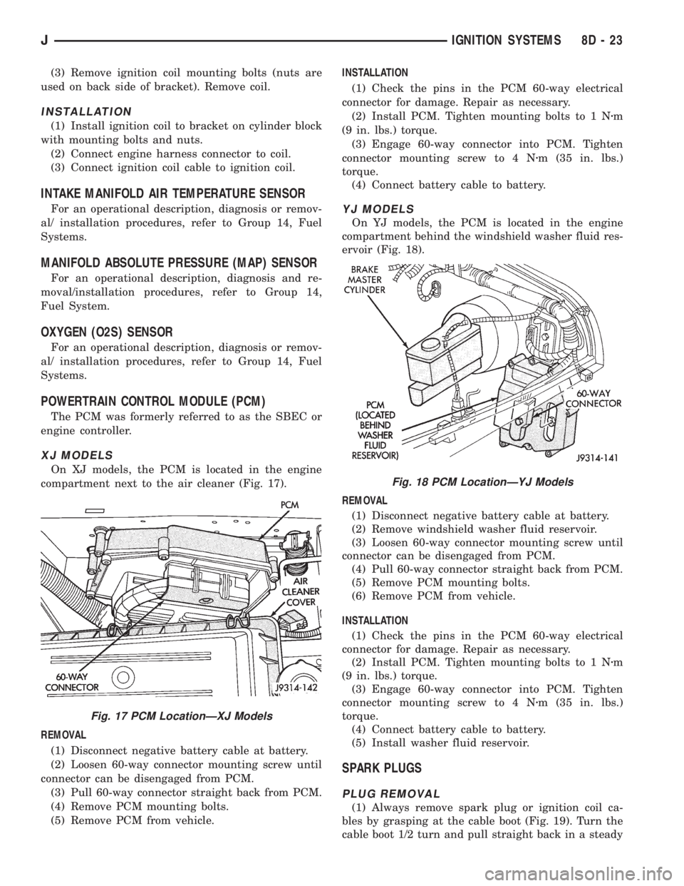
On XJ models, the PCM is located in the engine
compartment next to the air cleaner (Fig. 17).
REMOVAL
(1) Disconnect negative battery cable at battery.
(2) Loosen 60-way connector mounting screw until
connector can be disengaged from PCM.
(3) Pull 60-way connector straight back from PCM.
(4) Remove PCM mounting bolts.
(5) Remove PCM from vehicle.INSTALLATION
(1) Check the pins in the PCM 60-way electrical
connector for damage. Repair as necessary.
(2) Install PCM. Tighten mounting bolts to 1 Nzm
(9 in. lbs.) torque.
(3) Engage 60-way connector into PCM. Tighten
connector mounting screw to 4 Nzm (35 in. lbs.)
torque.
(4) Connect battery cable to battery.
YJ MODELS
On YJ models, the PCM is located in the engine
compartment behind the windshield washer fluid res-
ervoir (Fig. 18).
REMOVAL
(1) Disconnect negative battery cable at battery.
(2) Remove windshield washer fluid reservoir.
(3) Loosen 60-way connector mounting screw until
connector can be disengaged from PCM.
(4) Pull 60-way connector straight back from PCM.
(5) Remove PCM mounting bolts.
(6) Remove PCM from vehicle.
INSTALLATION
(1) Check the pins in the PCM 60-way electrical
connector for damage. Repair as necessary.
(2) Install PCM. Tighten mounting bolts to 1 Nzm
(9 in. lbs.) torque.
(3) Engage 60-way connector into PCM. Tighten
connector mounting screw to 4 Nzm (35 in. lbs.)
torque.
(4) Connect battery cable to battery.
(5) Install washer fluid reservoir.
SPARK PLUGS
PLUG REMOVAL
(1) Always remove spark plug or ignition coil ca-
bles by grasping at the cable boot (Fig. 19). Turn the
cable boot 1/2 turn and pull straight back in a steady
Fig. 17 PCM LocationÐXJ Models
Fig. 18 PCM LocationÐYJ Models
JIGNITION SYSTEMS 8D - 23