sensor JEEP YJ 1995 Service And Workshop Manual
[x] Cancel search | Manufacturer: JEEP, Model Year: 1995, Model line: YJ, Model: JEEP YJ 1995Pages: 2158, PDF Size: 81.9 MB
Page 436 of 2158
The two pivot cranks are joined by a connecting link,
and a drive link connects the motor crank to the drive
link near the left pivot. Pressed-in plastic bushings in
the ends of the links can be replaced if worn or dam-
aged.
WINDSHIELD WIPER MOTOR
The two-speed permanent magnet wiper motor has
an integral transmission and park switch. The motor
is mounted to the engine side of the cowl panel with
a reinforcement/stud plate and a rubber-isolated
mounting bracket. The wiper motor output shaft
passes through the cowl panel into the cowl plenum
area, where a crank arm attached to the output shaft
drives the wiper drive link.
Wiper speed is controlled by current flow to the ap-
propriate set of brushes. The wiper motor completes
its wipe cycle when the switch is turned OFF, and
parks the blades in the lowest portion of the wipe
pattern. The wiper motor assembly can not be re-
paired. If faulty, the entire motor assembly must be
replaced. The crank arm, mounting bracket, and re-
inforcement/stud plate are available for service.
LIFTGATE WIPER MOTOR
The liftgate wiper motor contains integral elec-
tronic controls and a transmission to provide three
operating modes:
²intermittent wipe with a fixed 5 to 8 second delay
between wipes
²constant wipe that operates when the liftgate
washer is operated
²a park mode that runs the motor until the wiper
blade reaches the park position after the liftgate
wiper switch or ignition switch is turned OFF.
The liftgate wiper motor can not be repaired. If
faulty, the entire assembly must be replaced.
WINDSHIELD WIPER/WASHER SWITCH
Controls for the windshield wiper and washer sys-
tems are contained in the multi-function switch con-
trol lever. The multi-function switch is mounted on
the left side of the steering column between the
steering wheel and the instrument panel. This switch
also controls many other functions. The multi-func-
tion switch can not be repaired. If any function of the
switch is faulty, the entire switch must be replaced.
LIFTGATE WIPER/WASHER SWITCH
The single two-function switch on the instrument
panel right of the steering column controls the lift-
gate wiper and washer functions. The rocker-type
switch features a detent in the WIPE position, but
only momentary contact in the WASH position. Both
the liftgate wiper and liftgate washer motors will op-
erate continuously for as long as the switch is held in
the WASH position. The switch can not be repaired;
if faulty, it must be replaced.
INTERMITTENT WIPE MODULE
In addition to low and high speed, the optional inter-
mittent wipe system has a delay mode. The delay mode
has a range of 2 to 15 seconds. The length of the delay
is selected with a variable resistor in the wiper (multi-
function) switch and is accomplished by electronic cir-
cuitry within the intermittent wipe module. If the
washer knob is depressed while the wiper (multi-func-
tion) switch is in the OFF position, the intermittent
wipe module will operate the wiper motor for approxi-
mately 2 wipes and automatically turn the motor off.
The intermittent wipe module is mounted to the
lower instrument panel, behind the knee blocker and
near the steering column with a hook and loop fas-
tener patch. The module can not be repaired.
WINDSHIELD WASHER NOZZLES
The two fluidic washer nozzles are riveted into
openings in the cowl grille panel below the wind-
shield and are not adjustable. Washer fluid is fed to
the nozzles through hoses clipped to the underside of
the cowl grille panel. The nozzles can not be repaired
and, if faulty, should be replaced.
LIFTGATE WASHER NOZZLE
The single liftgate washer nozzle snaps into place
on the liftgate wiper arm. Washer fluid is fed to the
nozzle from the washer reservoir in the engine com-
partment. A liftgate washer hose system is routed
through the body of the vehicle with the body wiring
harness from the reservoir to the liftgate. The fluid
passes through a nipple on the liftgate wiper motor
output shaft bezel to a hose clipped to the underside
of the wiper arm. The nozzle can not be repaired and,
if faulty, should be replaced.
WASHER RESERVOIR
The washer solvent reservoir is mounted to the left
front inner fender shield near the cowl panel. The
same reservoir is used for both the standard front
and optional liftgate washer systems. It also has a
provision for a low washer fluid level sensor. Refer to
Group 8E - Instrument Panel and Gauges for diagno-
sis and service of the sensor. The reservoir and filler
cap are available for service.
WASHER PUMPS
The washer pump and motor are press-fit into a
rubber grommet near the bottom of the washer res-
ervoir. Vehicles with the optional liftgate wiper/
washer system have two pumps installed in the
single reservoir. A permanently lubricated and sealed
motor is coupled to a rotor-type pump. Washer fluid
is gravity fed from the reservoir to the pump. The
pump then pressurizes the fluid and forces it through
the plumbing to the nozzles when the motor is ener-
gized. The pump and motor can not be repaired. If
faulty, the entire assembly must be replaced.
8K - 2 WIPER AND WASHER SYSTEMS - XJJ
Page 443 of 2158
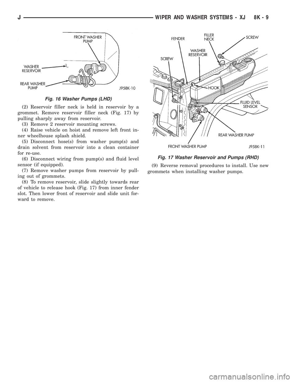
(2) Reservoir filler neck is held in reservoir by a
grommet. Remove reservoir filler neck (Fig. 17) by
pulling sharply away from reservoir.
(3) Remove 2 reservoir mounting screws.
(4) Raise vehicle on hoist and remove left front in-
ner wheelhouse splash shield.
(5) Disconnect hose(s) from washer pump(s) and
drain solvent from reservoir into a clean container
for re-use.
(6) Disconnect wiring from pump(s) and fluid level
sensor (if equipped).
(7) Remove washer pumps from reservoir by pull-
ing out of grommets.
(8) To remove reservoir, slide slightly towards rear
of vehicle to release hook (Fig. 17) from inner fender
slot. Then lower front of reservoir and slide unit for-
ward to remove.(9) Reverse removal procedures to install. Use new
grommets when installing washer pumps.
Fig. 16 Washer Pumps (LHD)
Fig. 17 Washer Reservoir and Pumps (RHD)
JWIPER AND WASHER SYSTEMS - XJ 8K - 9
Page 475 of 2158
DAYTIME RUNNING LIGHTS (CANADA ONLY)ÐXJ
SERVICE INFORMATION
The Daytime Running Lights (Headlamps) System
is installed on vehicles manufactured for sale in Can-
ada only. The headlamps are illuminated when the
ignition switch is turned to the ON position. The
DRL module receives a vehicle-moving signal from
the vehicle speed sensor. This provides a constant
headlamps-oncondition as long as the vehicle is
moving. The lamps are illuminated at less than 50
percent of normal intensity.
DRL MODULE REPLACEMENTÐXJ
REMOVAL
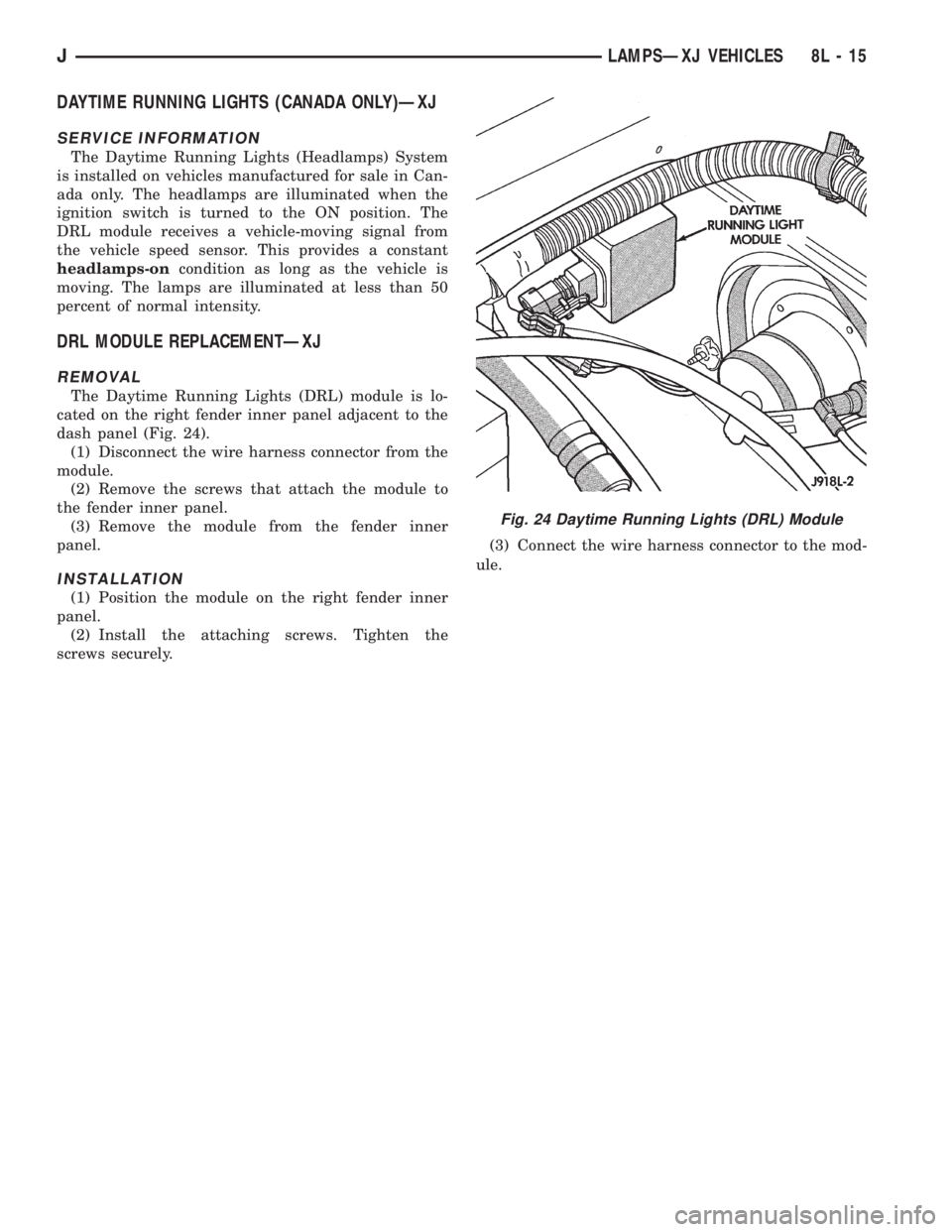
The Daytime Running Lights (DRL) module is lo-
cated on the right fender inner panel adjacent to the
dash panel (Fig. 24).
(1) Disconnect the wire harness connector from the
module.
(2) Remove the screws that attach the module to
the fender inner panel.
(3) Remove the module from the fender inner
panel.
INSTALLATION
(1) Position the module on the right fender inner
panel.
(2) Install the attaching screws. Tighten the
screws securely.(3) Connect the wire harness connector to the mod-
ule.
Fig. 24 Daytime Running Lights (DRL) Module
JLAMPSÐXJ VEHICLES 8L - 15
Page 490 of 2158
(3) Insert a replacement bulb in the lamp base
socket and rotate it clockwise.
(4) Connect the wire harness connector to the
lamp.
DAYTIME RUNNING LIGHTS (CANADA ONLY)ÐYJ
The Daytime Running Lights (Headlamps) System
is installed on vehicles manufactured for sale in Can-
ada only. The headlamps are illuminated when the
ignition switch is turned to the ON position. The
DRL module receives a vehicle-moving signal from
the vehicle speed sensor. This provides a constant
headlamps-oncondition as long as the vehicle is
moving. The lamps are illuminated at less than 50
percent of normal intensity.
DRL MODULE REPLACEMENTÐYJ
REMOVAL
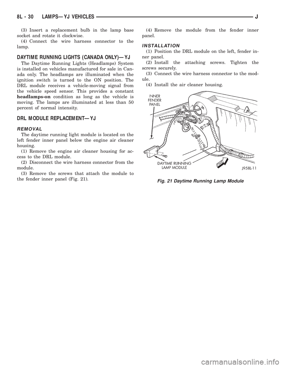
The daytime running light module is located on the
left fender inner panel below the engine air cleaner
housing.
(1) Remove the engine air cleaner housing for ac-
cess to the DRL module.
(2) Disconnect the wire harness connector from the
module.
(3) Remove the screws that attach the module to
the fender inner panel (Fig. 21).(4) Remove the module from the fender inner
panel.
INSTALLATION
(1) Position the DRL module on the left, fender in-
ner panel.
(2) Install the attaching screws. Tighten the
screws securely.
(3) Connect the wire harness connector to the mod-
ule.
(4) Install the air cleaner housing.
Fig. 21 Daytime Running Lamp Module
8L - 30 LAMPSÐYJ VEHICLESJ
Page 493 of 2158
RESTRAINT SYSTEMS
CONTENTS
page page
AIRBAG SYSTEM......................... 1
DIAGNOSIS............................. 2GENERAL INFORMATION.................. 1
SERVICE PROCEDURES................... 2
AIRBAG SYSTEM
WARNING: THIS AIRBAG SYSTEM IS A SENSITIVE,
COMPLEX MECHANICAL UNIT. BEFORE ATTEMPT-
ING TO REMOVE OR INSTALL THE AIRBAG SYS-
TEM OR RELATED STEERING WHEEL AND
STEERING COLUMN COMPONENTS YOU MUST
FIRST DISARM THE AIRBAG FIRING MECHANISM.
FAILURE TO DO SO COULD RESULT IN ACCIDEN-
TAL DEPLOYMENT AND POSSIBLE PERSONAL IN-
JURY.
WARNING: THE AIRBAG MODULE INFLATOR/SEN-
SOR ASSEMBLY CONTAINS SODIUM AZIDE AND
POTASSIUM NITRATE. THESE MATERIALS ARE
POISONOUS AND EXTREMELY FLAMMABLE. CON-
TACT WITH ACID, WATER OR HEAVY METALS MAY
PRODUCE HARMFUL AND IRRITATING GASES (SO-
DIUM HYDROXIDE IS FORMED IN THE PRESENCE
OF MOISTURE) OR COMBUSTIBLE COMPOUNDS.
DO NOT ATTEMPT TO DISMANTLE THE MODULE
OR TAMPER WITH ITS ARMING LEVER. DO NOT
PUNCTURE, INCINERATE, OR BRING INTO CON-
TACT WITH ELECTRICITY. DO NOT STORE AT TEM-
PERATURES EXCEEDING 200ÉF.WARNING: REPLACE AIRBAG SYSTEM COMPO-
NENTS WITH PARTS SPECIFIED IN THE CHRYSLER
MOPAR PARTS CATALOG ONLY. IT IS OF PARTICU-
LAR IMPORTANCE THAT ANY COMPONENTS USED
IN THIS MECHANICALLY-FIRED AIRBAG SYSTEM
NOT BE MIXED WITH COMPONENTS FROM AN
ELECTRICALLY-FIRED AIRBAG SYSTEM. SUBSTI-
TUTE PARTS MAY APPEAR THE SAME, BUT INTER-
NAL DIFFERENCES MAY RESULT IN INFERIOR
OCCUPANT PROTECTION.
WARNING: THE FASTENERS, SCREWS, AND
BOLTS, ORIGINALLY USED FOR THE AIRBAG COM-
PONENTS, HAVE SPECIAL COATINGS AND ARE
SPECIFICALLY DESIGNED FOR THE AIRBAG SYS-
TEM. THEY MUST NEVER BE REPLACED WITH ANY
SUBSTITUTES. ANYTIME A NEW FASTENER IS
NEEDED, REPLACE WITH THE CORRECT FASTEN-
ERS PROVIDED IN THE SERVICE PACKAGE OR
SPECIFIED IN THE CHRYSLER MOPAR PARTS CAT-
ALOG.
GENERAL INFORMATION
The airbag system is a standard equipment safety
device on XJ (Cherokee) models. It is designed to pro-
tect the driver from serious injury, caused by a fron-
tal impact of the vehicle. If the airbag module
assembly is defective and non-deployed, refer to
Chrysler Corporation current return list for proper
handling procedures.
Following are general descriptions of the major
components in the airbag system.AIRBAG MODULE
The airbag module protective cover is the only vis-
ible part of the system. The module is mounted di-
rectly to the steering wheel. Under the airbag
module cover, the airbag cushion and its supporting
components are contained. The airbag module con-
tains a housing to which the cushion and impact sen-
sor/inflator assembly are attached and sealed. The
airbag module is non-serviceable, and must be re-
placed if deployed or damaged in any way.
The impact sensor/inflator assembly is mounted to
the back of the module. The inflator seals the hole in
JRESTRAINT SYSTEMS 8M - 1
Page 494 of 2158
the airbag cushion so it can discharge the gas it pro-
duces directly into the cushion. The protective cover
is fitted to the front of the airbag module and forms
a decorative cover in the center of the steering wheel.
Upon airbag deployment, this cover will split hori-
zontally.
STORAGE
The airbag module must be stored in its original,
special container until used for service. Also, it must
be stored in a clean, dry environment; away from
sources of extreme heat, sparks, and high electrical
energy. Always place or store the module on a surface
with the trim cover facing up to minimize movement
in case of accidental deployment.
IMPACT SENSOR/INFLATOR ASSEMBLY
The impact sensor/inflator assembly is mounted to
the back of the airbag module. It seals the hole in
the steering wheel side of the airbag cushion so that
gas produced in the inflator can be discharged di-
rectly into the cushion.
The impact sensor provides verification of the di-
rection and severity of the impact. A spherical sens-
ing mass housed in a cylinder will move forward and
rotate a D-shaft when the vehicle is subjected to a
frontal impact of sufficient severity. Airbag inflation
is designed to occur at a precisely calibrated vehicle
deceleration force, and is not linked to vehicle road
speed.The D-shaft retains two spring-loaded firing pins.
When a firing pin is released by the D-shaft, it
strikes and ignites a primer. The primer then reacts
with the pelletized, solid generant contained in the
inflator to produce the nitrogen gas that inflates the
airbag cushion.
ARMING/DISARMING MECHANISM
The steering wheel hub incorporates an airbag
arming/disarming mechanism and a specially de-
signed nut-blocker. The nut-blocker serves as a safety
to prevent removal of the airbag module until the
unit has been disarmed. A removable plastic cover
plug on the top, outer hub of the steering wheel al-
lows access to the arming screw.
When the airbag module is disarmed, the arming
screw extends upward from the steering wheel hub.
This will prevent installation of the plastic cover
plug. Also, the nut-blocker is retracted to allow ac-
cess to the two upper airbag module mounting nuts.
When the airbag module is armed, the plastic cover
plug will install flush with the outer surface of the
steering wheel hub. In addition, the nut-blocker will
prevent access to the two upper airbag module
mounting nuts.
DIAGNOSIS
This mechanical airbag system can not be diag-
nosed or repaired. The only serviced component is
the airbag module assembly. If the airbag module isdamaged in any way or deployed, it must be re-
placed.
SERVICE PROCEDURES
AIRBAG SYSTEM SERVICE (DEPLOYED)
Any vehicle which is to be returned to use after an
airbag deployment, must have the airbag module re-
placed. This is a one-time component and cannot be
reused.
AIRBAG MODULE HANDLING
UNDEPLOYED
At no time should any source of electricity be per-
mitted near the inflator on the back of the module.
When carrying an undeployed module, the trim cover
should be pointed away from the body to minimizeinjury in the event of accidental deployment. If the
module is placed on a bench or other surface, the
plastic trim cover should be face up to minimize
movement in case of accidental deployment.
In addition, the airbag module should be disarmed
whenever the steering wheel or steering column re-
quires service or removal. Failure to observe this
warning could result in accidental airbag deployment
and possible personal injury. Refer to Group 19 -
Steering for more service procedures on steering
wheel and steering column.
8M - 2 RESTRAINT SYSTEMSJ
Page 581 of 2158
CHARGING SYSTEM
CHARGING SYSTEM
The charging system is an integral part of the bat-
tery and starting systems. Because all these systems
work in conjunction, diagnose and test them together.
Circuit A11 connects to the generator output termi-
nal and splices to fuse 1 and fuse 8 in the Power Dis-
tribution Center (PDC). Circuit A0 connects the
battery to the PDC.
Circuit Z0 provides ground for the generator. Cir-
cuit Z0 attaches to the right rear of the engine.
When the ignition switch is in either the START or
RUN positions, it connects circuit A1 from fuse 6 in
the PDC to circuit A21. Circuit A21 splices to supply
current to the coil side of the automatic shut down
(ASD) relay. The powertrain control module (PCM)
provides ground for the relay on circuit K51. Circuit
K51 connects to cavity 51 of the PCM.
When the PCM grounds the ASD relay, contacts in-
side the relay close and connect circuit A18 from fuse
14 in the PDC to circuit A142. Circuit A142 splices to
the generator field terminal.
The PCM has an internal voltage regulator that
controls generator output. The PCM controls the gen-
erator field on circuit K20. Circuit K20 connects to
PCM cavity 20.
When the engine operates and there is current in
the generator field, the generator produces a B+ volt-
age. The generator supplies B+ voltage to the battery
through the A11 and A0 circuits.
HELPFUL INFORMATION
²If the vehicle is equipped with a 2.5L engine, cir-
cuit Z0 also connects to the battery.
²Circuit A14 from fuse 2 in the PDC supplies volt-
age to the fuse block for fuse 14.
²The ignition switch also connects circuit A1 with
circuits A41, A38, and A48.
²Circuit A21 also splices to power fuse 17 in the
fuse block.
²Circuit A21 also powers the coil side of the fuel
pump relay.
²The ASD relay supplies battery voltage for the fuel
injectors, ignition coil, and the heated oxygen sensor.
The fuel pump relay powers the fuel pump module.
²Circuit K51 also provides ground for the coil side
of the fuel pump relay.
DIAGRAM INDEX
Component Page
Battery (2.5L)...........................8W-20-2
Battery (4.0L)...........................8W-20-3
PDC Fuse 1 (2.5L).......................8W-20-2
PDC Fuse 1 (4.0L).......................8W-20-3
PDC Fuse 9 (2.5L).......................8W-20-2
PDC Fuse 9 (4.0L).......................8W-20-3
Generator (2.5L).........................8W-20-2
Generator (4.0L).........................8W-20-3
Powertrain Control Module (2.5L)..............8W-20-2
Powertrain Control Module (4.0L)..............8W-20-3
J8W-20 CHARGING SYSTEMÐXJ VEHICLES 8W - 20 - 1
Page 589 of 2158
FUEL/IGNITION
INDEX
page page
Automatic Shut Down (ASD) Relay............. 1
Battery Feed.............................. 1
Brake Switch Input......................... 5
Camshaft Position Sensor.................... 3
CCDBus ................................ 5
Crankshaft Position Sensor................... 3
Data Link Connector........................ 5
Diagram Index Ð2.5L Engine.................. 6
Diagram Index Ð4.0L Engine.................. 6
Engine Coolant Temperature Sensor............ 3
Extended Idle Switch....................... 5
Fuel Injectors............................. 1
Fuel Pump Module......................... 2
Fuel Pump Relay.......................... 2
Heated Oxygen Sensor...................... 3Idle Air Control (IAC) Motor................... 2
Ignition Coil.............................. 2
Ignition Switch............................ 1
Intake Air Temperature Sensor................ 4
Malfunction Indicator Lamp (MIL)............... 5
Manifold Absolute Pressure Sensor............. 4
Park/Neutral Position Switch.................. 4
Power (Device) Ground...................... 5
Power Steering Pressure Switch............... 5
Tachometer Signal......................... 5
Throttle Position Sensor..................... 4
Torque Converter Clutch (TCC) Solenoid and
Relay................................. 4
Upshift Lamp............................. 5
Vehicle Speed Sensor....................... 2
IGNITION SWITCH
Circuit A1 from fuse 11 in the power distribution
center (PDC), supplies battery voltage to the ignition
switch. Depending upon position, the ignition switch
powers circuits A21, A38, A41, or A48.
START POSITION
In the START position, the ignition switch connects
circuit A1 to circuit A41. Circuit A41 connects to the
coil side of the starter motor relay.
Additionally in the START position, the case
grounded ignition switch provides ground for the
brake lamp switch and the warning lamps in the
instrument cluster.
START OR RUN POSITION
In the START or RUN position, the ignition switch
connects circuit A1 to circuit A21. Circuit A21 splices
to power fuse 17 in the fuse block and the coil side of
the Automatic Shut Down (ASD) relay and the fuel
pump relay.
RUN (ONLY) POSITION
When the ignition switch is in the RUN position, it
connects circuit A1 to circuit A38. Circuit A22 splices
to power fuses 1 and 7 in the fuse block.
²Fuse 1 powers the rear wiper system on circuit
V15.
²Fuse 7 feeds the Anti-Lock Brake System (ABS) on
circuit 236.
ACCESSORY OR RUN POSITIONS
In the ACCESSORY or RUN positions, the ignition
switch connects circuit A1 to circuit A48. Circuit A48
connects to a bus bar in the fuse block that feeds
fuses 2, 5, and 8.
AUTOMATIC SHUT DOWN (ASD) RELAY
When the ignition switch is in either the START or
RUN positions, it connects circuit A1 from fuse 6 in
the Power Distribution Center (PDC) to circuit A21.
Circuit A21 supplies battery voltage to the coil side of
the Automatic Shut Down (ASD) relay. The Power-
train Control Module (PCM) provides ground for the
relay on circuit K51. Circuit K51 connects to cavity 51
of the PCM.
When the PCM grounds the ASD relay, contacts
inside the relay close and connect circuit A18 from
fuse 14 in the PDC to circuit A142. Circuit A142
splices to the generator field terminal, fuel injectors,
and ignition coil. Circuit A142 also connects to cavity
57 of the PCM.
HELPFUL INFORMATION
²Along with supplying voltage to the coil side of the
ASD relay, circuit A21 also supplies voltage to the coil
side of the fuel pump relay.
BATTERY FEED
Circuit A14 from fuse 2 in the Power Distribution
Center (PDC) supplies battery voltage to cavity 3 of
the powertrain control module.
HELPFUL INFORMATION
Circuit A14 also supplies power to the contact sides
of the fuel pump relay and fuse F2 in the PDC. Fuse
F2 powers circuit A18 which supplies voltage to the
contact side of the automatic shut down relay.
FUEL INJECTORS
When the Automatic Shut Down (ASD) relay con-
tacts close, they connect circuits A14 and A142. Cir-
J8W-30 FUEL/IGNITIONÐXJ VEHICLES 8W - 30 - 1
Page 590 of 2158
cuit A142 supplies voltage to the fuel injectors. Each
injector has a separate ground circuit controlled by
the PCM.
Circuit K11 provides ground for injector number
one. The K11 circuit connects to cavity 16 of the
PCM.
Circuit K12 provides ground for injector number
two. The K12 circuit connects to cavity 15 of the
PCM.
Circuit K13 provides ground for injector number
three. The K13 circuit connects to cavity 14 of the
PCM.
Circuit K14 provides ground for injector number
four. The K14 circuit connects to cavity 13 of the
PCM.
On the 4.0L engine, circuit K15 provides ground for
injector number five. The K15 circuit connects to cav-
ity 38 of the PCM.
Also on the 4.0L engine, circuit K16 provides
ground for injector number six. The K16 circuit con-
nects to cavity 58 of the PCM.
HELPFUL INFORMATION
²Circuit A142 splices to supply voltage to the fuel
injectors, ignition coil, PCM, generator.
²For information about fuel injector operation, refer
to Group 14.
IGNITION COIL
When the Automatic Shut Down (ASD) relay con-
tacts close, they connect circuits A14 and A142. Cir-
cuit A142 supplies voltage to the fuel injectors.
Circuit A142 splices to supply voltage to the ignition
coil. The PCM controls the ground path for the igni-
tion coil on circuit K19. Circuit K19 connects to cav-
ity 19 of the PCM.
HELPFUL INFORMATION
Circuit A142 splices to supply voltage to the fuel
injectors, ignition coil, PCM, and generator.
FUEL PUMP RELAY
When the ignition switch is in either the START or
RUN positions, it connects circuit A1 from fuse 6 in
the Power Distribution Center (PDC) to circuit A21.
Circuit A21 supplies battery voltage to the coil side of
the fuel pump relay. The Powertrain Control Module
(PCM) provides ground for the relay on circuit K51.
Circuit K51 connects to cavity 51 of the PCM.
When the PCM grounds the fuel pump relay, con-
tacts inside the relay close and connect circuit A14
from fuse 2 in the PDC to circuit A141. Circuit A141
supplies voltage to the fuel pump motor (part of the
in-tank fuel pump module).
HELPFUL INFORMATION
²Circuit A14 also splices to supply battery voltage
to cavity 3 of the PCM.²Circuit A141 also supplies battery voltage to the
heated oxygen sensor.
FUEL PUMP MODULE
FUEL PUMP MOTOR
When the fuel pump relay contacts close, the relay
supplies voltage to the fuel pump motor. Circuit A141
from the relay supplies voltage to circuit A241. Cir-
cuit A241 connects to circuit F9 in the fuel pump
module harness. Circuit F9 connects to the fuel pump
motor.
Circuit 99 in the fuel pump module harness con-
nects to circuit Z1. Circuit Z1 provides ground for the
fuel pump motor.
FUEL LEVEL SENSOR
The fuel level sensor is a variable resistor. Circuit
G4 connects the fuel level sensor to the fuel gauge in
the instrument cluster. Circuit F87 from fuse 17 in
the fuse block supplies voltage to the fuel gauge. The
fuel level sensor draws voltage from circuit F87
through the fuel gauge on circuit G4. Circuit G4 con-
nects to circuit 57 in the fuel pump module harness.
Circuit 57 connects to the fuel level sensor.
Circuit 99 in the fuel pump module harness con-
nects to circuit Z1. Circuit Z1 provides the ground
path for the fuel level sensor. The grounding point for
circuit Z1 is the left side of the cowl panel.
HELPFUL INFORMATION
As current flows through the coils in the fuel
gauge, it creates a magnetic field. One of the coils in
the gauge receives fixed current. The other coil is
connected to the level sensor. The magnetic field con-
trols the position of the fuel gauge pointer.
The fuel level sensor contains a variable resistor.
As the position of the float arm on the fuel level sen-
sor changes, the resistor changes the current flow
through second coil in the fuel gauge. A change in
current flow alters the magnetic field in the fuel
gauge, which changes the pointer position.
IDLE AIR CONTROL (IAC) MOTOR
The Powertrain Control Module (PCM) operates
the idle air control motor through 4 circuits - K39,
K40, K59, and K60. Each circuit connects to separate
cavities in the PCM connector.
²Circuit K39 connects to cavity 39 of the PCM
²Circuit K40 connects to cavity 40 of the PCM
²Circuit K59 connects to cavity 59 of the PCM
²Circuit K60 connects to cavity 60 of the PCM
VEHICLE SPEED SENSOR
Circuit K7 supplies 8 volts from the Powertrain
Control Module (PCM) to the vehicle speed sensor.
The K7 circuit connects to cavity 7 of the PCM.
8W - 30 - 2 8W-30 FUEL/IGNITIONÐXJ VEHICLESJ
Page 591 of 2158
Circuit G7 from the vehicle speed sensor provides
an input signal to the PCM. The G7 circuit connects
to cavity 47 of the PCM.
The PCM provides a ground for the vehicle speed
sensor signal (circuit G7) through circuit K4. Circuit
K4 connects to cavity 4 of the PCM.
HELPFUL INFORMATION
²Circuit G7 splices to the speedometer, and daytime
running lights module (DRL).
²Circuit K7 splices to supply 8 volts to the camshaft
position sensor and crankshaft position sensor.
Circuit K4 splices to supply ground for the signals
from the following:
²Heated oxygen sensor
²Camshaft position sensor
²Crankshaft position sensor
²Throttle position sensor
²Manifold absolute pressure sensor
²Engine coolant temperature sensor
²Intake air temperature sensor
HEATED OXYGEN SENSOR
When the fuel pump relay contacts close, they con-
nect circuits A14 and A141. Circuit A141 splices to
supply voltage to the heated oxygen sensor.
Circuit K41 delivers the signal from the heated ox-
ygen sensor to the PCM. Circuit K41 connects to cav-
ity 41 of the PCM.
The PCM provides a ground for the heated oxygen
sensor signal (circuit K41) through circuit K4. Circuit
K4 connects to cavity 4 of the PCM connector.
Circuit Z12 provides a ground for the heater circuit
in the sensor.
Circuit Z12 terminates at the right side of the en-
gine.
HELPFUL INFORMATION
²Circuit A141 also supplies battery voltage to the
fuel pump.
Circuit K4 splices to supply ground for the signals
from the following:
²Heated oxygen sensor
²Camshaft position sensor
²Crankshaft position sensor
²Intake air temperature sensor
²Throttle position sensor
²Manifold absolute pressure sensor
²Engine coolant temperature sensor
²Vehicle speed sensor
CAMSHAFT POSITION SENSOR
The Powertrain Control Module (PCM) supplies 8
volts to the camshaft position sensor (in distributor)
on circuit K7. Circuit K7 connects to cavity 7 of the
PCM.The PCM receives the camshaft position sensor sig-
nal on circuit K44. Circuit K44 connects to cavity 44
of the PCM.
The PCM provides a ground for the camshaft posi-
tion sensor signal (circuit K44) through circuit K4.
Circuit K4 connects to cavity 4 of the PCM.
HELPFUL INFORMATION
²Circuit K7 splices to supply 8 volts to the crank-
shaft position sensor and the vehicle speed sensor.
Circuit K4 splices to supply ground for the signals
from the following:
²Heated oxygen sensor
²Camshaft position sensor
²Crankshaft position sensor
²Intake air temperature sensor
²Throttle position sensor
²Manifold absolute pressure sensor
²Engine coolant temperature sensor
²Vehicle speed sensor
CRANKSHAFT POSITION SENSOR
The Powertrain Control Module (PCM) supplies 8
volts to the crankshaft position sensor on circuit K7.
Circuit K7 connects to cavity 7 of the PCM.
The PCM receives the crankshaft position sensor
signal on circuit K24. Circuit K24 connects to cavity
24 of the PCM.
The PCM provides a ground for the crankshaft po-
sition sensor (circuit K24) through circuit K4. Circuit
K4 connects to cavity 4 of the PCM.
HELPFUL INFORMATION
²Circuit K7 splices to supply 8 volts to the camshaft
position sensor and the vehicle speed sensor.
Circuit K4 splices to supply ground for the signals
from the following:
²Heated oxygen sensor
²Camshaft position sensor
²Crankshaft position sensor
²Intake air temperature sensor
²Throttle position sensor
²Manifold absolute pressure sensor
²Engine coolant temperature sensor
²Vehicle speed sensor
ENGINE COOLANT TEMPERATURE SENSOR
The engine coolant temperature sensor provides an
input to the Powertrain Control Module (PCM) on
circuit K2. From circuit K2, the engine coolant tem-
perature sensor draws up to 5 volts from the PCM.
The sensor is a variable resistor. As coolant temper-
ature changes, the resistance in the sensor changes,
causing a change in current draw. The K2 circuit
connects to cavity 2 of the PCM.
J8W-30 FUEL/IGNITIONÐXJ VEHICLES 8W - 30 - 3