frame JEEP YJ 1995 Service And Repair Manual
[x] Cancel search | Manufacturer: JEEP, Model Year: 1995, Model line: YJ, Model: JEEP YJ 1995Pages: 2158, PDF Size: 81.9 MB
Page 3 of 2158
GROUP TAB LOCATOR
Introduction
0Lubrication and Maintenance
2Front Suspension and Axle
3Rear Suspension and Axles
5Brakes
6Clutch
7Cooling System
8Electrical
9Engines
11Exhaust System and Intake Manifold
13Frame and Bumpers
14Fuel System
16Propeller Shafts
19Steering
21Transmission and Transfer Cases
22Wheels and Tires
23Body Components
24Heating and Air Conditioning
25Emission Control Systems
Index
Service Manual Comment Forms (Rear of Manual)
Page 7 of 2158
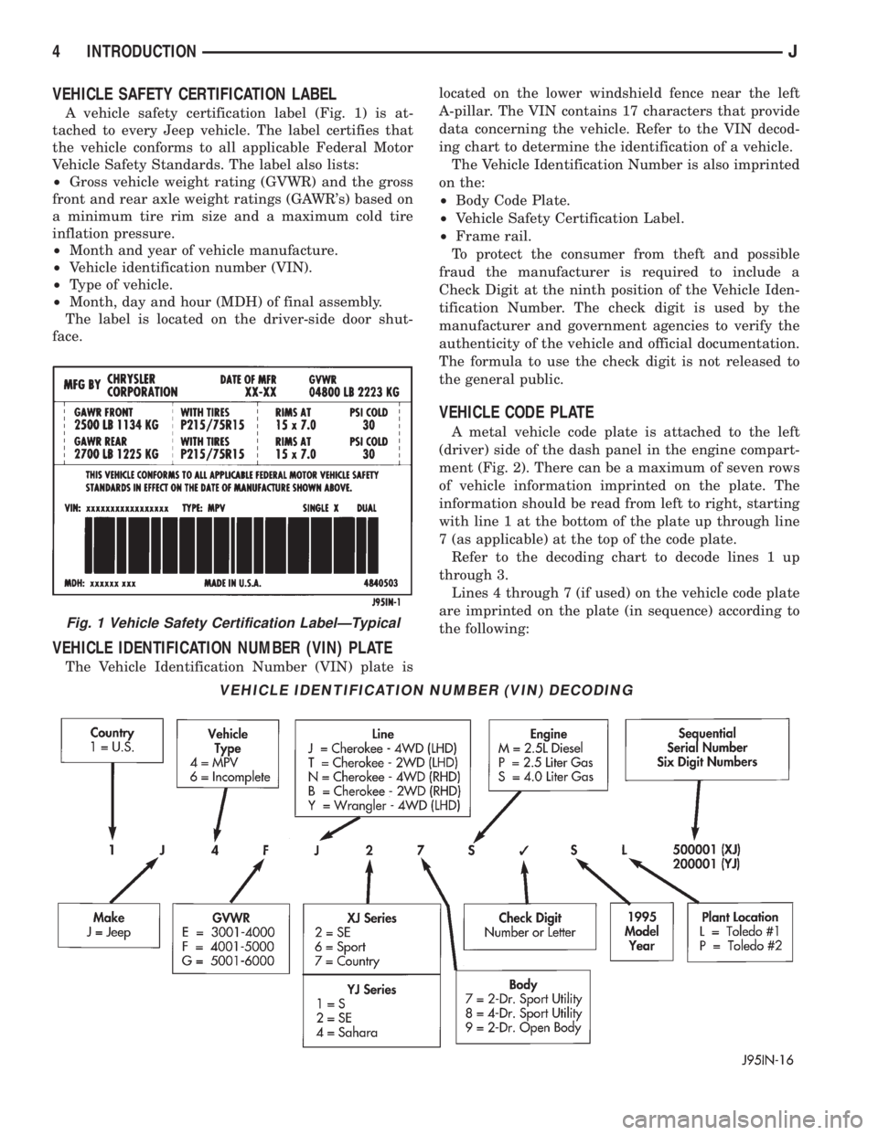
VEHICLE SAFETY CERTIFICATION LABEL
A vehicle safety certification label (Fig. 1) is at-
tached to every Jeep vehicle. The label certifies that
the vehicle conforms to all applicable Federal Motor
Vehicle Safety Standards. The label also lists:
²Gross vehicle weight rating (GVWR) and the gross
front and rear axle weight ratings (GAWR's) based on
a minimum tire rim size and a maximum cold tire
inflation pressure.
²Month and year of vehicle manufacture.
²Vehicle identification number (VIN).
²Type of vehicle.
²Month, day and hour (MDH) of final assembly.
The label is located on the driver-side door shut-
face.
VEHICLE IDENTIFICATION NUMBER (VIN) PLATE
The Vehicle Identification Number (VIN) plate islocated on the lower windshield fence near the left
A-pillar. The VIN contains 17 characters that provide
data concerning the vehicle. Refer to the VIN decod-
ing chart to determine the identification of a vehicle.
The Vehicle Identification Number is also imprinted
on the:
²Body Code Plate.
²Vehicle Safety Certification Label.
²Frame rail.
To protect the consumer from theft and possible
fraud the manufacturer is required to include a
Check Digit at the ninth position of the Vehicle Iden-
tification Number. The check digit is used by the
manufacturer and government agencies to verify the
authenticity of the vehicle and official documentation.
The formula to use the check digit is not released to
the general public.
VEHICLE CODE PLATE
A metal vehicle code plate is attached to the left
(driver) side of the dash panel in the engine compart-
ment (Fig. 2). There can be a maximum of seven rows
of vehicle information imprinted on the plate. The
information should be read from left to right, starting
with line 1 at the bottom of the plate up through line
7 (as applicable) at the top of the code plate.
Refer to the decoding chart to decode lines 1 up
through 3.
Lines 4 through 7 (if used) on the vehicle code plate
are imprinted on the plate (in sequence) according to
the following:
VEHICLE IDENTIFICATION NUMBER (VIN) DECODING
Fig. 1 Vehicle Safety Certification LabelÐTypical
4 INTRODUCTIONJ
Page 29 of 2158
CAUTION: Do not crank starter motor on disabled
vehicle for more than 15 seconds, starter will over-
heat and could fail.
(6) Allow battery in disabled vehicle to charge to at
least 12.4 volts (75%charge) before attempting to
start engine. If engine does not start within 15 sec-
onds, stop cranking engine and allow starter to cool
(15 min.), before cranking again.
DISCONNECT CABLE CLAMPS AS FOLLOWS:
²Disconnect BLACK cable clamp from engine
ground on disabled vehicle.
²When using a Booster vehicle, disconnect BLACK
cable clamp from battery negative terminal. Discon-
nect RED cable clamp from battery positive terminal.
²Disconnect RED cable clamp from battery positive
terminal on disabled vehicle.
PORTABLE STARTING UNIT
There are many types of portable starting units
available for starting engines. Follow the manufac-
turer's instructions and observe the listed precau-
tions when involved in any engine starting
procedure.
HOISTING RECOMMENDATIONS
Refer to the Owner's Manual for emergency vehicle
lifting procedures.
FLOOR JACK
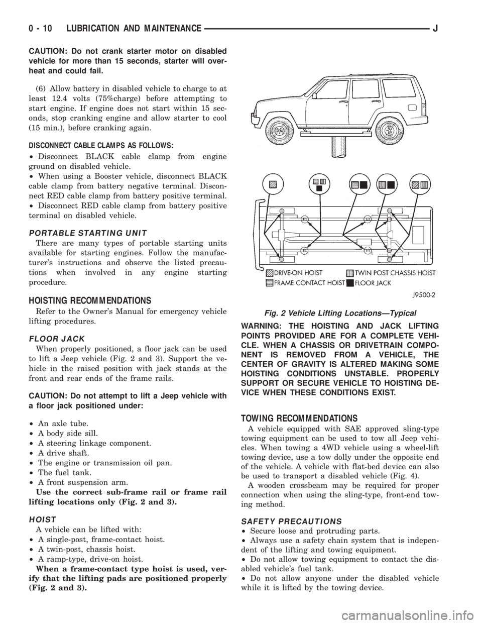
When properly positioned, a floor jack can be used
to lift a Jeep vehicle (Fig. 2 and 3). Support the ve-
hicle in the raised position with jack stands at the
front and rear ends of the frame rails.
CAUTION: Do not attempt to lift a Jeep vehicle with
a floor jack positioned under:
²An axle tube.
²A body side sill.
²A steering linkage component.
²A drive shaft.
²The engine or transmission oil pan.
²The fuel tank.
²A front suspension arm.
Use the correct sub-frame rail or frame rail
lifting locations only (Fig. 2 and 3).
HOIST
A vehicle can be lifted with:
²A single-post, frame-contact hoist.
²A twin-post, chassis hoist.
²A ramp-type, drive-on hoist.
When a frame-contact type hoist is used, ver-
ify that the lifting pads are positioned properly
(Fig. 2 and 3).WARNING: THE HOISTING AND JACK LIFTING
POINTS PROVIDED ARE FOR A COMPLETE VEHI-
CLE. WHEN A CHASSIS OR DRIVETRAIN COMPO-
NENT IS REMOVED FROM A VEHICLE, THE
CENTER OF GRAVITY IS ALTERED MAKING SOME
HOISTING CONDITIONS UNSTABLE. PROPERLY
SUPPORT OR SECURE VEHICLE TO HOISTING DE-
VICE WHEN THESE CONDITIONS EXIST.
TOWING RECOMMENDATIONS
A vehicle equipped with SAE approved sling-type
towing equipment can be used to tow all Jeep vehi-
cles. When towing a 4WD vehicle using a wheel-lift
towing device, use a tow dolly under the opposite end
of the vehicle. A vehicle with flat-bed device can also
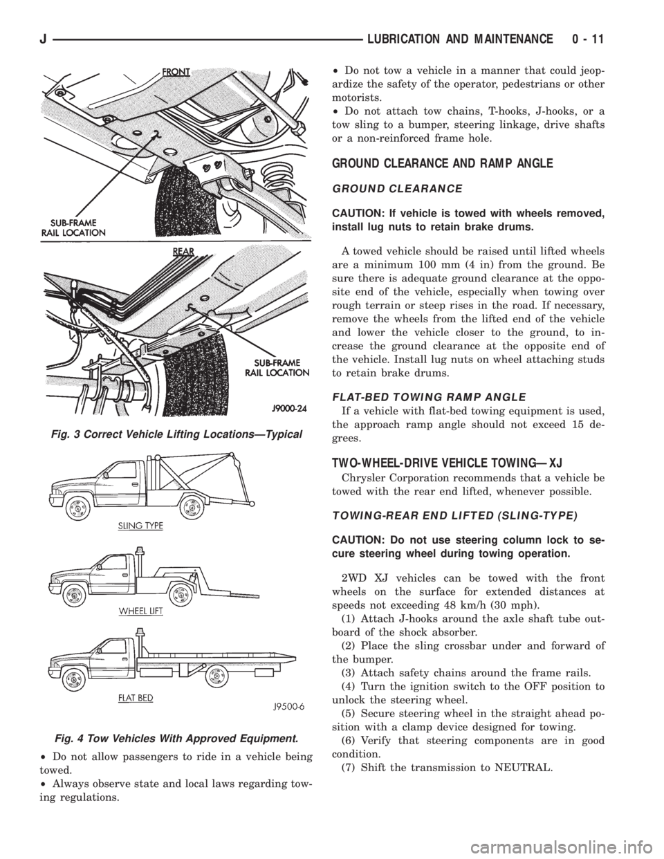
be used to transport a disabled vehicle (Fig. 4).
A wooden crossbeam may be required for proper
connection when using the sling-type, front-end tow-
ing method.
SAFETY PRECAUTIONS
²Secure loose and protruding parts.
²Always use a safety chain system that is indepen-
dent of the lifting and towing equipment.
²Do not allow towing equipment to contact the dis-
abled vehicle's fuel tank.
²Do not allow anyone under the disabled vehicle
while it is lifted by the towing device.
Fig. 2 Vehicle Lifting LocationsÐTypical
0 - 10 LUBRICATION AND MAINTENANCEJ
Page 30 of 2158
²Do not allow passengers to ride in a vehicle being
towed.
²Always observe state and local laws regarding tow-
ing regulations.²Do not tow a vehicle in a manner that could jeop-
ardize the safety of the operator, pedestrians or other
motorists.
²Do not attach tow chains, T-hooks, J-hooks, or a
tow sling to a bumper, steering linkage, drive shafts
or a non-reinforced frame hole.
GROUND CLEARANCE AND RAMP ANGLE
GROUND CLEARANCE
CAUTION: If vehicle is towed with wheels removed,
install lug nuts to retain brake drums.
A towed vehicle should be raised until lifted wheels
are a minimum 100 mm (4 in) from the ground. Be
sure there is adequate ground clearance at the oppo-
site end of the vehicle, especially when towing over
rough terrain or steep rises in the road. If necessary,
remove the wheels from the lifted end of the vehicle
and lower the vehicle closer to the ground, to in-
crease the ground clearance at the opposite end of
the vehicle. Install lug nuts on wheel attaching studs
to retain brake drums.
FLAT-BED TOWING RAMP ANGLE
If a vehicle with flat-bed towing equipment is used,
the approach ramp angle should not exceed 15 de-
grees.
TWO-WHEEL-DRIVE VEHICLE TOWINGÐXJ
Chrysler Corporation recommends that a vehicle be
towed with the rear end lifted, whenever possible.
TOWING-REAR END LIFTED (SLING-TYPE)
CAUTION: Do not use steering column lock to se-
cure steering wheel during towing operation.
2WD XJ vehicles can be towed with the front
wheels on the surface for extended distances at
speeds not exceeding 48 km/h (30 mph).
(1) Attach J-hooks around the axle shaft tube out-
board of the shock absorber.
(2) Place the sling crossbar under and forward of
the bumper.
(3) Attach safety chains around the frame rails.
(4) Turn the ignition switch to the OFF position to
unlock the steering wheel.
(5) Secure steering wheel in the straight ahead po-
sition with a clamp device designed for towing.
(6) Verify that steering components are in good
condition.
(7) Shift the transmission to NEUTRAL.
Fig. 3 Correct Vehicle Lifting LocationsÐTypical
Fig. 4 Tow Vehicles With Approved Equipment.
JLUBRICATION AND MAINTENANCE 0 - 11
Page 31 of 2158
TOWING-FRONT END LIFTED (SLING-TYPE)
CAUTION: Many vehicles are equipped with air
dams, spoilers, and/or ground effect panels. To
avoid component damage, a wheel-lift towing vehi-
cle or a flat-bed hauling vehicle is recommended.
If a 2WD XJ vehicle cannot be towed with the rear
wheels lifted, it can be towed with the front wheels
lifted.
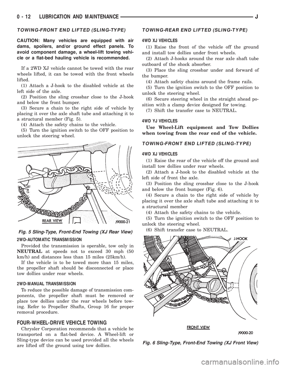
(1) Attach a J-hook to the disabled vehicle at the
left side of the axle.
(2) Position the sling crossbar close to the J-hook
and below the front bumper.
(3) Secure a chain to the right side of vehicle by
placing it over the axle shaft tube and attaching it to
a structural member (Fig. 5).
(4) Attach the safety chains to the vehicle.
(5) Turn the ignition switch to the OFF position to
unlock the steering wheel.
2WD-AUTOMATIC TRANSMISSION
Provided the transmission is operable, tow only in
NEUTRALat speeds not to exceed 30 mph (50
km/h) and distances less than 15 miles (25km/h).
If the vehicle is to be towed more than 15 miles,
the propeller shaft should be disconnected or place
tow dollies under rear wheels.
2WD-MANUAL TRANSMISSION
To reduce the possible damage of transmission com-
ponents, the propeller shaft must be removed or
place tow dollies under the rear wheels before tow-
ing. Refer to Propeller Shafts, Group 16 for proper
removal procedure.
FOUR-WHEEL-DRIVE VEHICLE TOWING
Chrysler Corporation recommends that a vehicle be
transported on a flat-bed device. A Wheel-lift or
Sling-type device can be used provided all the wheels
are lifted off the ground using tow dollies.
TOWING-REAR END LIFTED (SLING-TYPE)
4WD XJ VEHICLES
(1) Raise the front of the vehicle off the ground
and install tow dollies under front wheels.
(2) Attach J-hooks around the rear axle shaft tube
outboard of the shock absorber.
(3) Place the sling crossbar under and forward of
the bumper.
(4) Attach safety chains around the frame rails.
(5) Turn the ignition switch to the OFF position to
unlock the steering wheel.
(6) Secure steering wheel in the straight ahead po-
sition with a clamp device designed for towing.
(7) Shift the transfer case to NEUTRAL.
4WD YJ VEHICLES
Use Wheel-Lift equipment and Tow Dollies
when towing from the rear end of the vehicle.
TOWING-FRONT END LIFTED (SLING-TYPE)
4WD XJ VEHICLES
(1) Raise the rear of the vehicle off the ground and
install tow dollies under rear wheels.
(2) Attach a J-hook to the disabled vehicle at the
left side of front the axle.
(3) Position the sling crossbar close to the J-hook
and below the front bumper (Fig. 6).
(4) Secure a chain to the right side of vehicle by
placing it over the axle shaft tube and attaching it to
a structural member
(4) Attach the safety chains to the vehicle.
(5) Turn the ignition switch to the OFF position to
unlock the steering wheel.
(6) Shift transfer case to NEUTRAL.
Fig. 5 Sling-Type, Front-End Towing (XJ Rear View)
Fig. 6 Sling-Type, Front-End Towing (XJ Front View)
0 - 12 LUBRICATION AND MAINTENANCEJ
Page 32 of 2158
4WD YJ VEHICLES
(1) Raise the rear of the vehicle off the ground and
install tow dollies under rear wheels.
CAUTION: Use tow chains with T-hooks for con-
necting to the disabled vehicle's frame rails. Never
use J-hooks.
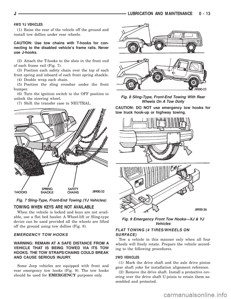
(2) Attach the T-hooks to the slots in the front end
of each frame rail (Fig. 7).
(3) Position each safety chain over the top of each
front spring and inboard of each front spring shackle.
(4) Double wrap each chain.
(5) Position the sling crossbar under the front
bumper.
(6) Turn the ignition switch to the OFF position to
unlock the steering wheel.
(7) Shift the transfer case to NEUTRAL.
TOWING WHEN KEYS ARE NOT AVAILABLE
When the vehicle is locked and keys are not avail-
able, use a flat bed hauler. A Wheel-lift or Sling-type
device can be used provided all the wheels are lifted
off the ground using tow dollies (Fig. 8).
EMERGENCY TOW HOOKS
WARNING: REMAIN AT A SAFE DISTANCE FROM A
VEHICLE THAT IS BEING TOWED VIA ITS TOW
HOOKS. THE TOW STRAPS/CHAINS COULD BREAK
AND CAUSE SERIOUS INJURY.
Some Jeep vehicles are equipped with front and
rear emergency tow hooks (Fig. 9). The tow hooks
should be used forEMERGENCYpurposes only.CAUTION: DO NOT use emergency tow hooks for
tow truck hook-up or highway towing.
FLAT TOWING (4 TIRES/WHEELS ON
SURFACE)
Tow a vehicle in this manner only when all four
wheels will freely rotate. Prepare the vehicle accord-
ing to the following procedures.
2WD VEHICLES
(1) Mark the drive shaft and the axle drive pinion
gear shaft yoke for installation alignment reference.
(2) Remove the drive shaft. Install a protective cov-
ering over the drive shaft U-joints to retain them as-
sembled and protected.
Fig. 7 Sling-Type, Front-End Towing (YJ Vehicles)
Fig. 8 Sling-Type, Front-End Towing With Rear
Wheels On A Tow Dolly
Fig. 9 Emergency Front Tow HooksÐXJ & YJ
Vehicles
JLUBRICATION AND MAINTENANCE 0 - 13
Page 40 of 2158
ENGINE SUPPORTS
The general condition of the engine supports
should be inspected when engine compartment or un-
der vehicle service is performed.
INSPECTION
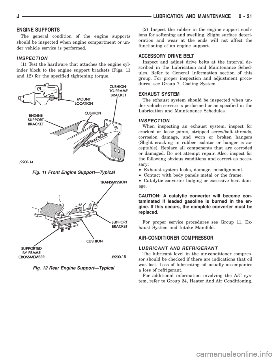
(1) Test the hardware that attaches the engine cyl-
inder block to the engine support brackets (Figs. 11
and 12) for the specified tightening torque.(2) Inspect the rubber in the engine support cush-
ions for softening and swelling. Slight surface deteri-
oration and wear at the ends will not affect the
functioning of an engine support.
ACCESSORY DRIVE BELT
Inspect and adjust drive belts at the interval de-
scribed in the Lubrication and Maintenance Sched-
ules. Refer to General Information section of this
group. For proper inspection and adjustment proce-
dures, see Group 7, Cooling System.
EXHAUST SYSTEM
The exhaust system should be inspected when un-
der vehicle service is performed or as specified in the
Lubrication and Maintenance Schedules.
INSPECTION
When inspecting an exhaust system, inspect for
cracked or loose joints, stripped screw/bolt threads,
corrosion damage, and worn or broken hangers
(Slight cracking in rubber isolator or hanger is ac-
ceptable). Replace all components that are corroded
or damaged. Do not attempt repair. Also, inspect for
the following obvious conditions and correct as neces-
sary:
²Exhaust system leaks, damage, misalignment.
²Contact with body panels metal or the frame.
²Catalytic converter bulging or excessive heat dam-
age.
CAUTION: A catalytic converter will become con-
taminated if leaded gasoline is burned in the en-
gine. If this occurs, the complete converter must be
replaced.
For proper service procedures see Group 11, Ex-
haust System and Intake Manifold.
AIR-CONDITIONER COMPRESSOR
LUBRICANT AND REFRIGERANT
The lubricant level in the air-conditioner compres-
sor should be checked if there are indications that oil
was lost. Loss of lubricating oil usually accompanies
a loss of refrigerant.
For additional information involving the A/C sys-
tem, refer to Group 24, Heater And Air Conditioning.
Fig. 11 Front Engine SupportÐTypical
Fig. 12 Rear Engine SupportÐTypical
JLUBRICATION AND MAINTENANCE 0 - 21
Page 48 of 2158
hose unless the caliper must also be removed
for maintenance.Support the caliper with a
hanger to prevent brake fluid hose damage.
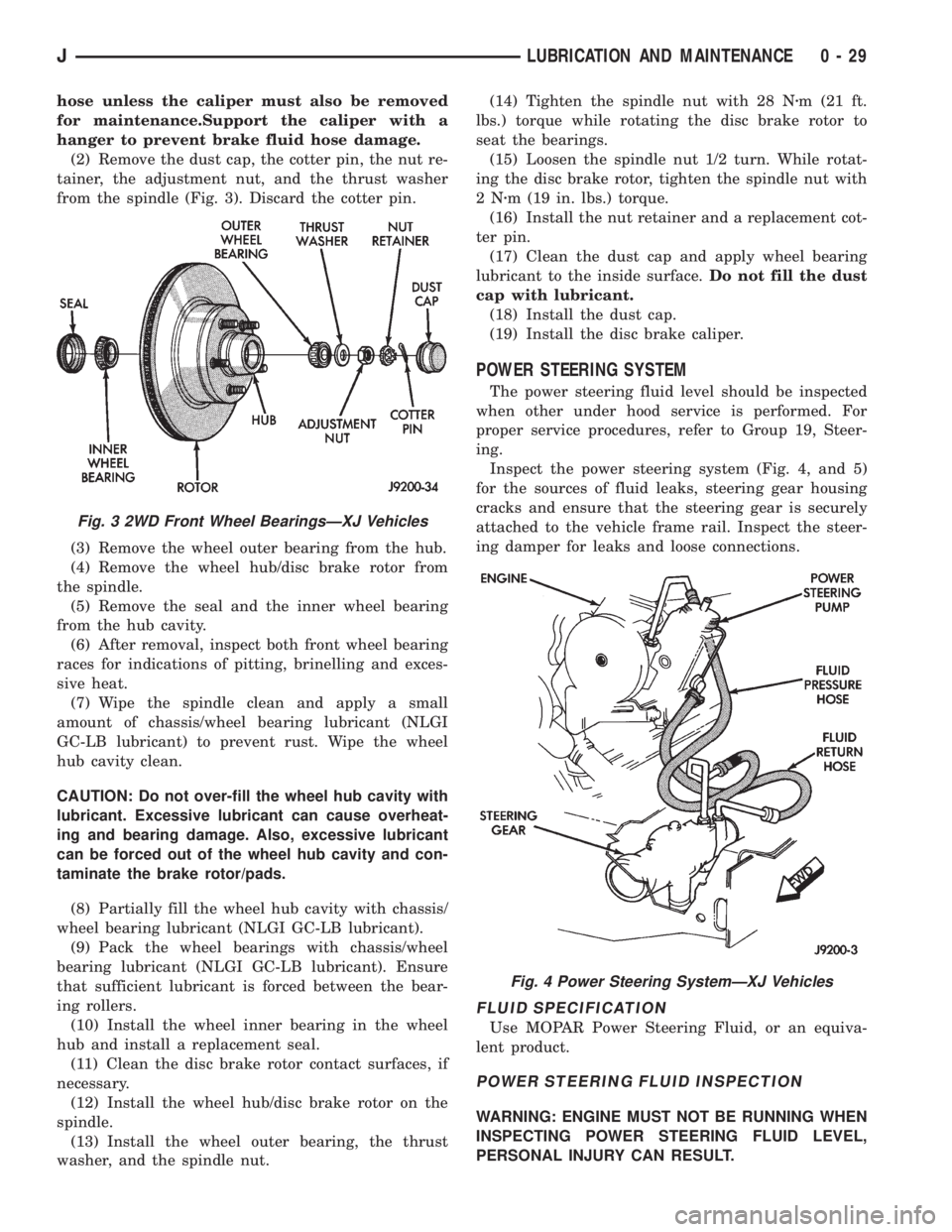
(2) Remove the dust cap, the cotter pin, the nut re-
tainer, the adjustment nut, and the thrust washer
from the spindle (Fig. 3). Discard the cotter pin.
(3) Remove the wheel outer bearing from the hub.
(4) Remove the wheel hub/disc brake rotor from
the spindle.
(5) Remove the seal and the inner wheel bearing
from the hub cavity.
(6) After removal, inspect both front wheel bearing
races for indications of pitting, brinelling and exces-
sive heat.
(7) Wipe the spindle clean and apply a small
amount of chassis/wheel bearing lubricant (NLGI
GC-LB lubricant) to prevent rust. Wipe the wheel
hub cavity clean.
CAUTION: Do not over-fill the wheel hub cavity with
lubricant. Excessive lubricant can cause overheat-
ing and bearing damage. Also, excessive lubricant
can be forced out of the wheel hub cavity and con-
taminate the brake rotor/pads.
(8) Partially fill the wheel hub cavity with chassis/
wheel bearing lubricant (NLGI GC-LB lubricant).
(9) Pack the wheel bearings with chassis/wheel
bearing lubricant (NLGI GC-LB lubricant). Ensure
that sufficient lubricant is forced between the bear-
ing rollers.
(10) Install the wheel inner bearing in the wheel
hub and install a replacement seal.
(11) Clean the disc brake rotor contact surfaces, if
necessary.
(12) Install the wheel hub/disc brake rotor on the
spindle.
(13) Install the wheel outer bearing, the thrust
washer, and the spindle nut.(14) Tighten the spindle nut with 28 Nzm (21 ft.
lbs.) torque while rotating the disc brake rotor to
seat the bearings.
(15) Loosen the spindle nut 1/2 turn. While rotat-
ing the disc brake rotor, tighten the spindle nut with
2Nzm (19 in. lbs.) torque.
(16) Install the nut retainer and a replacement cot-
ter pin.
(17) Clean the dust cap and apply wheel bearing
lubricant to the inside surface.Do not fill the dust
cap with lubricant.
(18) Install the dust cap.
(19) Install the disc brake caliper.
POWER STEERING SYSTEM
The power steering fluid level should be inspected
when other under hood service is performed. For
proper service procedures, refer to Group 19, Steer-
ing.
Inspect the power steering system (Fig. 4, and 5)
for the sources of fluid leaks, steering gear housing
cracks and ensure that the steering gear is securely
attached to the vehicle frame rail. Inspect the steer-
ing damper for leaks and loose connections.
FLUID SPECIFICATION
Use MOPAR Power Steering Fluid, or an equiva-
lent product.
POWER STEERING FLUID INSPECTION
WARNING: ENGINE MUST NOT BE RUNNING WHEN
INSPECTING POWER STEERING FLUID LEVEL,
PERSONAL INJURY CAN RESULT.
Fig. 3 2WD Front Wheel BearingsÐXJ Vehicles
Fig. 4 Power Steering SystemÐXJ Vehicles
JLUBRICATION AND MAINTENANCE 0 - 29
Page 54 of 2158
the opposite wheel. Wheels are attached to a hub/
bearings which bolts to the knuckles. The hub/bear-
ing is not serviceable and is replaced as a unit.
Steering knuckles pivot on replaceable ball studs at-
tached to the axle tube yokes.
The upper and lower suspension arms are different
lengths, with bushings at both ends. They bolt the
axle assembly to the body. The lower arms uses
shims at the body mount to allow for adjustment of
caster and drive shaft pinion angle. The suspension
arm travel is limited through the use of jounce
bumpers in compression and shocks absorbers in re-
bound.
Suspension components which use rubber bushings
should be tightened at vehicle ride height. This will
prevent premature failure of the bushing and main-
tain ride comfort. Bushings must never be lubricated.
The coil springs control ride quality and maintain
proper ride height. The coil springs mount up in the
fender shield which is part of the unitized body
bracket. A rubber isolator is located between the top
of the spring and the frame. The bottom of the spring
seats on a axle pad and is retained with a clip.
The shock absorbers dampen jounce and rebound of
the vehicle over various road conditions. The top of
the shock absorbers are bolted to the body. The bot-
tom of the shocks are bolted to the axle spring
bracket.
The stabilizer bar is used to minimize vehicle body
roll during turns. The spring steel bar helps to con-
trol the vehicle body in relationship to the suspen-
sion. The bar extends across the front underside of
the chassis and connects to the body rails. Links are
connected from the bar to the axle brackets. Stabi-
lizer bar mounts are isolated by rubber bushings.
The track bar is used to minimize front axle side-
to-side movement. The bar is attached to a frame rail
bracket with a ball stud and isolated with a bushing
at the axle bracket.
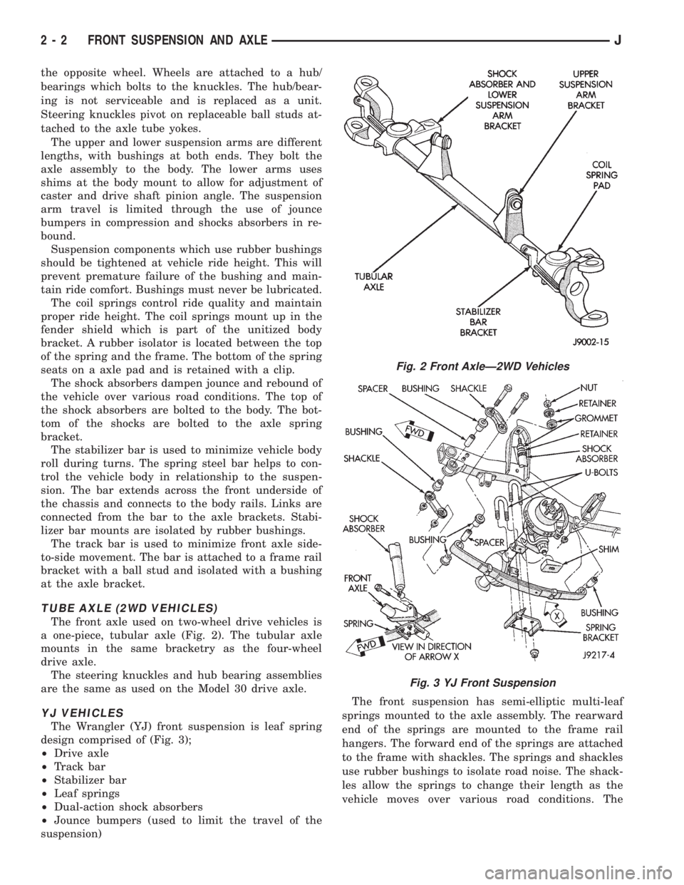
TUBE AXLE (2WD VEHICLES)
The front axle used on two-wheel drive vehicles is
a one-piece, tubular axle (Fig. 2). The tubular axle
mounts in the same bracketry as the four-wheel
drive axle.
The steering knuckles and hub bearing assemblies
are the same as used on the Model 30 drive axle.
YJ VEHICLES
The Wrangler (YJ) front suspension is leaf spring
design comprised of (Fig. 3);
²Drive axle
²Track bar
²Stabilizer bar
²Leaf springs
²Dual-action shock absorbers
²Jounce bumpers (used to limit the travel of the
suspension)The front suspension has semi-elliptic multi-leaf
springs mounted to the axle assembly. The rearward
end of the springs are mounted to the frame rail
hangers. The forward end of the springs are attached
to the frame with shackles. The springs and shackles
use rubber bushings to isolate road noise. The shack-
les allow the springs to change their length as the
vehicle moves over various road conditions. The
Fig. 2 Front AxleÐ2WD Vehicles
Fig. 3 YJ Front Suspension
2 - 2 FRONT SUSPENSION AND AXLEJ
Page 55 of 2158
spring and axle travel (jounce or rebound) is limited
through use of rubber bumpers mounted on the
frame.
Suspension components which use rubber bushings
should be tightened at vehicle ride height. This will
prevent premature failure of the bushing and main-
tain ride comfort. The bushings should never be lu-
bricated.
The shocks absorbers dampen jounce and rebound
of the vehicle over various road conditions. The top of
the shock absorbers bolt to the frame. The bottom of
the shocks bolt to the axle brackets.
The stabilizer bar is used to minimize vehicle front
sway during turns. The spring steel bar helps control
vehicle body in relationship to the suspension move-
ment. The bar extends across the front underside of
the chassis and connects to the frame rails. Links
connect the bar to the axle brackets. Stabilizer bar
mounts are isolated by rubber bushings.
The track bar is used to minimize front axle side-
to-side movement. The track bar is attached to a
frame rail bracket and axle bracket. The bar uses
bushings at both ends.
FRONT DRIVE AXLE
It is not necessary to remove the complete axle
from the vehicle for routine differential service. If the
differential housing or axle shaft tubes are damaged,
the complete axle assembly can be removed and ser-
viced.
For complete drive axle assembly removal and in-
stallation refer to Drive Axle Assembly Replacement
in this Group.
The removable cover provides for servicing without
removing axle from vehicle.
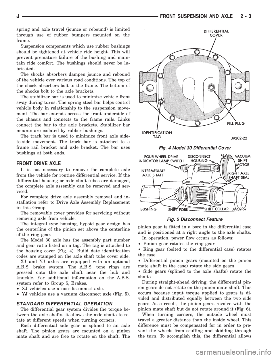
The integral type housing, hypoid gear design has
the centerline of the pinion set above the centerline
of the ring gear.
The Model 30 axle has the assembly part number
and gear ratio listed on a tag. The tag is attached to
the housing cover (Fig. 4). Build date identification
codes are stamped on the axle shaft tube cover side.
XJ and YJ axles are equipped with an optional
A.B.S. brake system. The A.B.S. tone rings are
pressed onto the axle shaft near the hub and
knuckle. For additional information on the A.B.S.
system refer to Group 5, Brakes.
²XJ vehicles use a non-disconnect axle.
²YJ vehicles use a vacuum disconnect axle (Fig. 5).
STANDARD DIFFERENTIAL OPERATION
The differential gear system divides the torque be-
tween the axle shafts. It allows the axle shafts to ro-
tate at different speeds when turning corners.
Each differential side gear is splined to an axle
shaft. The pinion gears are mounted on a pinion
mate shaft and are free to rotate on the shaft. Thepinion gear is fitted in a bore in the differential case
and is positioned at a right angle to the axle shafts.
In operation, power flow occurs as follows:
²Pinion gear rotates the ring gear
²Ring gear (bolted to the differential case) rotates
the case
²Differential pinion gears (mounted on the pinion
mate shaft in the case) rotate the side gears
²Side gears (splined to the axle shafts) rotate the
shafts
During straight-ahead driving, the differential pin-
ion gears do not rotate on the pinion mate shaft. This
occurs because input torque applied to gears is di-
vided and distributed equally between the two side
gears. As a result, the pinion gears revolve with the
pinion mate shaft but do not rotate around it (Fig. 6).
When turning corners, the outside wheel must
travel a greater distance than the inside wheel. This
difference must be compensated for in order to pre-
vent the wheels from scuffing and skidding through
the turn. To accomplish this, the differential allows
Fig. 4 Model 30 Differential Cover
Fig. 5 Disconnect Feature
JFRONT SUSPENSION AND AXLE 2 - 3