frame JEEP YJ 1995 Service And Owner's Guide
[x] Cancel search | Manufacturer: JEEP, Model Year: 1995, Model line: YJ, Model: JEEP YJ 1995Pages: 2158, PDF Size: 81.9 MB
Page 219 of 2158
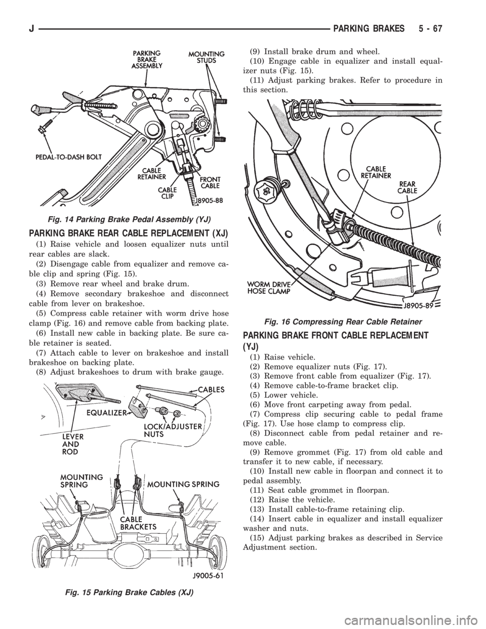
PARKING BRAKE REAR CABLE REPLACEMENT (XJ)
(1) Raise vehicle and loosen equalizer nuts until
rear cables are slack.
(2) Disengage cable from equalizer and remove ca-
ble clip and spring (Fig. 15).
(3) Remove rear wheel and brake drum.
(4) Remove secondary brakeshoe and disconnect
cable from lever on brakeshoe.
(5) Compress cable retainer with worm drive hose
clamp (Fig. 16) and remove cable from backing plate.
(6) Install new cable in backing plate. Be sure ca-
ble retainer is seated.
(7) Attach cable to lever on brakeshoe and install
brakeshoe on backing plate.
(8) Adjust brakeshoes to drum with brake gauge.(9) Install brake drum and wheel.
(10) Engage cable in equalizer and install equal-
izer nuts (Fig. 15).
(11) Adjust parking brakes. Refer to procedure in
this section.
PARKING BRAKE FRONT CABLE REPLACEMENT
(YJ)
(1) Raise vehicle.
(2) Remove equalizer nuts (Fig. 17).
(3) Remove front cable from equalizer (Fig. 17).
(4) Remove cable-to-frame bracket clip.
(5) Lower vehicle.
(6) Move front carpeting away from pedal.
(7) Compress clip securing cable to pedal frame
(Fig. 17). Use hose clamp to compress clip.
(8) Disconnect cable from pedal retainer and re-
move cable.
(9) Remove grommet (Fig. 17) from old cable and
transfer it to new cable, if necessary.
(10) Install new cable in floorpan and connect it to
pedal assembly.
(11) Seat cable grommet in floorpan.
(12) Raise the vehicle.
(13) Install cable-to-frame retaining clip.
(14) Insert cable in equalizer and install equalizer
washer and nuts.
(15) Adjust parking brakes as described in Service
Adjustment section.
Fig. 14 Parking Brake Pedal Assembly (YJ)
Fig. 15 Parking Brake Cables (XJ)
Fig. 16 Compressing Rear Cable Retainer
JPARKING BRAKES 5 - 67
Page 275 of 2158
nostic Procedures manual for diagnostic information
and operation of the DRB scan tool.
To test operation of the fan relay only, refer to Re-
laysÐOperation/Testing. This can be found in Group
14, Fuel Systems.
REMOVAL
The auxiliary cooling fan is attached to the radia-
tor upper crossmember behind the radiator.
(1) Remove the two fan mounting bolts from radi-
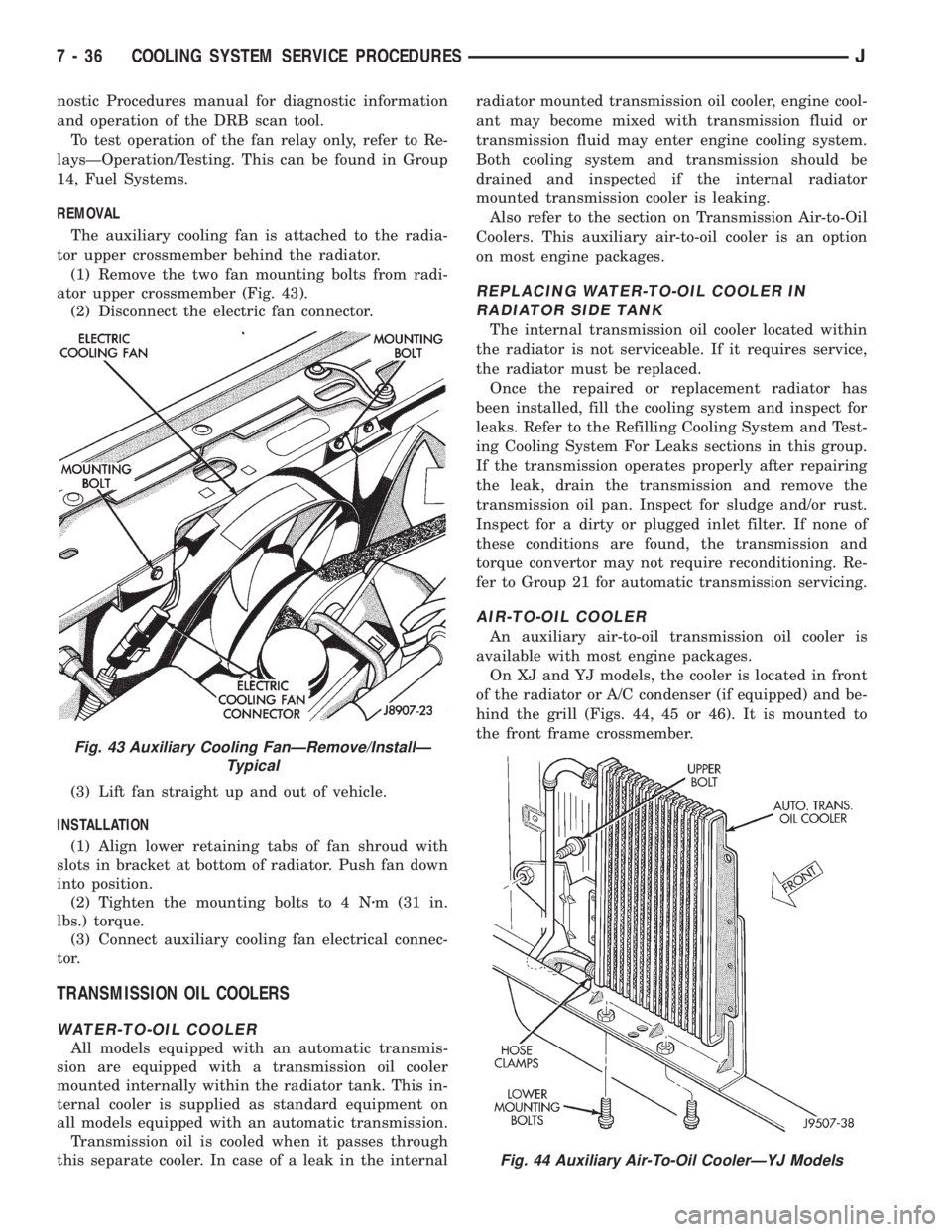
ator upper crossmember (Fig. 43).
(2) Disconnect the electric fan connector.
(3) Lift fan straight up and out of vehicle.
INSTALLATION
(1) Align lower retaining tabs of fan shroud with
slots in bracket at bottom of radiator. Push fan down
into position.
(2) Tighten the mounting bolts to 4 Nzm (31 in.
lbs.) torque.
(3) Connect auxiliary cooling fan electrical connec-
tor.
TRANSMISSION OIL COOLERS
WATER-TO-OIL COOLER
All models equipped with an automatic transmis-
sion are equipped with a transmission oil cooler
mounted internally within the radiator tank. This in-
ternal cooler is supplied as standard equipment on
all models equipped with an automatic transmission.
Transmission oil is cooled when it passes through
this separate cooler. In case of a leak in the internalradiator mounted transmission oil cooler, engine cool-
ant may become mixed with transmission fluid or
transmission fluid may enter engine cooling system.
Both cooling system and transmission should be
drained and inspected if the internal radiator
mounted transmission cooler is leaking.
Also refer to the section on Transmission Air-to-Oil
Coolers. This auxiliary air-to-oil cooler is an option
on most engine packages.
REPLACING WATER-TO-OIL COOLER IN
RADIATOR SIDE TANK
The internal transmission oil cooler located within
the radiator is not serviceable. If it requires service,
the radiator must be replaced.
Once the repaired or replacement radiator has
been installed, fill the cooling system and inspect for
leaks. Refer to the Refilling Cooling System and Test-
ing Cooling System For Leaks sections in this group.
If the transmission operates properly after repairing
the leak, drain the transmission and remove the
transmission oil pan. Inspect for sludge and/or rust.
Inspect for a dirty or plugged inlet filter. If none of
these conditions are found, the transmission and
torque convertor may not require reconditioning. Re-
fer to Group 21 for automatic transmission servicing.
AIR-TO-OIL COOLER
An auxiliary air-to-oil transmission oil cooler is
available with most engine packages.
On XJ and YJ models, the cooler is located in front
of the radiator or A/C condenser (if equipped) and be-
hind the grill (Figs. 44, 45 or 46). It is mounted to
the front frame crossmember.
Fig. 43 Auxiliary Cooling FanÐRemove/InstallÐ
Typical
Fig. 44 Auxiliary Air-To-Oil CoolerÐYJ Models
7 - 36 COOLING SYSTEM SERVICE PROCEDURESJ
Page 312 of 2158
CAUTION: Be certain that battery cables are con-
nected to the correct battery terminals. Reverse po-
larity can damage electrical components.
(12) Place oiled felt washer on battery positive ter-
minal post.
(13) Install and tighten battery positive cable ter-
minal clamp. Then install and tighten negative cableterminal clamp. Both cable clamp bolts require
torque of 8.5 Nzm (75 in. lbs.).
(14) Apply a thin coating of petroleum jelly or
chassis grease to cable terminals and battery posts.
STARTER AND STARTER RELAY
GENERAL INFORMATION
This section covers starter and starter relay service
procedures only. For diagnostic procedures, refer to
Group 8A - Battery/Starting/Charging Systems Diag-
nostics. Service procedures for other starting system
components can be found as follows:
²battery - see Battery, in this group
²ignition switch - refer to Group 8D - Ignition Sys-
tems
²park/neutral position switch (automatic transmis-
sion) - refer to Group 21 - Transmission and Transfer
Case
²wiring harness and connectors - refer to Group 8W
- Wiring Diagrams.
STARTER
The starter motor incorporates several features to
create a reliable, efficient, compact and lightweight
unit. A planetary gear system (intermediate trans-
mission) is used between the electric motor and pin-
ion gear. This feature makes it possible to reduce the
dimensions of the starter. At the same time, it allows
higher armature rotational speed and delivers in-
creased torque through the pinion gear to the fly-
wheel or drive plate ring gear.
The use of a permanent magnet field also reduces
starter size and weight. This field consists of six
high-strength permanent magnets. The magnets are
aligned according to their polarity and are perma-
nently fixed in the starter field frame.
The starter motors for all engines are activated by
a solenoid mounted to the overrunning clutch hous-
ing. However, the starter motor/solenoid are serviced
only as a complete assembly. If either component
fails, the entire assembly must be replaced.
This unit is highly sensitive to hammering, shocks
and external pressure.
CAUTION: The starter motor MUST NOT BE
CLAMPED in a vise by the starter field frame. Doing
so may damage the magnets. It may be clamped by
the mounting flange ONLY.CAUTION: Do not connect starter motor incorrectly
when tests are being performed. The permanent
magnets may be damaged and rendered unservice-
able.
STARTER RELAY
The starter relay is an International Standards Or-
ganization (ISO) type relay, and is located in the
Power Distribution Center (PDC). Refer to underside
of PDC cover for relay location.
STARTER REMOVE/INSTALLÐ2.5L
XJ MODELS
(1) Disconnect battery negative cable.
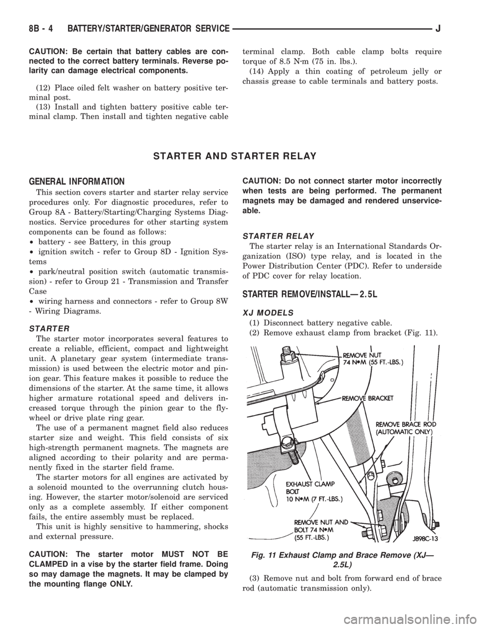
(2) Remove exhaust clamp from bracket (Fig. 11).
(3) Remove nut and bolt from forward end of brace
rod (automatic transmission only).
Fig. 11 Exhaust Clamp and Brace Remove (XJÐ
2.5L)
8B - 4 BATTERY/STARTER/GENERATOR SERVICEJ
Page 444 of 2158
GENERAL INFORMATION - YJ
Following are general descriptions of the major
components in the YJ (Wrangler) wiper and washer
systems. Refer to Group 8W - Wiring Diagrams for
complete circuit descriptions and diagrams.
WINDSHIELD WIPER SYSTEM
A two-speed wiper system is standard equipment
on all YJ models. An optional intermittent wipe sys-
tem is available. The standard system allows the
driver to select from two wiper speeds. The optional
intermittent wipe system allows the driver to select
from two wiper speeds or an intermittent wipe fea-
ture that allows a delay between wipes of 2 to 15 sec-
onds. Refer to the owner's manual for more
information on wiper system controls and operation.
The wipers will operate only when the ignition
switch is in the ACCESSORY or ON position. A cir-
cuit breaker in the fuseblock module protects the cir-
cuitry of the wiper system.
WINDSHIELD WASHER SYSTEM
A electrically-operated windshield washer system is
standard equipment on all YJ models. The washers
will operate only when the ignition switch is in the
ACCESSORY or ON position. A circuit breaker in the
fuseblock module protects the circuitry of the washer
system. Refer to the owner's manual for more infor-
mation on washer system controls and operation.
LIFTGATE WIPER/WASHER SYSTEM
A liftgate wiper/washer system is an available op-
tion on YJ models equipped with the optional hard-
top. The liftgate wiper is a fixed cycle wipe system. A
single switch on the instrument panel controls both
the liftgate wiper and washer functions. These sys-
tems will operate only when the ignition switch is in
the ON position. Fuse 1 in the fuseblock module pro-
tects the circuitry of both the liftgate wiper and
washer. Refer to the owner's manual for more infor-
mation on liftgate wiper/washer system controls and
operation.
WIPER ARMS, BLADES, AND ELEMENTS
All YJ models have two 12-inch windshield wiper
blades with replaceable rubber elements (squeegees).
Models with the liftgate wiper option use a single 16-
inch wiper blade with a replaceable rubber element
(squeegee).
Caution should be exercised to protect the rubber
squeegees from any petroleum-based cleaners or con-
taminants, which will rapidly deteriorate the squee-
gee rubber. If squeegees are damaged, worn or
contaminated they must be replaced.
Wiper squeegees exposed to the weather for a long
time tend to lose their wiping effectiveness. Periodiccleaning of the squeegees is suggested to remove de-
posits of salt and road film. The wiper blades, arms
and windshield or liftgate glass should be cleaned
with a sponge or cloth and a mild detergent or non-
abrasive cleaner. If the squeegees continue to streak
or smear, they should be replaced.
The blades are mounted to spring-loaded wiper
arms. Spring tension of the wiper arms controls the
pressure applied to the blades on the glass. The
windshield wiper arms are attached by an integral
latch to the two wiper pivots on the windshield frame
at the base of the windshield. The liftgate wiper arm
is attached by an integral latch directly to the lift-
gate wiper motor output shaft on the liftgate glass.
The wiper arms and blades can not be adjusted or re-
paired. If faulty, they must be replaced.
WIPER LINKAGE AND PIVOTS
The wiper pivots are fastened to the windshield
frame with nuts. The pivots and linkage are serviced
through access holes in the interior side of the lower
windshield frame. The two pivots and their connect-
ing link are serviced as a unit. The drive link, which
connects the motor crank arm to the left pivot, is ser-
viced separately.
WINDSHIELD WIPER MOTOR
The two-speed permanent magnet wiper motor has
an integral transmission and park switch. The motor
is mounted to a cover plate on the interior side of the
lower windshield frame. The wiper motor output
shaft passes through a gasket and the cover plate
into the space between the inner and outer lower
windshield frame, where the crank arm attached to
the output shaft drives the wiper drive link.
Wiper speed is controlled by current flow to the ap-
propriate set of brushes. The wiper motor completes
its wipe cycle when the switch is turned OFF, and
parks the blades in the lowest portion of the wipe
pattern. The wiper motor assembly can not be re-
paired. If faulty, the entire motor assembly must be
replaced. The cover plate, gasket and drive link to
crank arm retaining ring are available for service.
LIFTGATE WIPER MOTOR
The liftgate wiper motor operates in three modes:
²constant wipe that operates when the liftgate
wiper/washer switch is placed in the Wipe position
²constant wipe that operates when the liftgate
washers are operated
²a park mode that runs the motor until the wiper
blade reaches the park position after the liftgate
wiper switch or ignition switch is turned OFF.
8K - 10 WIPER AND WASHER SYSTEMS - YJJ
Page 452 of 2158
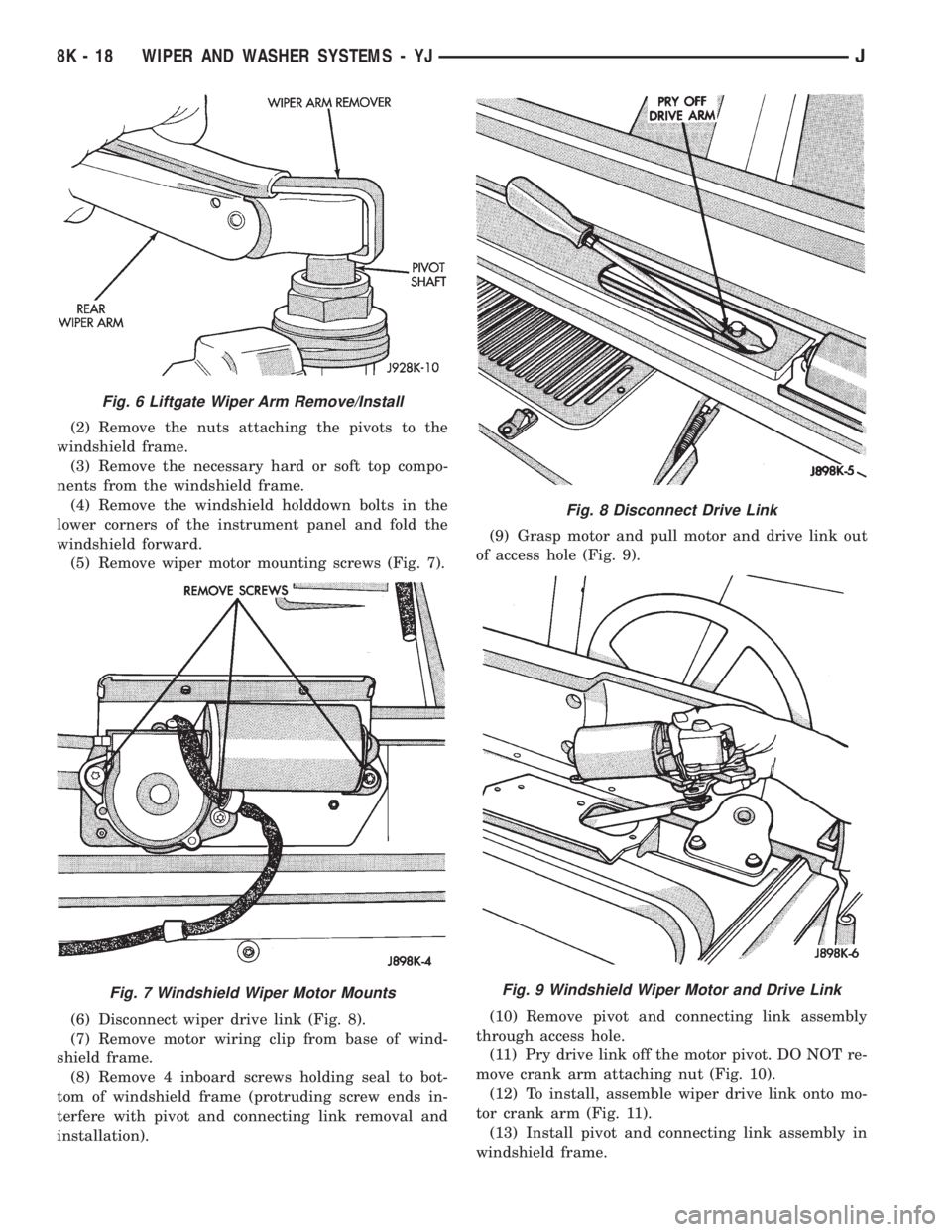
(2) Remove the nuts attaching the pivots to the
windshield frame.
(3) Remove the necessary hard or soft top compo-
nents from the windshield frame.
(4) Remove the windshield holddown bolts in the
lower corners of the instrument panel and fold the
windshield forward.
(5) Remove wiper motor mounting screws (Fig. 7).
(6) Disconnect wiper drive link (Fig. 8).
(7) Remove motor wiring clip from base of wind-
shield frame.
(8) Remove 4 inboard screws holding seal to bot-
tom of windshield frame (protruding screw ends in-
terfere with pivot and connecting link removal and
installation).(9) Grasp motor and pull motor and drive link out
of access hole (Fig. 9).
(10) Remove pivot and connecting link assembly
through access hole.
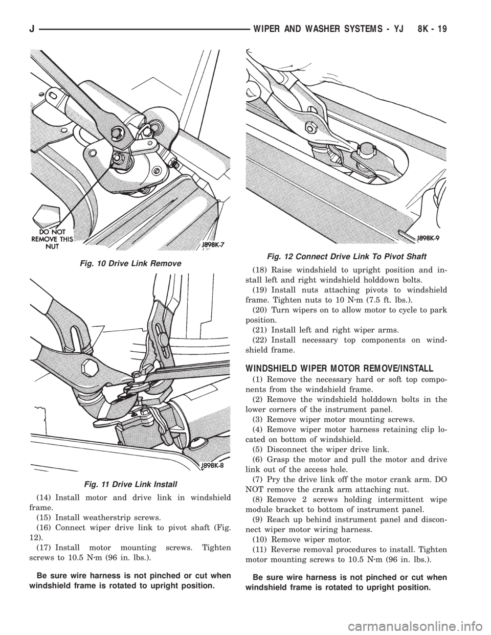
(11) Pry drive link off the motor pivot. DO NOT re-
move crank arm attaching nut (Fig. 10).
(12) To install, assemble wiper drive link onto mo-
tor crank arm (Fig. 11).
(13) Install pivot and connecting link assembly in
windshield frame.
Fig. 6 Liftgate Wiper Arm Remove/Install
Fig. 7 Windshield Wiper Motor Mounts
Fig. 8 Disconnect Drive Link
Fig. 9 Windshield Wiper Motor and Drive Link
8K - 18 WIPER AND WASHER SYSTEMS - YJJ
Page 453 of 2158
(14) Install motor and drive link in windshield
frame.
(15) Install weatherstrip screws.
(16) Connect wiper drive link to pivot shaft (Fig.
12).
(17) Install motor mounting screws. Tighten
screws to 10.5 Nzm (96 in. lbs.).
Be sure wire harness is not pinched or cut when
windshield frame is rotated to upright position.(18) Raise windshield to upright position and in-
stall left and right windshield holddown bolts.
(19) Install nuts attaching pivots to windshield
frame. Tighten nuts to 10 Nzm (7.5 ft. lbs.).
(20) Turn wipers on to allow motor to cycle to park
position.
(21) Install left and right wiper arms.
(22) Install necessary top components on wind-
shield frame.
WINDSHIELD WIPER MOTOR REMOVE/INSTALL
(1) Remove the necessary hard or soft top compo-
nents from the windshield frame.
(2) Remove the windshield holddown bolts in the
lower corners of the instrument panel.
(3) Remove wiper motor mounting screws.
(4) Remove wiper motor harness retaining clip lo-
cated on bottom of windshield.
(5) Disconnect the wiper drive link.
(6) Grasp the motor and pull the motor and drive
link out of the access hole.
(7) Pry the drive link off the motor crank arm. DO
NOT remove the crank arm attaching nut.
(8) Remove 2 screws holding intermittent wipe
module bracket to bottom of instrument panel.
(9) Reach up behind instrument panel and discon-
nect wiper motor wiring harness.
(10) Remove wiper motor.
(11) Reverse removal procedures to install. Tighten
motor mounting screws to 10.5 Nzm (96 in. lbs.).
Be sure wire harness is not pinched or cut when
windshield frame is rotated to upright position.
Fig. 10 Drive Link Remove
Fig. 11 Drive Link Install
Fig. 12 Connect Drive Link To Pivot Shaft
JWIPER AND WASHER SYSTEMS - YJ 8K - 19
Page 515 of 2158
SERVICE PROCEDURES
POWER SEAT SWITCH REMOVE/INSTALL
(1) Disconnect battery negative cable.
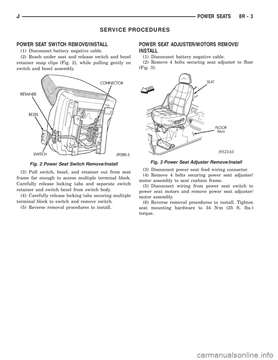
(2) Reach under seat and release switch and bezel
retainer snap clips (Fig. 2), while pulling gently on
switch and bezel assembly.
(3) Pull switch, bezel, and retainer out from seat
frame far enough to access multiple terminal block.
Carefully release locking tabs and separate switch
retainer and switch bezel from switch body.
(4) Carefully release locking tabs securing multiple
terminal block to switch and remove switch.
(5) Reverse removal procedures to install.
POWER SEAT ADJUSTER/MOTORS REMOVE/
INSTALL
(1) Disconnect battery negative cable.
(2) Remove 4 bolts securing seat adjuster to floor
(Fig. 3).
(3) Disconnect power seat feed wiring connector.
(4) Remove 4 bolts securing power seat adjuster/
motor assembly to seat cushion frame.
(5) Disconnect wiring from power seat switch to
power seat motors and remove power seat adjuster/
motor assembly.
(6) Reverse removal procedures to install. Tighten
seat mounting hardware to 34 Nzm (25 ft. lbs.)
torque.
Fig. 2 Power Seat Switch Remove/InstallFig. 3 Power Seat Adjuster Remove/Install
JPOWER SEATS 8R - 3
Page 1272 of 2158
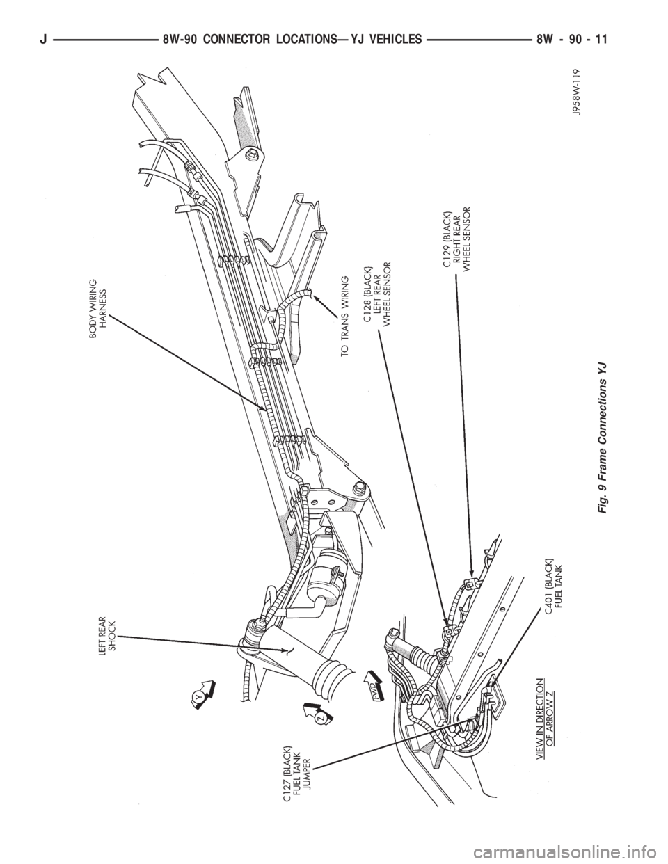
Fig. 9 Frame Connections YJ
J8W-90 CONNECTOR LOCATIONSÐYJ VEHICLES 8W - 90 - 11
Page 1299 of 2158
(a) Align the transmission torque converter hous-
ing with the engine.
(b) Loosely install the converter housing lower
bolts and install the next higher bolt and nut on
each side.
(c) Tighten all 4 bolts finger-tight.
(5) Install the engine support cushions (if re-
moved).
(6) Lower the engine and engine support cushions
onto the engine compartment brackets.
(7) Remove the engine lifting device.
(8) Raise the vehicle.
(9) If equipped with an automatic transmission:
(a) Install the converter-to-drive plate bolts. En-
sure the installation reference marks are aligned.
Tighten the bolts to 54 Nzm (40 ft. lbs.) torque.
(b) Install the converter-housing access cover.
(c) Install the exhaust pipe support.
(10) Install the remaining converter or flywheel
housing bolts.
(11) Install the starter motor and connect the ca-
ble. Tighten the bolts to 45 Nzm (33 ft. lbs.) torque.
(12) Tighten the engine support cushing through-
bolt nuts.
(13) Install the remaining flywheel and converter
housing bolts. Tighten the bolts to 38 Nzm (28 ft. lbs.)
torque.
(14) Connect the exhaust pipe to the manifold.
(15) Install the oil filter.
(16) Lower the vehicle.
(17) Connect the coolant hoses and tighten the
clamps.
(18) If equipped with power steering:
(a) Remove the protective caps
(b) Connect the hoses to the fittings at the steer-
ing gear. Tighten the nut to 52 Nzm (38 ft. lbs.)
torque.
(c) Fill the pump reservoir with fluid.
(19) Remove the pulley-to-water pump flange
alignment capscrew and install the fan and spacer or
Tempatrol fan assembly.
(20) Install the fan shroud and radiator and con-
denser (if equipped with air conditioning).
(21) Connect the radiator hoses.
(22) Connect the automatic transmission fluid
cooler pipes, if equipped.
(23) Connect the oxygen sensor wire connector.
(24) Connect the throttle valve rod and retainer.
Connect the throttle cable and install the rod. Install
the throttle valve rod spring.
(25) Connect the speed control cable, if equipped.
(26) Connect the fuel supply and return lines to
the throttle body.
(27) Connect all the vacuum hoses and wire con-
nectors.
(28) Connect the service valves to the A/C compres-
sor ports, if equipped with air conditioning.(29) Fill the power steering reservoir.
(30) Connect the battery cables.
(31) Install the hood.
(32) Install the air cleaner.
(33) Start the engine and inspect for leaks.
(34) Fill the cooling system.
(35) Stop the engine and check the fluid levels.
Add fluid, as required.
ENGINE ASSEMBLYÐYJ VEHICLES
REMOVAL
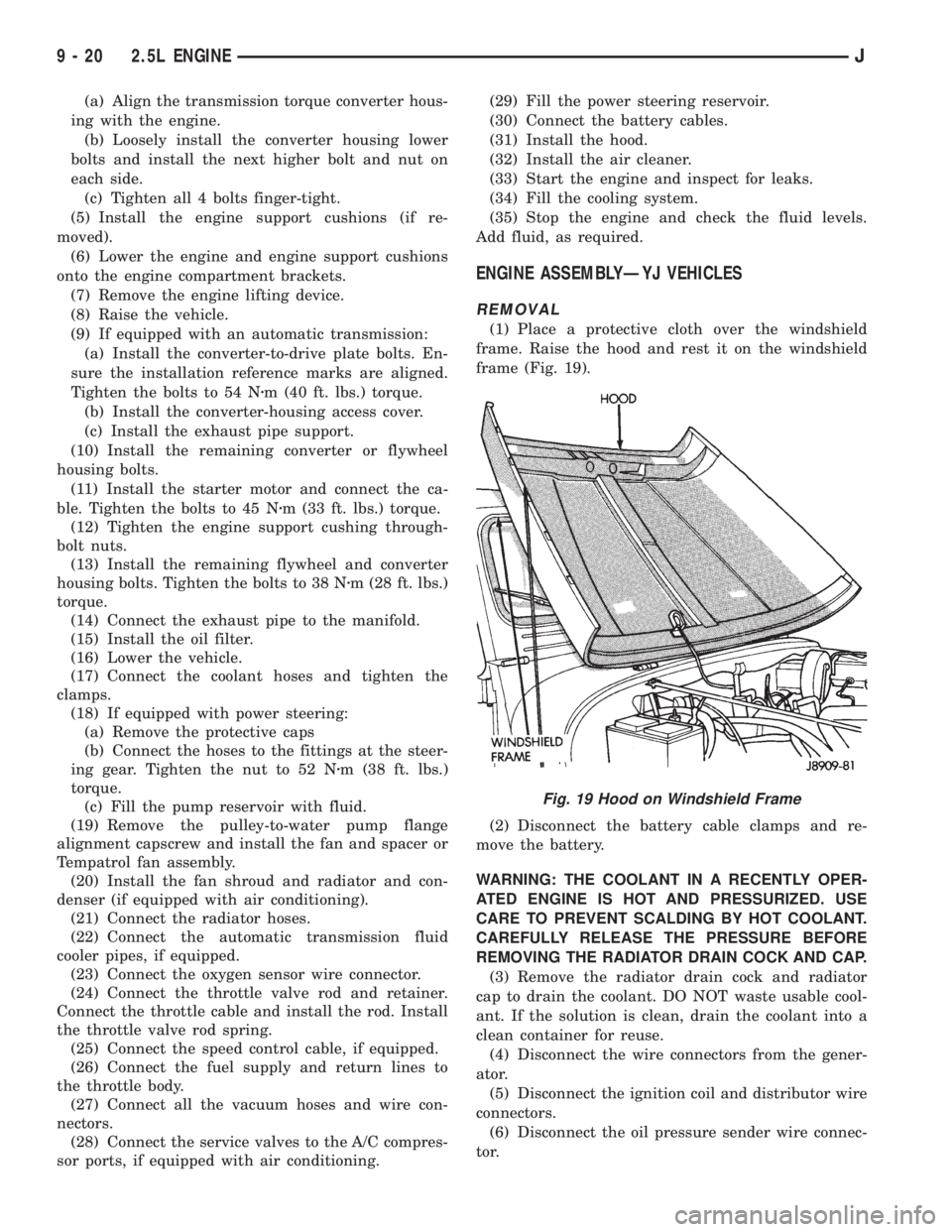
(1) Place a protective cloth over the windshield
frame. Raise the hood and rest it on the windshield
frame (Fig. 19).
(2) Disconnect the battery cable clamps and re-
move the battery.
WARNING: THE COOLANT IN A RECENTLY OPER-
ATED ENGINE IS HOT AND PRESSURIZED. USE
CARE TO PREVENT SCALDING BY HOT COOLANT.
CAREFULLY RELEASE THE PRESSURE BEFORE
REMOVING THE RADIATOR DRAIN COCK AND CAP.
(3) Remove the radiator drain cock and radiator
cap to drain the coolant. DO NOT waste usable cool-
ant. If the solution is clean, drain the coolant into a
clean container for reuse.
(4) Disconnect the wire connectors from the gener-
ator.
(5) Disconnect the ignition coil and distributor wire
connectors.
(6) Disconnect the oil pressure sender wire connec-
tor.
Fig. 19 Hood on Windshield Frame
9 - 20 2.5L ENGINEJ
Page 1341 of 2158
(26) Connect the speed control cable, if equipped.
(27) Connect the throttle cable linkages.
(28) Connect the heater hoses at the engine ther-
mostat housing and water pump.
(29) Install the fan assembly to the idler pulley.
(30) Install the radiator or radiator and condenser
(if equipped with A/C).
(31) Connect the service valves to the A/C compres-
sor ports, if equipped with A/C.
(32) Charge the air conditioner system.
(33) Connect radiator fan switch wire.
(34) Connect automatic transmission fluid cooler
lines, if equipped.
(35) Install the fan shroud, electric cooling fan and
radiator and condenser (if equipped with A/C).
(36) Install upper radiator support.
(37) Connect the upper radiator hose.
(38) Connect the lower radiator hose.
(39) Fill the cooling system with reusable coolant
and/or new coolant.
(40) Align the hood to the scribe marks. Install the
hood.
(41) Connect the vacuum harness connector.
(a) Firmly push the connectors together ensuring
that the retaining tabs are engaged.
(b) Insert the vacuum connector assembly into
the retaining bracket on the intake manifold.
(42) Install the air cleaner assembly.
(43) Install the battery and connect the battery ca-
ble.
WARNING: USE EXTREME CAUTION WHEN THE
ENGINE IS OPERATING. DO NOT STAND IN A DI-
RECT LINE WITH THE FAN. DO NOT PUT YOUR
HANDS NEAR THE PULLEYS, BELTS OR FAN. DO
NOT WEAR LOOSE CLOTHING.
(44) Start the engine, inspect for leaks and correct
the fluid levels, as necessary.
ENGINE ASSEMBLYÐYJ VEHICLES
REMOVAL
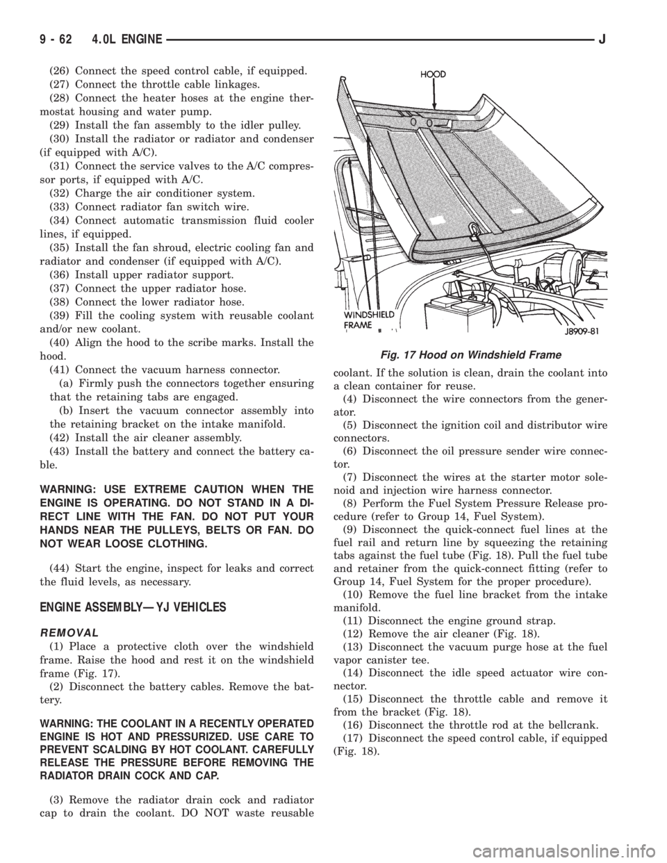
(1) Place a protective cloth over the windshield
frame. Raise the hood and rest it on the windshield
frame (Fig. 17).
(2) Disconnect the battery cables. Remove the bat-
tery.
WARNING: THE COOLANT IN A RECENTLY OPERATED
ENGINE IS HOT AND PRESSURIZED. USE CARE TO
PREVENT SCALDING BY HOT COOLANT. CAREFULLY
RELEASE THE PRESSURE BEFORE REMOVING THE
RADIATOR DRAIN COCK AND CAP.
(3) Remove the radiator drain cock and radiator
cap to drain the coolant. DO NOT waste reusablecoolant. If the solution is clean, drain the coolant into
a clean container for reuse.
(4) Disconnect the wire connectors from the gener-
ator.
(5) Disconnect the ignition coil and distributor wire
connectors.
(6) Disconnect the oil pressure sender wire connec-
tor.
(7) Disconnect the wires at the starter motor sole-
noid and injection wire harness connector.
(8) Perform the Fuel System Pressure Release pro-
cedure (refer to Group 14, Fuel System).
(9) Disconnect the quick-connect fuel lines at the
fuel rail and return line by squeezing the retaining
tabs against the fuel tube (Fig. 18). Pull the fuel tube
and retainer from the quick-connect fitting (refer to
Group 14, Fuel System for the proper procedure).
(10) Remove the fuel line bracket from the intake
manifold.
(11) Disconnect the engine ground strap.
(12) Remove the air cleaner (Fig. 18).
(13) Disconnect the vacuum purge hose at the fuel
vapor canister tee.
(14) Disconnect the idle speed actuator wire con-
nector.
(15) Disconnect the throttle cable and remove it
from the bracket (Fig. 18).
(16) Disconnect the throttle rod at the bellcrank.
(17) Disconnect the speed control cable, if equipped
(Fig. 18).
Fig. 17 Hood on Windshield Frame
9 - 62 4.0L ENGINEJ