reverse KIA CARNIVAL 2007 Repair Manual
[x] Cancel search | Manufacturer: KIA, Model Year: 2007, Model line: CARNIVAL, Model: KIA CARNIVAL 2007Pages: 1575, PDF Size: 44.86 MB
Page 685 of 1575

2007 > 2.7L V6 GASOLINE >
INSPECTION
1.Ignition "ON"
2. Blow air with changing temperature to the in car sensor air inlet. Measure sensor resistance between 2 and 4
terminals.
Specification
Temperature [°C(°F)] Resistance between terminals 2and 4 (kΩ)
0 (32) 97.83 ± 2.61%
15 (59) 47.12 ± 1.45%
25 (77) 30.00 ± 1.20%
35 (95) 19.60 ± 1.44%
50 (122) 10.82 ± 2.26%
In car sensor is negative type thermistor that resistance will rise with lower temperature, and reduce with
higher temperature.
REPLACEMENT
1.Disconnect the negative ( - ) battery terminal.
2. Remove the A/C control pannel. (Refer to BD group).
3. Disconnect the connector of in - car sensor (A).Loosen the mounting 2 screws and then remove the in - car sensor
(B).
4.Installation is the reverse order of removal.
Page 689 of 1575
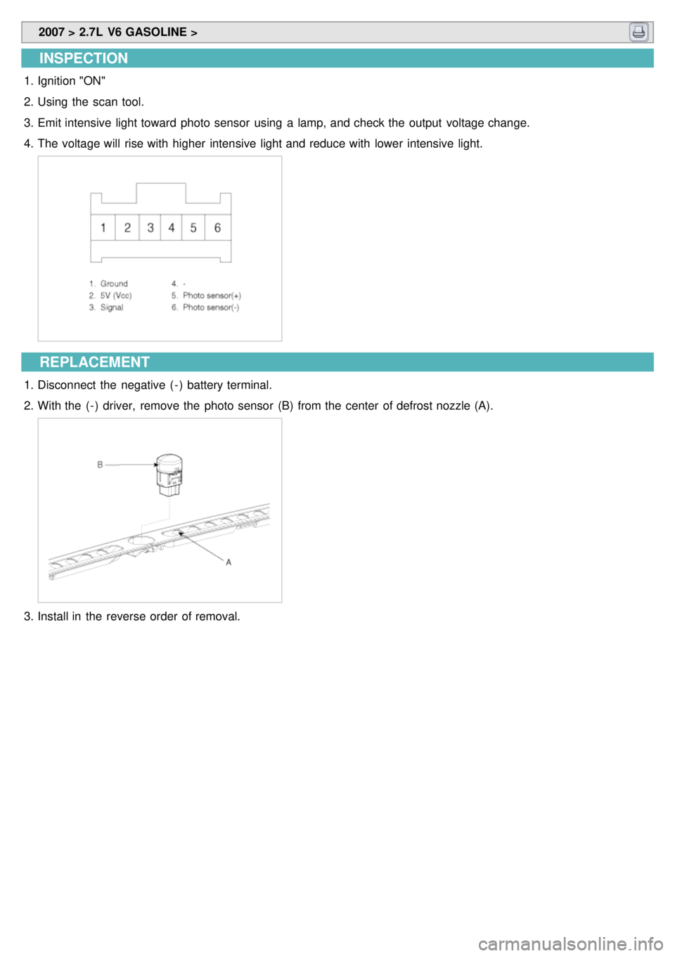
2007 > 2.7L V6 GASOLINE >
INSPECTION
1.Ignition "ON"
2. Using the scan tool.
3. Emit intensive light toward photo sensor using a lamp, and check the output voltage change.
4. The voltage will rise with higher intensive light and reduce with lower intensive light.
REPLACEMENT
1.Disconnect the negative ( - ) battery terminal.
2. With the ( - ) driver, remove the photo sensor (B) from the center of defrost nozzle (A).
3.Install in the reverse order of removal.
Page 694 of 1575

4.Installation is the reverse order of removal.
Take care that wire of water temperature sensor is not to be damaged
Page 698 of 1575

2007 > 2.7L V6 GASOLINE >
INSPECTION
1.Ignition "OFF"
2. Disconnect ambient temperature sensor.
3. Check the resistance of ambient temperature sensor between terminals 1 and 2 whether it is changed by changing
of the ambient temperature.
Specification
Ambient temperature [°C(°F)] Resistance between terminals 1and 2 (kΩ)
- 10(14) 164 ± 3%
0 (32) 97.5 ± 3%
10 (50) 59.6 ± 3%
20 (68) 37.5 ± 3%
4.If the measured resistance is not specification, substitute with a known- good ambient temperature sensor and
check for proper operation.
5. If the problem is corrected, replace the ambient temperature sensor.
REPLACEMENT
1.Disconnect the negative ( - ) battery terminal.
2. Remove the front bumper. (Refer to BD group)
3. Remove the ambient temperature sensor (A).
4.Installation is the reverse order of removal.
Page 702 of 1575
2007 > 2.7L V6 GASOLINE >
INSPECTION
1.Ignition "ON"
2. Using the scan tool.
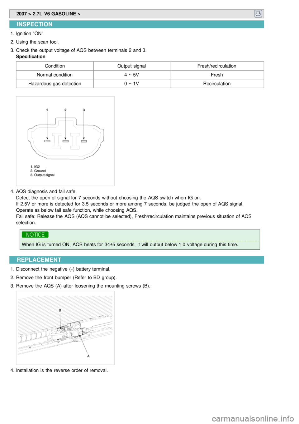
3. Check the output voltage of AQS between terminals 2 and 3.
Specification
Condition Output signal Fresh/recirculation
Normal condition 4 ~ 5VFresh
Hazardous gas detection 0 ~ 1VRecirculation
4.AQS diagnosis and fail safe
Detect the open of signal for 7 seconds without choosing the AQS switch when IG on.
If 2.5V or more is detected for 3.5 seconds or more among 7 seconds, be judged the open of AQS signal.
Operate as below fail safe function, while choosing AQS.
Fail safe: Release the AQS (AQS cannot be selected), Fresh/recirculation maintains previous situation of AQS
selection.
When IG is turned ON, AQS heats for 34±5 seconds, it will output below 1.0 voltage during this time.
REPLACEMENT
1.Disconnect the negative ( - ) battery terminal.
2. Remove the front bumper (Refer to BD group).
3. Remove the AQS (A) after loosening the mounting screws (B).
4.Installation is the reverse order of removal.
Page 706 of 1575

2007 > 2.7L V6 GASOLINE >
INSPECTION
1.Ignition "ON"
2. Using the scan tool.
3. Check the frequency of humidity sensor between terminals 2 and 3.
Humidity (%) Frequency between terminals 2and 3 (Hz)
30 6976 ± 5%
50 6728 ± 5%
60 6600 ± 5%
70 6468 ± 5%
80 6330 ± 5%
90 6186 ± 5%
4. If the measured resistance is not specification, substitute with a known- good humidity sensor and check for proper
operation.
5. If the problem is corrected, replace the Humidity sensor.
REPLACEMENT
1.Disconnect the negative ( - ) battery terminal.
2. Remove the center facia lower panel (A). (Refer to BD group)
3. Disconnect the humidity sensor connector (A).
4. Loosen 2 screws and then remove the humidity sensor (B).
5.Installation is the reverse order of removal.
Page 715 of 1575

14.Remove the evaporator core(A).
15.Be careful that the inlet and outlet pipe are not bent during heater core removal, and pull out the heater core.
16. Install the heater core in the reverse order of removal.
17. Installation is the reverse order of removal, and note these items :
a. If you're installing a new evaporator, add refrigerant oil (ND - OIL8).
b. Replace the O - rings with new ones at each fitting, and apply a thin coat of refrigerant oil before installing
them. Be sure to use the right O - rings for R- 134a to avoid leakage.
c. Immediately after using the oil, replace the cap on the container, and seal it to avoid moisture absorption.
d. Do not spill the refrigerant oil on the vehicle ; it may damage the paint ; if the refrigerant oil contacts the paint,
wash it off immediately
e. Apply sealant to the grommets.
f. Make sure that there is no air leakage.
g. Charge the system and test its performance.
h. Do not interchange the inlet and outlet heater hoses and install the hose clamps securely.
i. Refill the cooling system with engine coolant.
Page 719 of 1575

2007 > 2.7L V6 GASOLINE >
INSPECTION
1.Ignition "OFF"
2. Disconnect the connector of temperature control actuator.
3. Verify that the temperature control actuator operates to the hot position when connecting 12V to the terminal 1 and
grounding terminal 2.
Verify that the temperature control actuator operates to the cool position when connecting in the reverse.
[PASSENGER]
Specification
Door position Voltage (3- 4)Error detecting
Max. cooling 0.4 ± 0.15VLow voltage : 0.1V or less
Max. heating 4.6 ± 0.15VHigh voltage :4.9V or more
[DRIVER]
Specification
Door position Voltage (4- 5)Error detecting
Max. cooling 0.4 ± 0.15VLow voltage : 0.1V or less
Max. heating 4.6 ± 0.15VHigh voltage :4.9V or more
It will feedback current position of actuator to controls.
4. If the measured voltage is not specification, substitute with a known- good temperature control actuator and check
for proper operation.
5. If the problem is corrected, replace the temperature control actuator.
REPLACEMENT
Page 720 of 1575

1.Disconnect the negative ( - ) battery terminal.
2. Remove the driver’s crush pad lower panel (Refer to BD group).
3. Disconnect the temperature control actuator connector (A) after removing the air duct.
4. Loosen the mounting screw and then remove the temperature control actuator (B).
[Passenger's]
[Driver's]
5.Installation is the reverse order of removal.
Page 724 of 1575

2007 > 2.7L V6 GASOLINE >
INSPECTION
1.Ignition "OFF"
2. Disconnect the connector of mode control actuator.
3. Verify that the mode control actuator operates to the defrost mode when connecting 12V to the terminal 1 and
grounding terminal 2.
4. Verify that the mode control actuator operates to the vent mode when connecting in the reverse.
[DRIVER]
[PASSENGER]
5.Check the voltage between terminals 3 and 4.
Door position Voltage (3- 4)Error detecting
Vent 0.4 ± 0.15VLow voltage :0.1V or less
Defrost 4.6 ± 0.15VHigh voltage :4.9V or more
It will feedback current position of actuator to controls.
6. If the measured voltage is not specification, substitute with a known- good mode control actuator and check for
proper operation.
7. If the problem is corrected, replace the mode control actuator.
REPLACEMENT
1.Disconnect the negative ( - ) battery terminal.
2. Remove the driver’s crush pad lower panel (Refer to BD group).
3. Disconnect the temperature control actuator connector (A) after removing the air duct.
4. Loosen the mounting screw and then remove the temperature control actuator (B).