reverse KIA CARNIVAL 2007 Owner's Guide
[x] Cancel search | Manufacturer: KIA, Model Year: 2007, Model line: CARNIVAL, Model: KIA CARNIVAL 2007Pages: 1575, PDF Size: 44.86 MB
Page 394 of 1575

2007 > 2.7L V6 GASOLINE >
DESCRIPTION
Actuators
Solenoid Valve for Pressure Control
- Sensor type: Normal open 3 - way
- Operating temperature : - 30°C~130°C( - 22°F~266°F)
- Frequency:
LR, 2ND, UD, OD: 61.27Hz (at the ATF temp. above - 20°C(- 4°F))
DCC: 30.64Hz
- Internal resistance:
3.0 ± 0.5 Ω (LR, 2ND, UD, OD, TCC)
4.35 ± 0.5 Ω (VFS)
- Surge voltage: 56 V (Except VFS)
(LR, 2ND, UD, OD, DCC)
Location
Solenoid Valves Schedule
Position Solenoid valves
Operation LR2ND UDOD* DCC
1st gear OFFONOFF ONOFF
2nd gear ONOFF OFF ONOFF
3rd gear ONONOFF OFF ON
4th gear ONOFF ONOFF ON
Reverse OFFONONONOFF
N, P (STD. mode) OFFONONONOFF
N, P (Hold mode) ONOFF ONONOFF
*: Reference value.
(DCC solenoid valve will be ON when the operating condition is satisfied)
Page 405 of 1575

2007 > 2.7L V6 GASOLINE >
REPLACEMENT
1.Remove the battery and air cleaner (see "Transaxle range switch replacement").
2. Remove the transaxle range switch connector.
3. Remove the control cable to transaxle range switch mounting nut.
4. Remove the input shaft speed sensor(A).
(1) Disconnect the input shaft speed sensor connector.
(2) Remove the bolt(B).
(3)Inspect the input shaft speed sensor bore.
5. Apply a light coat of automatic transaxle fluid to the O - ring seal before installation.
6. Install the input shaft speed sensor.
7. Install the control cable mounting bracket.
8. Connect the input shaft speed sensor connector.
9. Install the holder of the control cable.
10. Adjust the control cable to transaxle range switch and tighten the transaxle manual lever to the control cable
mounting nut. (see "Automatic transaxle shift control installation")
11. Installation is the reverse of removal.
Page 409 of 1575
2007 > 2.7L V6 GASOLINE >
REPLACEMENT
1.Remove the battery and air cleaner. (see "Transaxle range switch replacement")
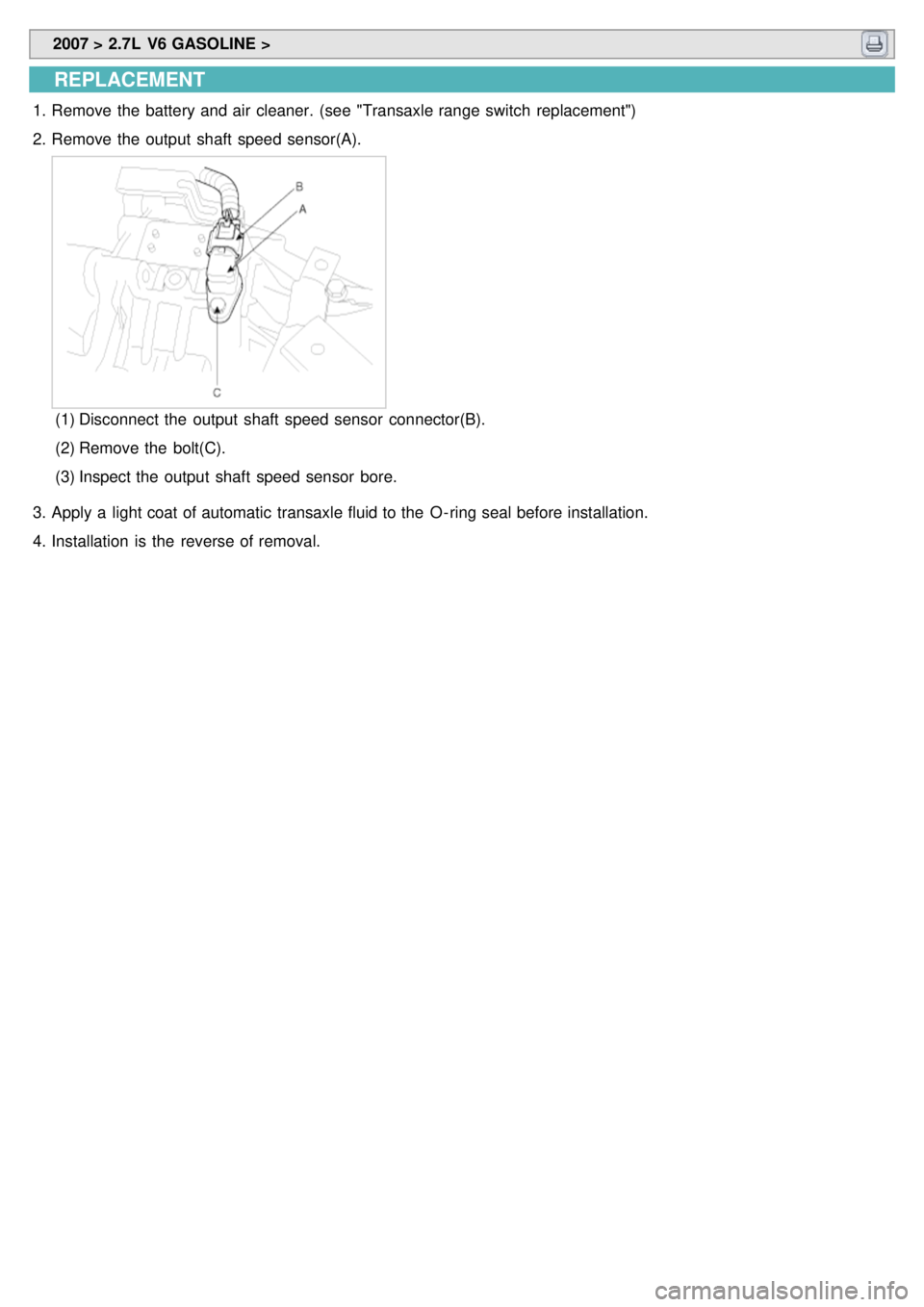
2. Remove the output shaft speed sensor(A).
(1) Disconnect the output shaft speed sensor connector(B).
(2) Remove the bolt(C).
(3) Inspect the output shaft speed sensor bore.
3. Apply a light coat of automatic transaxle fluid to the O - ring seal before installation.
4. Installation is the reverse of removal.
Page 421 of 1575
2007 > 2.7L V6 GASOLINE >
SPECIFICATION
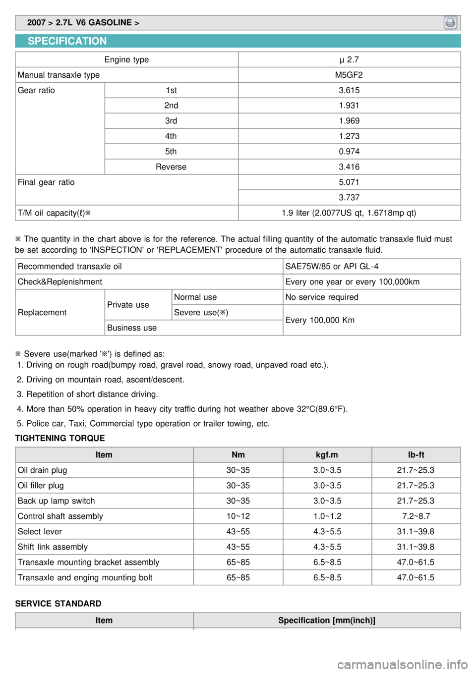
Engine type µ 2.7
Manual transaxle type M5GF2
Gear ratio 1st 3.615
2nd 1.931
3rd 1.969
4th 1.273
5th 0.974
Reverse 3.416
Final gear ratio 5.071
3.737
T/M oil capacity(ℓ) ※ 1.9 liter (2.0077US qt, 1.6718mp qt)
※ The quantity in the chart above is for the reference. The actual filling quantity of the automatic transaxle fluid must
be set according to 'INSPECTION' or 'REPLACEMENT' procedure of the automatic transaxle fluid.
Recommended transaxle oil SAE75W/85 or API GL - 4
Check&Replenishment Every one year or every 100,000km
Replacement Private useNormal use
No service required
Severe use( ※)
Every 100,000 Km
Business use
※ Severe use(marked '※') is defined as:
1. Driving on rough road(bumpy road, gravel road, snowy road, unpaved road etc.).
2. Driving on mountain road, ascent/descent.
3. Repetition of short distance driving.
4. More than 50% operation in heavy city traffic during hot weather above 32°C(89.6°F).
5. Police car, Taxi, Commercial type operation or trailer towing, etc.
TIGHTENING TORQUE
Item Nmkgf.m lb- ft
Oil drain plug 30~353.0~3.521.7~25.3
Oil filler plug 30~353.0~3.521.7~25.3
Back up lamp switch 30~353.0~3.521.7~25.3
Control shaft assembly 10~121.0~1.2 7.2~8.7
Select lever 43~554.3~5.531.1~39.8
Shift link assembly 43~554.3~5.531.1~39.8
Transaxle mounting bracket assembly 65~856.5~8.547.0~61.5
Transaxle and enging mounting bolt 65~856.5~8.547.0~61.5
SERVICE STANDARD Item Specification [mm(inch)]
Page 422 of 1575
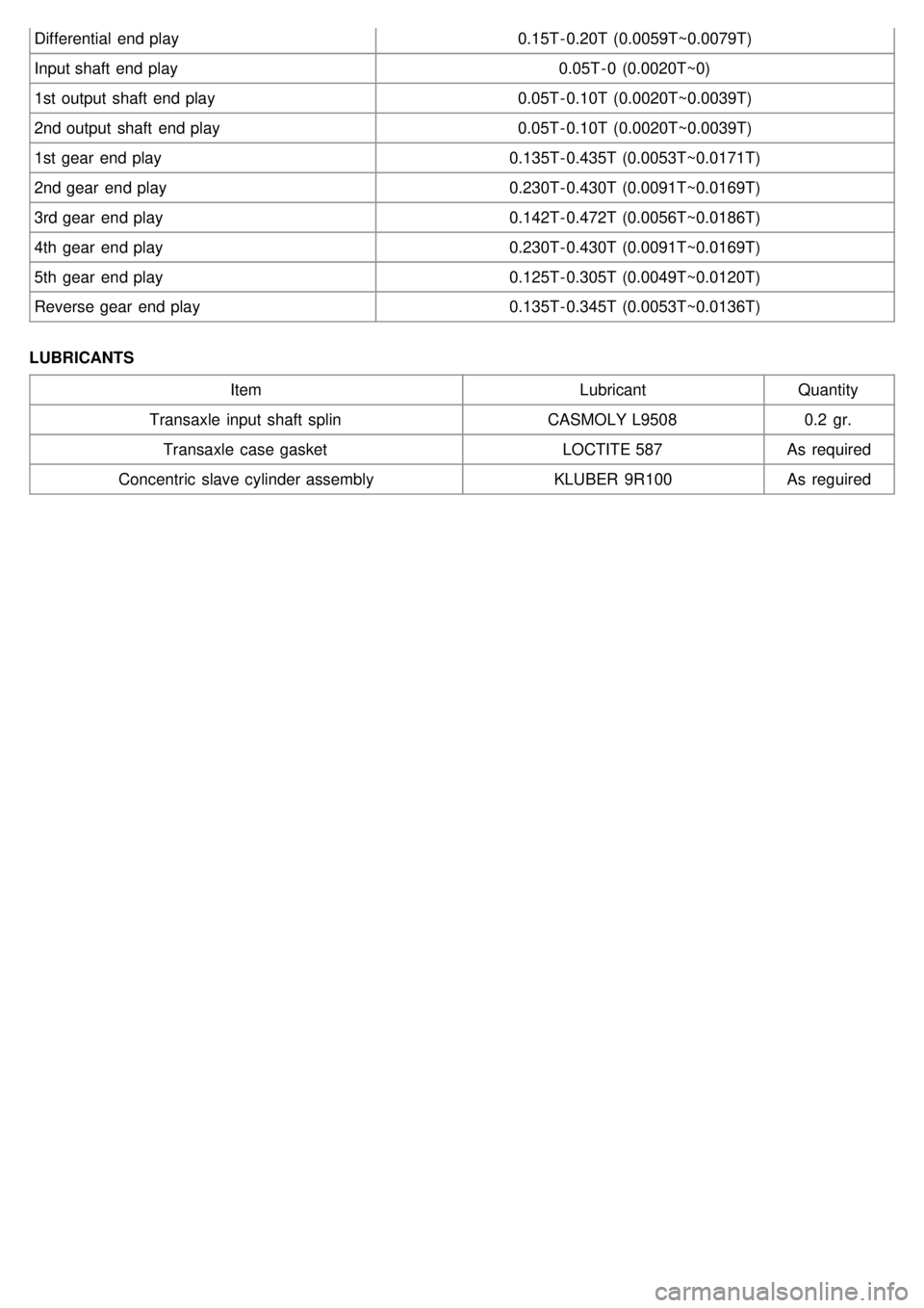
Differential end play0.15T - 0.20T (0.0059T~0.0079T)
Input shaft end play 0.05T - 0 (0.0020T~0)
1st output shaft end play 0.05T - 0.10T (0.0020T~0.0039T)
2nd output shaft end play 0.05T - 0.10T (0.0020T~0.0039T)
1st gear end play 0.135T- 0.435T (0.0053T~0.0171T)
2nd gear end play 0.230T- 0.430T (0.0091T~0.0169T)
3rd gear end play 0.142T- 0.472T (0.0056T~0.0186T)
4th gear end play 0.230T- 0.430T (0.0091T~0.0169T)
5th gear end play 0.125T- 0.305T (0.0049T~0.0120T)
Reverse gear end play 0.135T- 0.345T (0.0053T~0.0136T)
LUBRICANTS Item LubricantQuantity
Transaxle input shaft splin CASMOLY L95080.2 gr.
Transaxle case gasket LOCTITE 587As required
Concentric slave cylinder assembly KLUBER 9R100As reguired
Page 424 of 1575

2007 > 2.7L V6 GASOLINE >
SERVICE ADJUSTMENT PROCEDURE
Transmission oil inspection and replacement
1. After parking the vehicle on a plain, stop the engine.
2. After removing the oil filler plug and washer, inspect the manual transaxle fluid condition and quantity.
3. If the manual transaxle fluid is contaminated, drain it out by removing the oil drain plug.
4. Tighten the new oil drain plug and feed manual transaxle fluid to a proper level.
TORQUE:
29.4~34.4 Nm(3.0~3.5kgf.m, 21.7~25.3lb - ft)
Oil type: SAE75W/85
Oil quantity:
1.9 liter(2.0077 US qt, 1.6718 lmp qt)
5. Retighten the oil filler plug with a new washer.
TORQUE:
29.4~34.4 Nm(3.0~3.5kgf.m, 21.7~25.3lb - ft)
Back up lamp switch inspection
1.Disconnect the back up lamp switch connector(B).
2.Inspect the continuity of the switch. When the shift lever is located in reverse range, it should be applied an electric
current.
3. Replace the back up lamp switch, if necessary.
TORQUE:
29.4~34.4 Nm(3.0~3.5kgf.m, 21.7~25.3lb - ft)
Page 456 of 1575

1.Installation is reverse of the removal.
a.The driveshaft lock nut should be replaced with new ones.
b. After installation driveshaft lock nut, stake the lock nut using a chisel and hammer as shown in the
illustration below.
INSPECTION
1.Check the driveshaft boots for damage and deterioration.
2. Check the ball joints for wear and damage.
3. Check the splines for wear and damage.
4. Check the dynamic damper for cracks and wear.
Page 473 of 1575

Tightening torque Nm (kgf.m, lb - ft):
100 ~ 120 (10.0 ~12.0, 72 ~ 87)
INSTALLATION
1.Installation is reverse of the removal.
a.The driveshaft lock nut should be replaced with new ones.
b. After installation driveshaft lock nut, stake the lock nut using a chisel and hammer as shown in the
illustration below.
DISASSEMBLY
1.Separate the hub & bearing assembly (A) from the knuckle (B) by loosening the bolts.
Tightening torque Nm (kgf.m, lb - ft):
160 ~ 180 (16.0 ~ 18.0, 116 ~ 130)
Page 474 of 1575
INSPECTION
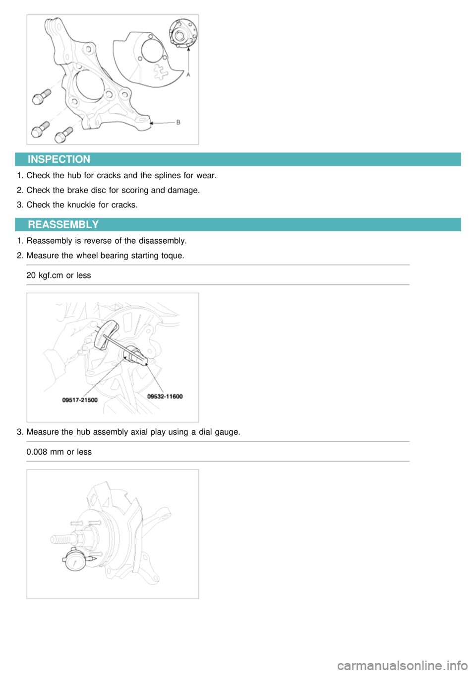
1.Check the hub for cracks and the splines for wear.
2. Check the brake disc for scoring and damage.
3. Check the knuckle for cracks.
REASSEMBLY
1.Reassembly is reverse of the disassembly.
2. Measure the wheel bearing starting toque.
20 kgf.cm or less
3.Measure the hub assembly axial play using a dial gauge.
0.008 mm or less
Page 481 of 1575

16.After loosening the castle nut and split pin, disconnect the upper arm (A) from the carrier assembly using a SST
(09562- 4A000).
Tightening torque Nm (kgf.m, lb - ft):
90 ~ 100 (9.0 ~ 10.0, 65 ~ 72)
17.Remove the carrier assembly (A) from the trailing arm by loosening the bolts.
Tightening torque Nm (kgf.m, lb - ft):
80 ~ 110 (8.0 ~ 11.0, 58 ~ 80)
INSTALLATION
1.Installation is the reverse of removal.
a.The rear hub lock nut should be replaced with new ones.
b. After installation lock nut, stake the lock nut using a chisel and hammer as shown in the illustration below.