reverse KIA CARNIVAL 2007 Manual PDF
[x] Cancel search | Manufacturer: KIA, Model Year: 2007, Model line: CARNIVAL, Model: KIA CARNIVAL 2007Pages: 1575, PDF Size: 44.86 MB
Page 779 of 1575

2007 > 2.7L V6 GASOLINE >
INSPECTION
1.Ignition "OFF"
2. Disconnect the intake actuator connector.
3. Verify that the actuator operates to the recirculation position when connecting 12V to the terminal 3 and grounding
terminal 4.
4. Verify that the intake actuator operates to the fresh position when connecting in the reverse.
5.If the intake actuator is not operated well, substitute with a known- good intake actuator and check for proper
operation.
6. If the problem is corrected, replace the intake actuator.
REPLACEMENT
1.Disconnect the negative ( - ) battery terminal.
2. Remove the glove box (Refer to BD group).
3. Disconnect the intake actuator connector.
4. Loosen the mounting screw and then remove the intake actuator (A) from the blower unit.
5.Installation is the reverse order of removal.
Page 784 of 1575
2007 > 2.7L V6 GASOLINE >
REPLACEMENT
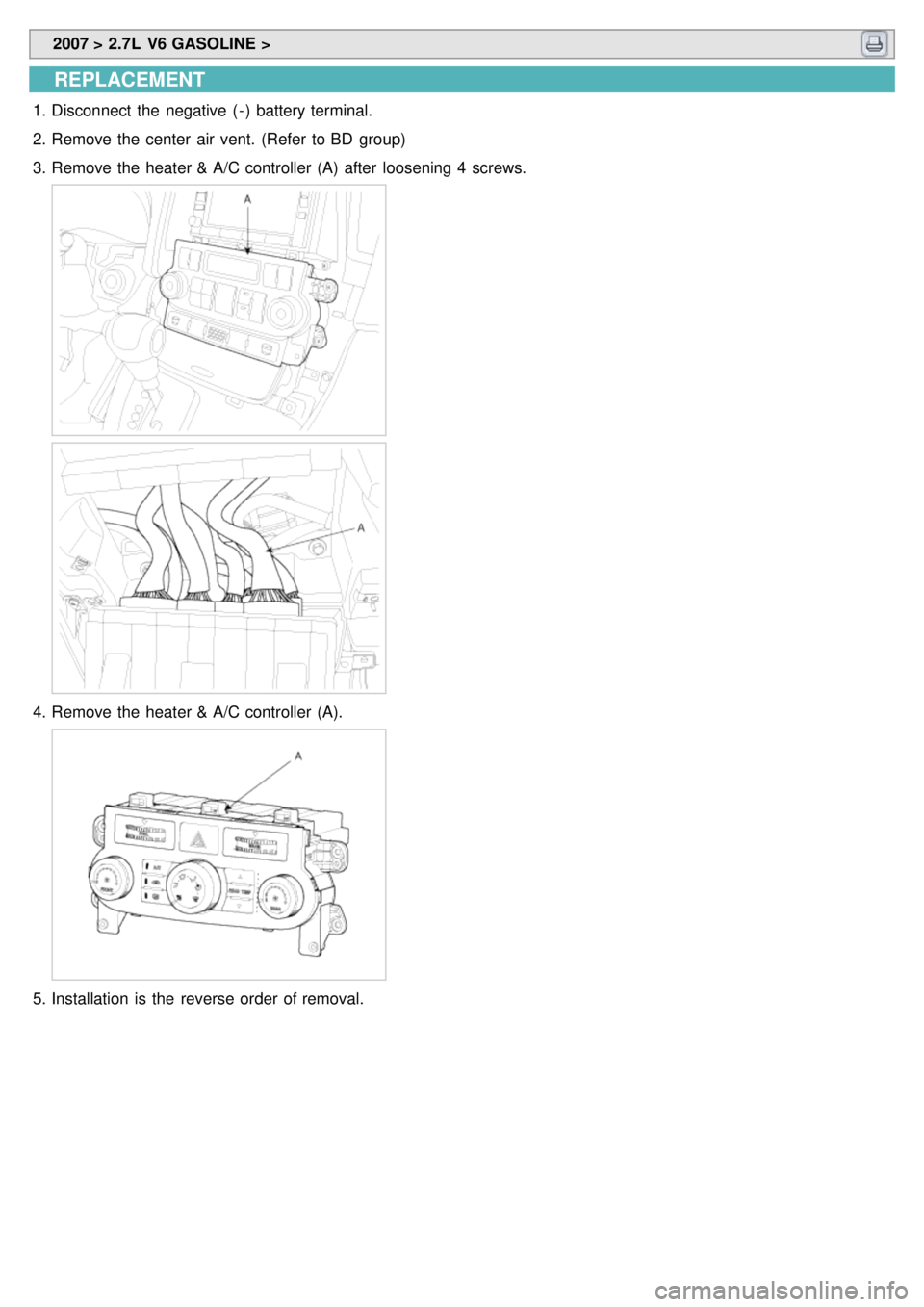
1.Disconnect the negative ( - ) battery terminal.
2. Remove the center air vent. (Refer to BD group)
3. Remove the heater & A/C controller (A) after loosening 4 screws.
4.Remove the heater & A/C controller (A).
5.Installation is the reverse order of removal.
Page 788 of 1575
2007 > 2.7L V6 GASOLINE >
REPLACEMENT
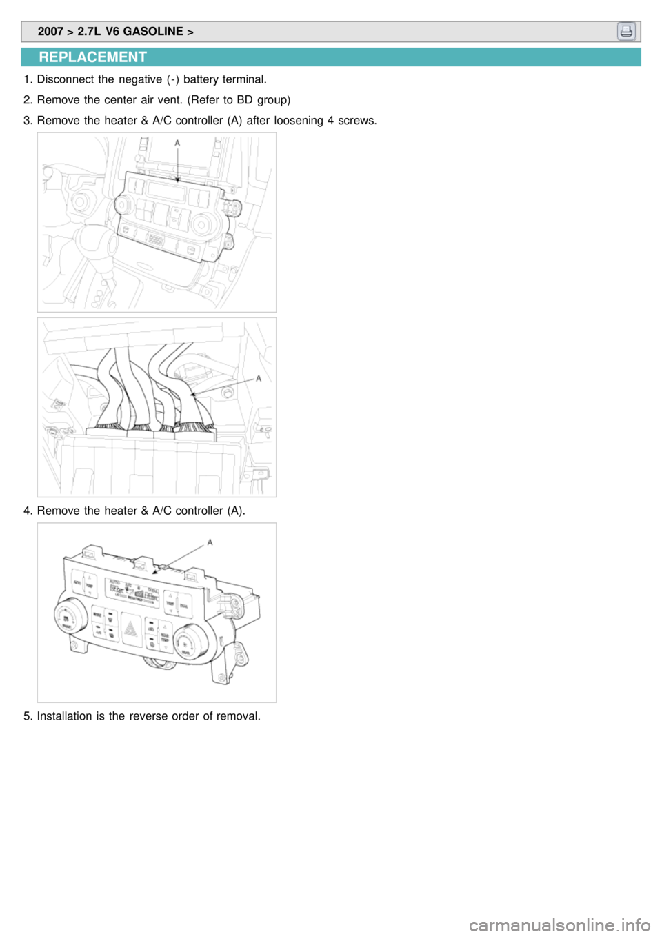
1.Disconnect the negative ( - ) battery terminal.
2. Remove the center air vent. (Refer to BD group)
3. Remove the heater & A/C controller (A) after loosening 4 screws.
4.Remove the heater & A/C controller (A).
5.Installation is the reverse order of removal.
Page 893 of 1575

2007 > 2.7L V6 GASOLINE >
REMOVAL
1.Remove the lower crash pad. (Refer to BD group 'Crash pad')
2. Remove the brake switch connector.
3. Remove the trans cable (A) in case of the adjustable brake pedal.
4.Remove the mounting bolt(A) of the peal position sensor connector in case of the adjustable brake pedal.
5.Remove the snap pin connecting the booster.
6. Remove the hinge shaft connecting the pedal tray.
7. Remove the brake pedal.
INSTALLATION
1.Installation is the reverse of removal.
Coat the inner surface of the bushings with the specified grease.
Specified grease : Lig- 2
2. Before inserting the pin, apply the specified grease to the clevis pin.
Page 950 of 1575
2007 > 2.7L V6 GASOLINE >
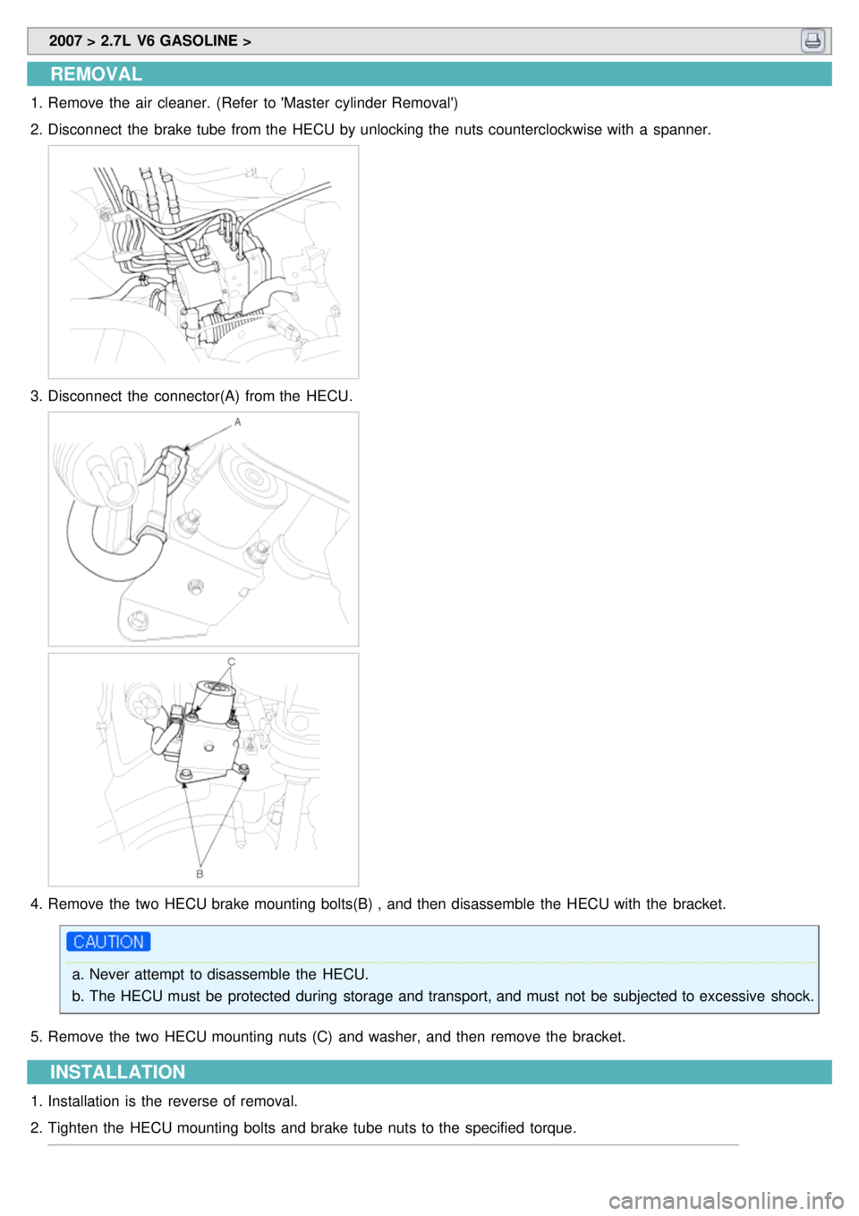
REMOVAL
1.Remove the air cleaner. (Refer to 'Master cylinder Removal')
2. Disconnect the brake tube from the HECU by unlocking the nuts counterclockwise with a spanner.
3.Disconnect the connector(A) from the HECU.
4.Remove the two HECU brake mounting bolts(B) , and then disassemble the HECU with the bracket.
a.Never attempt to disassemble the HECU.
b. The HECU must be protected during storage and transport, and must not be subjected to excessive shock.
5. Remove the two HECU mounting nuts (C) and washer, and then remove the bracket.
INSTALLATION
1.Installation is the reverse of removal.
2. Tighten the HECU mounting bolts and brake tube nuts to the specified torque.
Page 986 of 1575
2007 > 2.7L V6 GASOLINE >
DESCRIPTION
GENERAL DATA
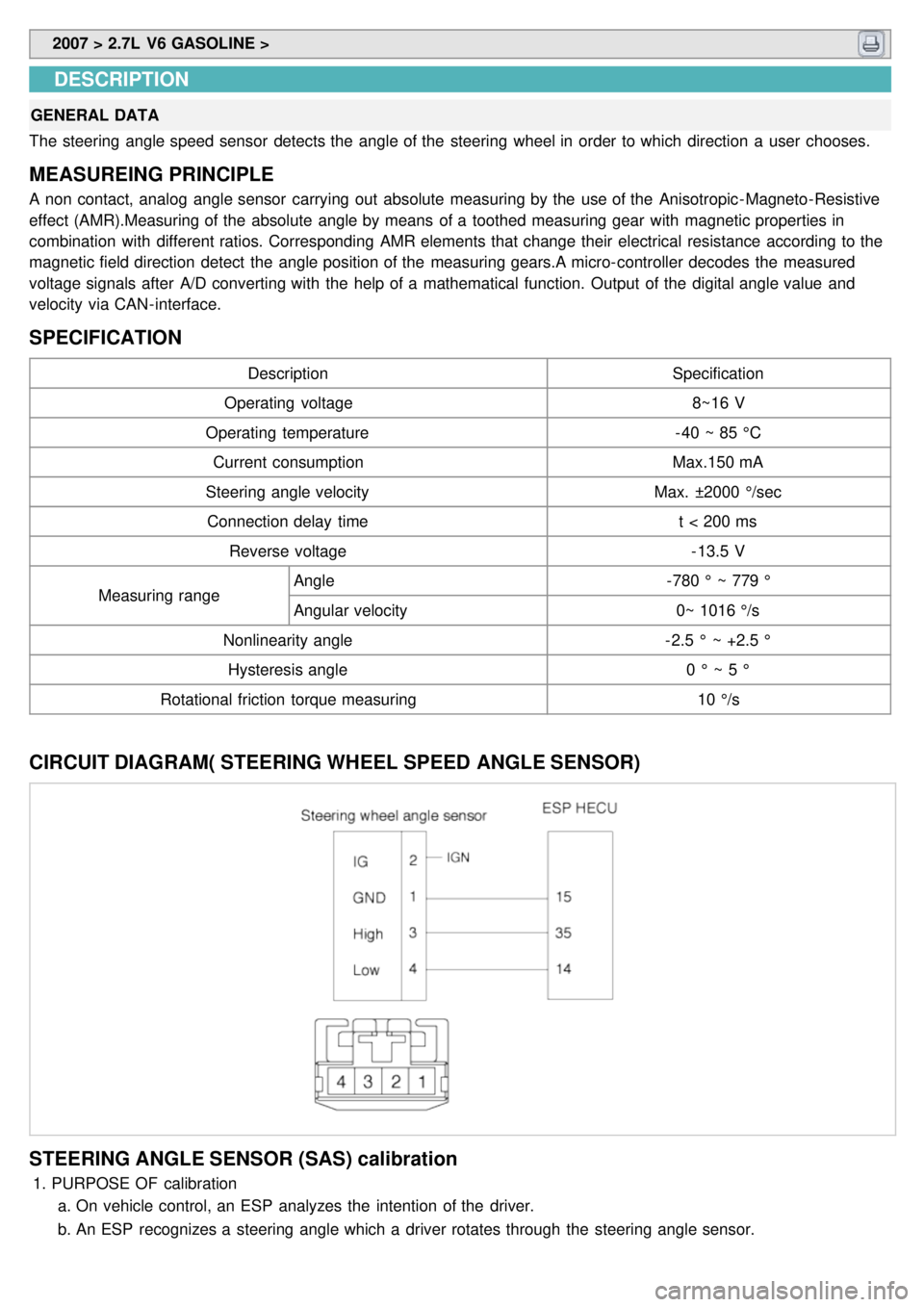
The steering angle speed sensor detects the angle of the steering wheel in order to which direction a user chooses.
MEASUREING PRINCIPLE
A non contact, analog angle sensor carrying out absolute measuring by the use of the Anisotropic - Magneto- Resistive
effect (AMR).Measuring of the absolute angle by means of a toothed measuring gear with magnetic properties in
combination with different ratios. Corresponding AMR elements that change their electrical resistance according to the
magnetic field direction detect the angle position of the measuring gears.A micro- controller decodes the measured
voltage signals after A/D converting with the help of a mathematical function. Output of the digital angle value and
velocity via CAN- interface.
SPECIFICATION
Description Specification
Operating voltage 8~16 V
Operating temperature - 40 ~ 85 °C
Current consumption Max.150 mA
Steering angle velocity Max. ±2000 °/sec
Connection delay time t < 200 ms
Reverse voltage - 13.5 V
Measuring range Angle
- 780 ° ~ 779 °
Angular velocity 0~ 1016 °/s
Nonlinearity angle - 2.5 ° ~ +2.5 °
Hysteresis angle 0 ° ~ 5 °
Rotational friction torque measuring 10 °/s
CIRCUIT DIAGRAM( STEERING WHEEL SPEED ANGLE SENSOR)
STEERING ANGLE SENSOR (SAS) calibration
1.PURPOSE OF calibration
a. On vehicle control, an ESP analyzes the intention of the driver.
b. An ESP recognizes a steering angle which a driver rotates through the steering angle sensor.
Page 997 of 1575

2007 > 2.7L V6 GASOLINE >
REPLACEMENT
a.Take care not to damage the hood and body.
b. When removing the clips, use a clip remover.
1. Remove the following items.
a. Headlamp assembly.
b. Front bumper.
c. Side garnish (B), mud guide (C), cover (D)
2. After loosening the fender mounting bolts, remove the fender (A).
3. Installation is the reverse of removal.
Page 999 of 1575

2007 > 2.7L V6 GASOLINE >
REPLACEMENT
HOOD ASSEMBLY REPLACEMENT
a. When removing and installing the hood, an assistant is necessary.
b. Take care not to damage the hood and body.
c. When removing the clips, use a clip remover.
1. Disconnect the windshield washer nozzle connecting tube (D).
2. Using a screwdriver (E), lift up slightly the socket clips (F) of both ends on the lifter (G), and then remove the lifter
from the bracket (H).
3. After loosen the hood hinge (B) mounting bolts, remove the hood (C).
4. Installation is the reverse of removal.
a.Make sure the hood opens properly and locks securely.
b. Adjust the hood alignment.
Page 1001 of 1575

2.Installation is the reverse of removal.
a.Replace any damaged clips.
HOOD WEATHERSTRIP REPLACEMENT
1.Detach the clips, then remove the hood weatherstrip(A). Take care not to scratch the hood.
2.Installation is the reverse of removal.
a.Replace any damaged clips.
HOOD SEAL WEATHERSTRIP REPLACEMENT
1.Detach the clips, then remove the hood weather strip(A). Take care not to scratch the hood.
Page 1002 of 1575

2.Installation is the reverse of removal.
a.Replace any damaged clips.
HOOD LIFT REPLACEMENT
1.Using a screwdriver (A), lift up slightly the socket clips (B) of both ends on the lifter (D), and then remove the lifter
from the bracket (C).
2.Push the socket of the lifter into the bracket for installation.
HOOD RELEASE HANDLE REPLACEMENT
1.Remove the mounting bolt, then remove the hood release handle (A).