reverse KIA CARNIVAL 2007 Service Manual
[x] Cancel search | Manufacturer: KIA, Model Year: 2007, Model line: CARNIVAL, Model: KIA CARNIVAL 2007Pages: 1575, PDF Size: 44.86 MB
Page 487 of 1575
2007 > 2.7L V6 GASOLINE >
TROUBLESHOOTING
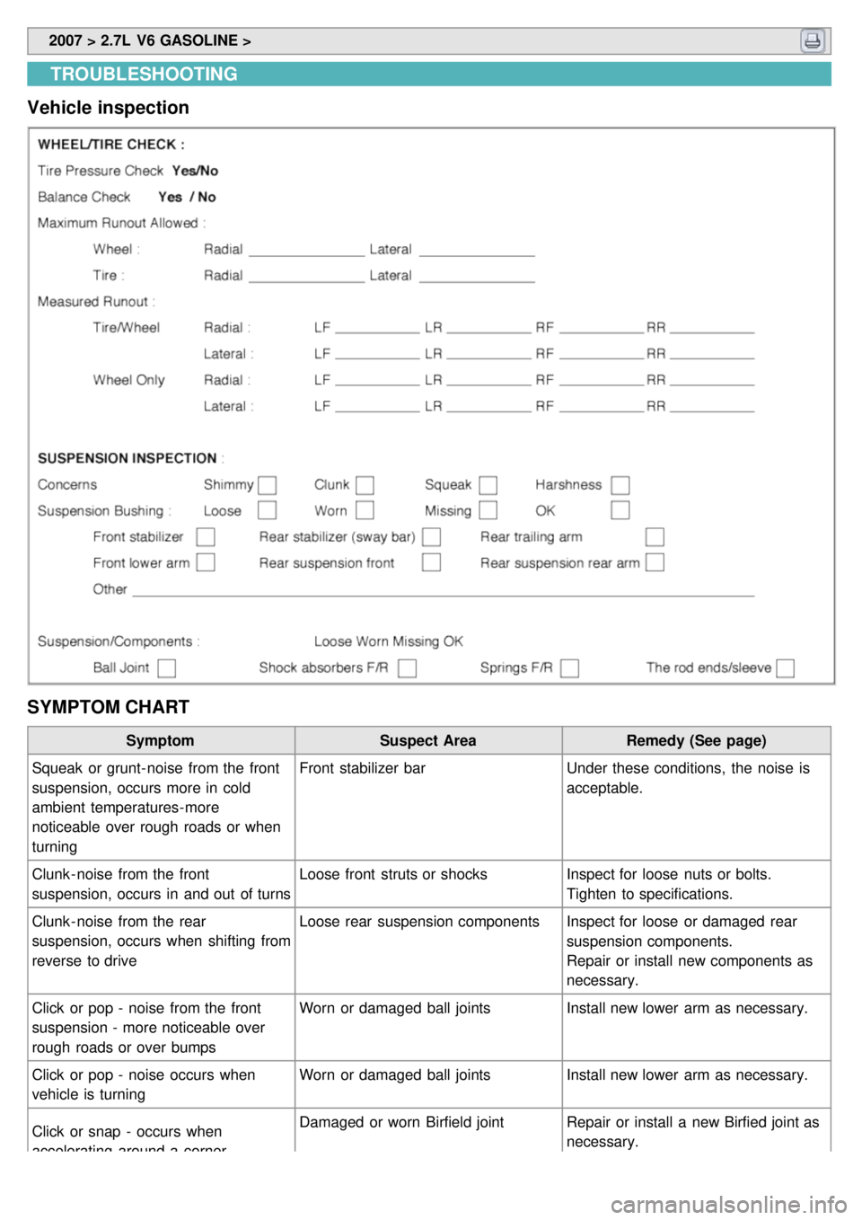
Vehicle inspection
SYMPTOM CHART
Symptom Suspect AreaRemedy (See page)
Squeak or grunt- noise from the front
suspension, occurs more in cold
ambient temperatures- more
noticeable over rough roads or when
turning Front stabilizer bar
Under these conditions, the noise is
acceptable.
Clunk - noise from the front
suspension, occurs in and out of turns Loose front struts or shocks
Inspect for loose nuts or bolts.
Tighten to specifications.
Clunk - noise from the rear
suspension, occurs when shifting from
reverse to drive Loose rear suspension components
Inspect for loose or damaged rear
suspension components.
Repair or install new components as
necessary.
Click or pop - noise from the front
suspension - more noticeable over
rough roads or over bumps Worn or damaged ball joints
Install new lower arm as necessary.
Click or pop - noise occurs when
vehicle is turning Worn or damaged ball joints
Install new lower arm as necessary.
Click or snap - occurs when
accelerating around a corner Damaged or worn Birfield joint
Repair or install a new Birfied joint as
necessary.
See DS group - driveshaft.
Page 593 of 1575

INSTALLATION
Before installing, apply multi purpose grease to each moving parts.
1. Installation is the reverse of removal.
Align the marks on the steering wheel and shaft for reinstallation when installing the steering wheel.
DISASSEMBLY
KEY LOCK ASSEMBLY
1. Make a groove on head of the special bolt (A) by using a punch.
2.Remove the key lock assembly (A) from the steering column (B) by loosing special bolts.
3.When reassembling the key lock assembly, loosely install new special bolts to the steering column shaft.
Page 594 of 1575

4.Tighten the special bolt until its head is cut off.
UNIVERSAL JOINT ASSEMBLY
1.Remove the universal joint (B) assembly from the steering column assembly (C) by loosening the bolt (A).
2.Reassembly is the reverse of disassembly.
INSPECTION
1.Check the steering column shaft for damage and deformation.
2. Check connection for play, damage and smooth operation.
3. Check the joint bearing for wear and damage.
Page 603 of 1575
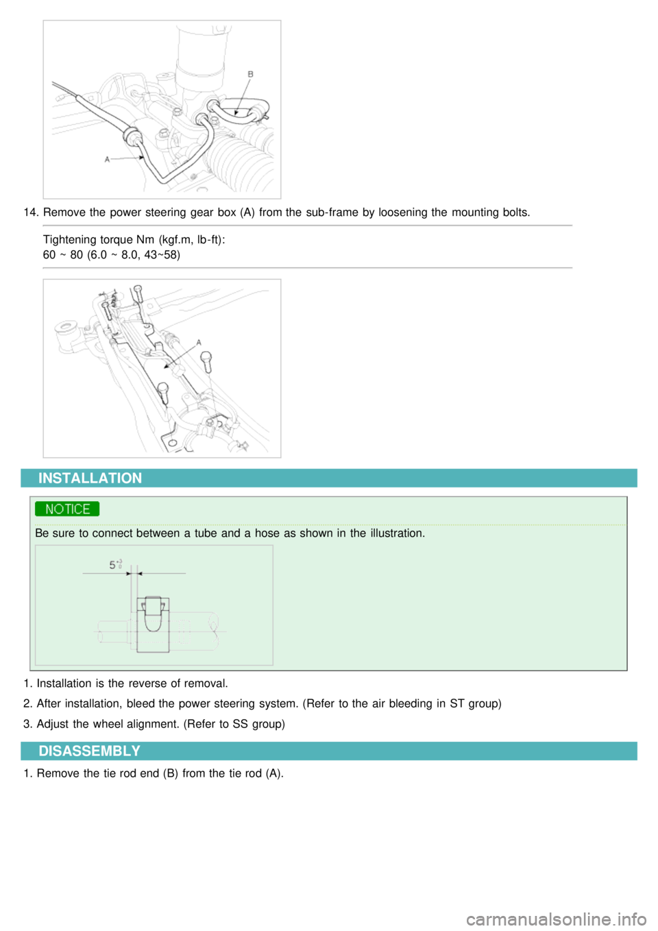
14.Remove the power steering gear box (A) from the sub- frame by loosening the mounting bolts.
Tightening torque Nm (kgf.m, lb - ft):
60 ~ 80 (6.0 ~ 8.0, 43~58)
INSTALLATION
Be sure to connect between a tube and a hose as shown in the illustration.
1.Installation is the reverse of removal.
2. After installation, bleed the power steering system. (Refer to the air bleeding in ST group)
3. Adjust the wheel alignment. (Refer to SS group)
DISASSEMBLY
1.Remove the tie rod end (B) from the tie rod (A).
Page 620 of 1575
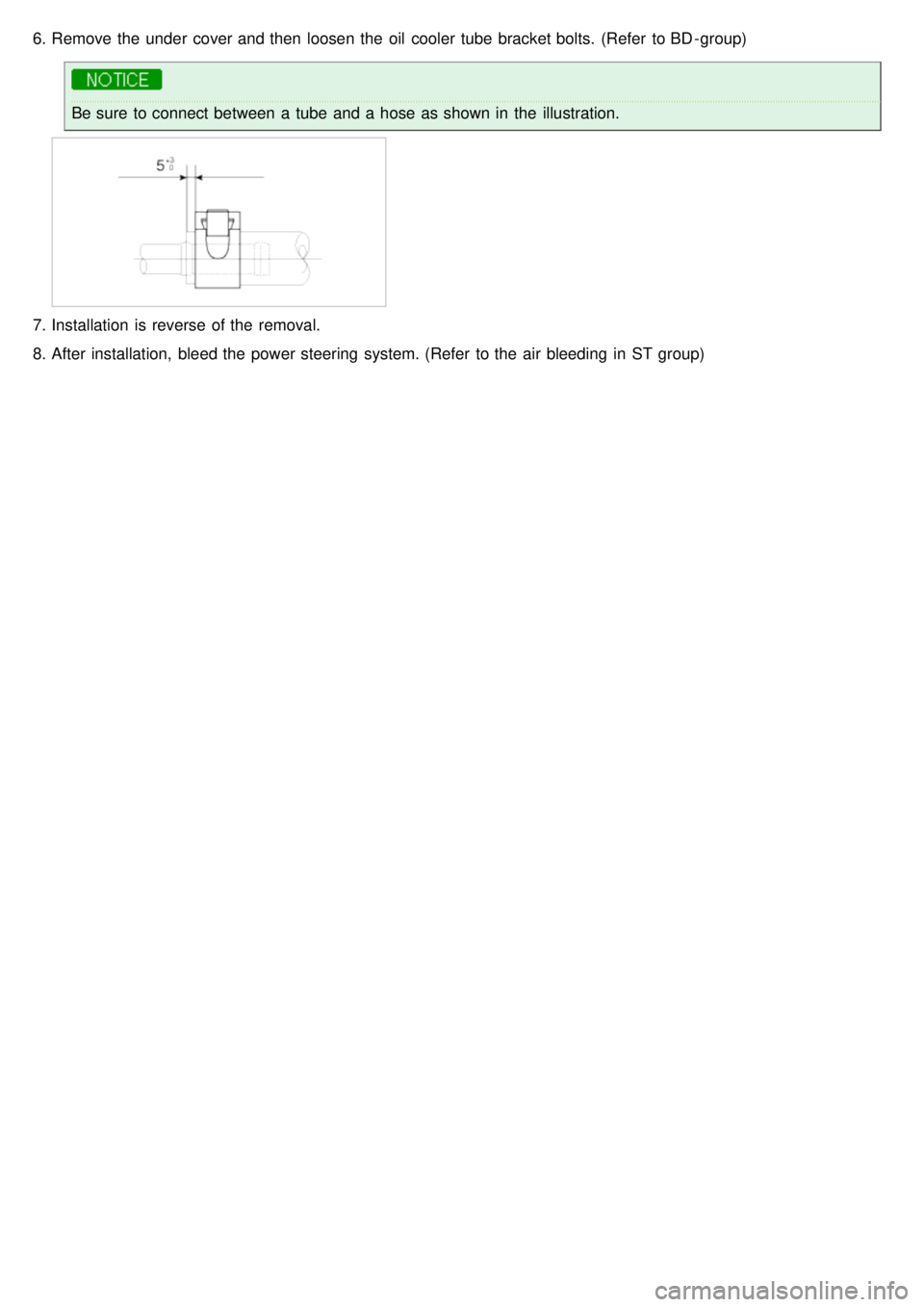
6.Remove the under cover and then loosen the oil cooler tube bracket bolts. (Refer to BD - group)
Be sure to connect between a tube and a hose as shown in the illustration.
7.Installation is reverse of the removal.
8. After installation, bleed the power steering system. (Refer to the air bleeding in ST group)
Page 624 of 1575

Tightening torque Nm (kgf.m lb - ft):
38 ~ 47 (3.8 ~ 4.7, 27 ~ 34)
[Diesel]
Tightening torque Nm (kgf.m lb - ft):
35 ~ 50 (3.5 ~ 5.0, 25 ~ 36)
[Gasoline]
Be careful not to spill fluid from the power steering oil pump.
INSTALLATION
1.Installation is the reverse of removal.
Page 660 of 1575
2007 > 2.7L V6 GASOLINE >
REMOVAL
1.If the compressor is marginally operable, run the engine at idle speed, and let the air conditioning work for a few
minutes, then shut the engine off.
2. Disconnect the negative cable from the battery.
3. Recover the refrigerant with a recovery/charging station (Refer to HA - 8).
4. Loosen the drive belt (Refer to HA - 14).
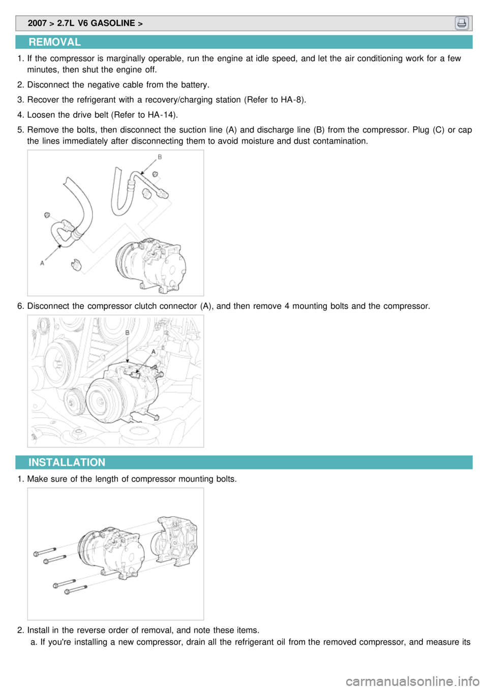
5. Remove the bolts, then disconnect the suction line (A) and discharge line (B) from the compressor. Plug (C) or cap
the lines immediately after disconnecting them to avoid moisture and dust contamination.
6.Disconnect the compressor clutch connector (A), and then remove 4 mounting bolts and the compressor.
INSTALLATION
1.Make sure of the length of compressor mounting bolts.
2.Install in the reverse order of removal, and note these items.
a. If you're installing a new compressor, drain all the refrigerant oil from the removed compressor, and measure its
volume, Subtract the volume of drained oil from 120cc(4.20 oz.) the result is the amount of oil you should drain
Page 663 of 1575

4.Remove the screw (A) from the field coil ground terminal. Remove the retainer ring (B) and then remove the field
coil (C) from the shaft with a puller. Be careful not to damage the coil and compressor.
5.Reassemble the compressor clutch in the reverse order of disassembly, and note these items :
a. Clean the pulley and compressor sliding surfaces with non- petroleum solvent.
b. Install new retainer rings, and make sure they are fully seated in the groove.
c. Make sure that the pulley turns smoothly after its reassembled.
Page 668 of 1575

2007 > 2.7L V6 GASOLINE >
INSPECTION
1.Check the condenser fins for clogging and damage. If clogged, clean them with water, and blow them with
compressed air. If bent, gently bend them using a screwdriver or pliers.
2. Check the condenser connections for leakage, and repair or replace it, if required.
REPLACEMENT
CONDENSER ASSEMBLY
1. Recover the refrigerant with a recovery/ recycling/ charging station (Refer to HA - 8).
2. Disconnect the negative ( - ) battery terminal.
3. Remove the radiator. (Refer to EM group)
4. Remove 2 bolts, and then remove the condenser (A) by lifting it up. Be careful not to damage the radiator and
condenser fins when removing the condenser.
5.Install in the reverse order of removal, and note these items :
a. If you're installing a new condenser, add refrigerant oil ND- OIL8.
b. Replace the O - rings with new ones at each fitting, and apply a thin coat of refrigerant oil before installing them.
Be sure to use the right O - rings for R- 134a to avoid leakage.
c. Be careful not to damage the radiator and condenser fins when installing the condenser.
d. Be sure to install the lower mount cushions of condenser securely into the holes.
e. Charge the system, and test its performance. (Refer to HA - 9)
DESICCANT
1.Remove the condenser, and then remove the bottom cap (B) with L wrench (A) from the condenser.
TORQUE: 20~25N.m (2.0~2.5kgf•m, 14.5~18.2lb - ft)
Page 681 of 1575

3.Disconnect the evaporator sensor connector (A).
4. Loosen 2 screws and then remove the evaporator sensor cover(B).
5. Remove the evaporator sensor.
Take care that evaporator core pins are not bent.
6. Installation is the reverse order of removal.