display KIA CARNIVAL 2007 Workshop Manual
[x] Cancel search | Manufacturer: KIA, Model Year: 2007, Model line: CARNIVAL, Model: KIA CARNIVAL 2007Pages: 1575, PDF Size: 44.86 MB
Page 141 of 1575

2007 > 2.7L V6 GASOLINE >
THE MICRO 570 ANALYZER
The MICRO 570 Analyzer provides the ability to test the charging and starting systems, including the battery, starter
and generator.
Because of the possibility of personal injury, always use extreme caution and appropriate eye protection when
working with batteries.
KEYPAD
The MICRO570 button on the key pad provides the following functions :
BATTERY TEST PROCEDURE
1.Connect the tester to the battery.
a. Red clamp to battery positive (+) terminal.
b. Black clamp to battery negative ( - ) terminal.
Connect clamps securely. If "CHECK CONNECTION" message is displayed on the screen, reconnect clamps
securely.
Page 142 of 1575

2.The tester will ask if the battery is connected "IN A VEHICLE" or "OUT OF A VEHICLE". Make your selection by
pressing the arrow buttons; then press ENTER.
3.Choose either CCA or CCP and press the ENTER button.
a.CCA : Cold cranking amps, is an SAE specification for cranking batteries at - 18°C (0°F).
b. CCP : Cold cranking amps, is an SAE specification for korean manufacturer's for cranking batteries at -
18°C (0°F).
4. Set the CCA value displayed on the screen to the CCA value marked on the battery label by pressing up and
down buttons and press ENTER.
The battery ratings(CCA) displayed on the tester must be identical to the ratings marked on battery label.
5. The tester (Micro570) displays battery test results including voltage and battery ratings.
A relevant action must be given according to the test results by referring to the battery test results as shown in the
table below.
Page 143 of 1575

The battery ratings (CCA) displayed on the tester must be identical to the ratings marked on battery label.
6. To conduct starter test, press ENTER.
BATTERY TEST RESULTS
RESULT ON PRINTER REMEDY
Good battery No action is required
Good recharge Battery is in a good state
Recharge the battery and use
Charge & Retest Battery is not charged properly
=> Charge and test the battery again (Failure to charge
the battery fully may read incorrect measurement value)
Replace battery => Replace battery and recheck the charging system.
(Improper connection between battery and vehicle cables
may cause "REPLACE BATTERY", retest the battery
after removing cables and connecting the tester to the
battery terminal directly prior to replacing the battery)
Bad cell- replace => Charge and retest the battery. And then, test results
may cause "REPLACE BATTERY", replace battery and
recheck the charging system
Whenever filing a claim for battery, the print out of the battery test results must be attached.
STARTER TEST PROCEDURE
1.
After the battery test, press ENTER immediately for the starter test.
Page 144 of 1575

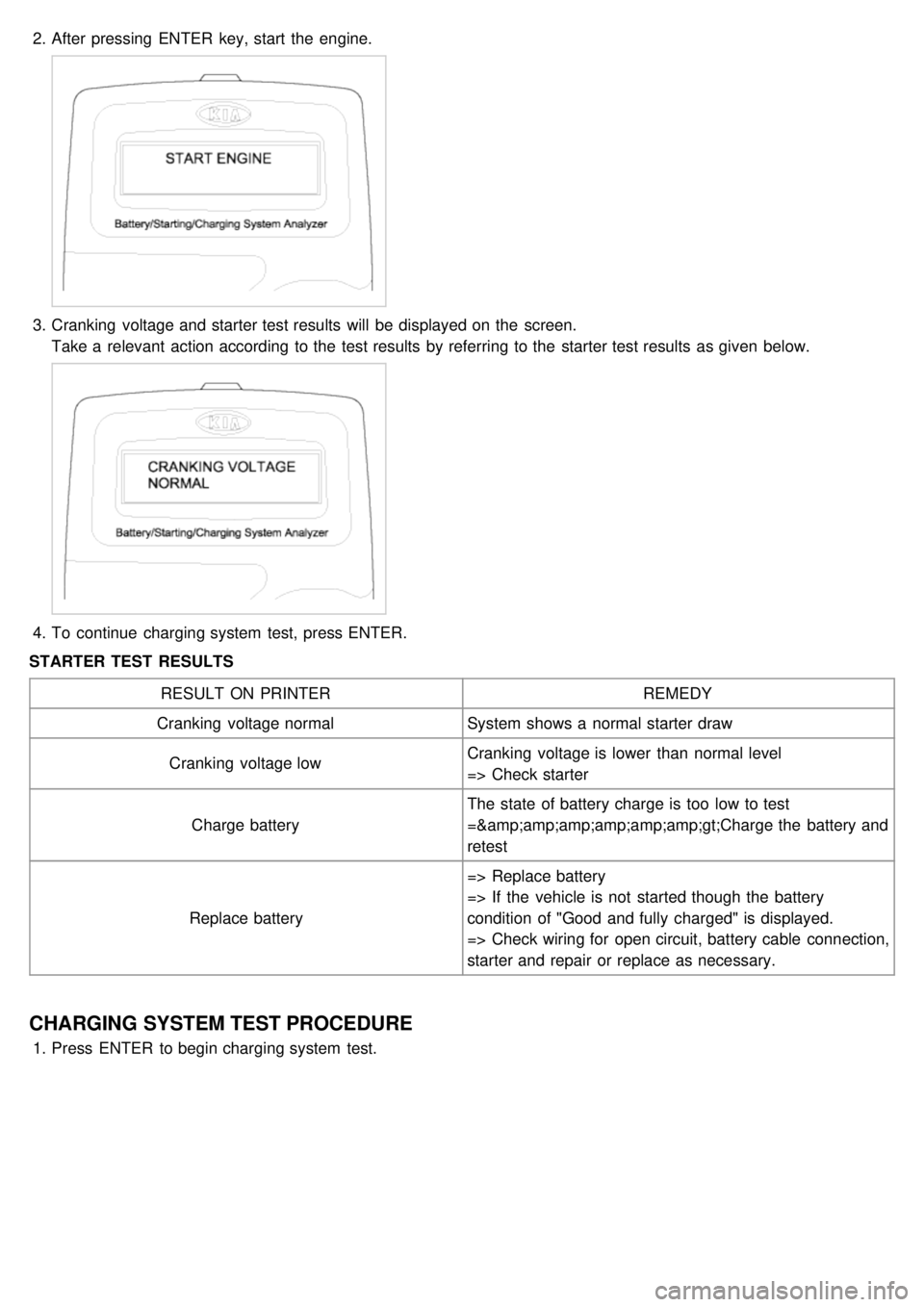
2.After pressing ENTER key, start the engine.
3.Cranking voltage and starter test results will be displayed on the screen.
Take a relevant action according to the test results by referring to the starter test results as given below.
4.To continue charging system test, press ENTER.
STARTER TEST RESULTS
RESULT ON PRINTER REMEDY
Cranking voltage normal System shows a normal starter draw
Cranking voltage low Cranking voltage is lower than normal level
=> Check starter
Charge battery The state of battery charge is too low to test
=>Charge the battery and
retest
Replace battery => Replace battery
=> If the vehicle is not started though the battery
condition of "Good and fully charged" is displayed.
=> Check wiring for open circuit, battery cable connection,
starter and repair or replace as necessary.
CHARGING SYSTEM TEST PROCEDURE
1.
Press ENTER to begin charging system test.
Page 145 of 1575

2.ENTER button is pressed, the tester displays the actual voltage of generator.
Press ENTER to test the charging system.
3.The MICRO 570 will prompt you to rev the engine until the rev detected. It will then collect the data.
4.Press ENTER.
5.The MICRO 570 will analyze the charging system output at idle for comparison to other readings.
Page 146 of 1575

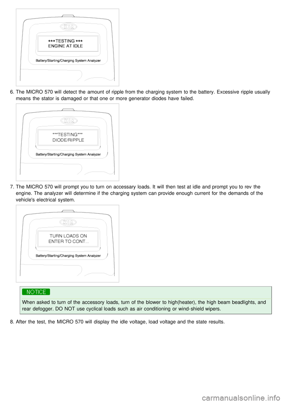
6.The MICRO 570 will detect the amount of ripple from the charging system to the battery. Excessive ripple usually
means the stator is damaged or that one or more generator diodes have failed.
7.The MICRO 570 will prompt you to turn on accessary loads. It will then test at idle and prompt you to rev the
engine. The analyzer will determine if the charging system can provide enough current for the demands of the
vehicle's electrical system.
When asked to turn of the accessory loads, turn of the blower to high(heater), the high beam beadlights, and
rear defogger. DO NOT use cyclical loads such as air conditioning or wind- shield wipers.
8. After the test, the MICRO 570 will display the idle voltage, load voltage and the state results.
Page 365 of 1575

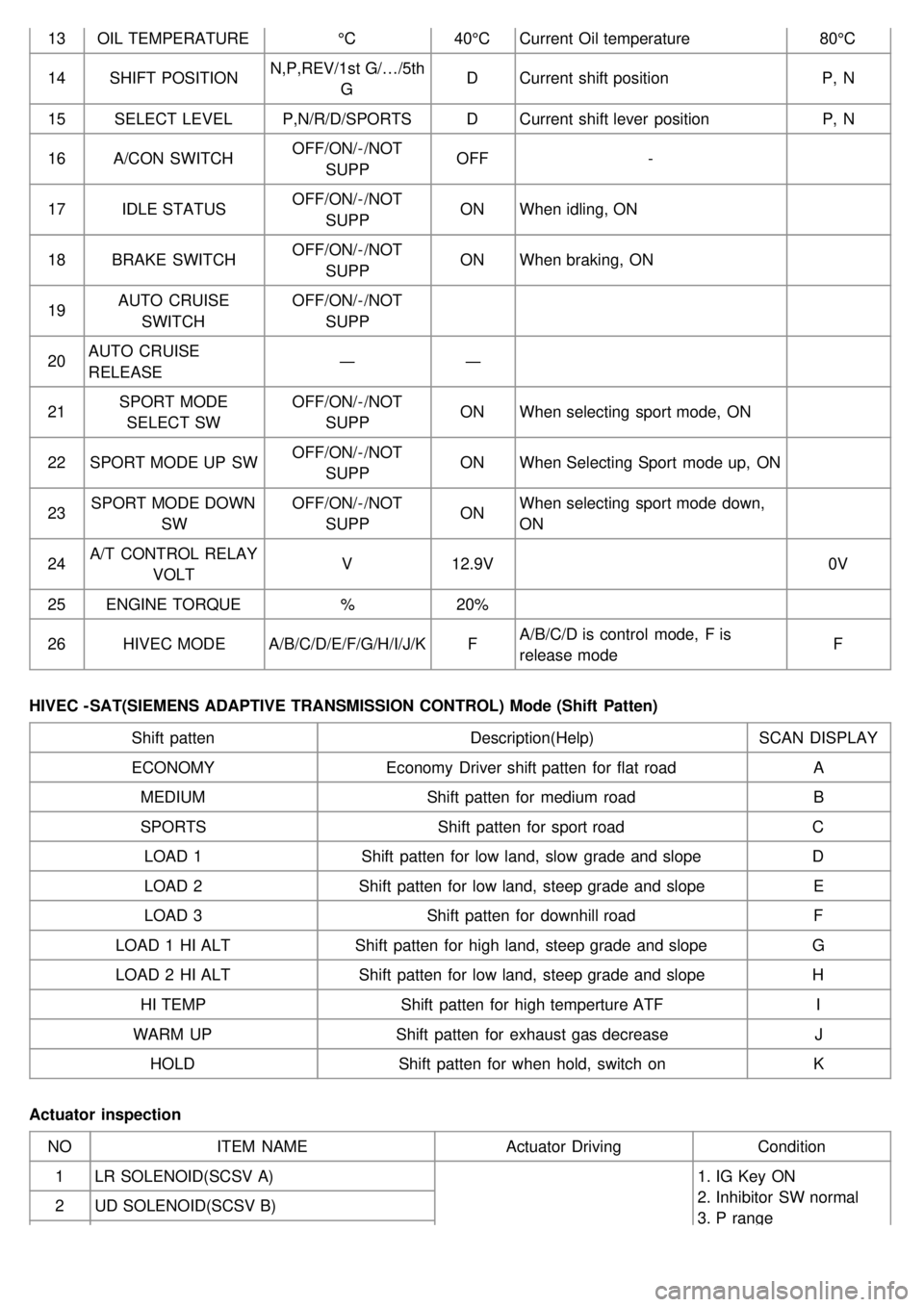
13OIL TEMPERATURE °C40°CCurrent Oil temperature 80°C
14 SHIFT POSITION N,P,REV/1st G/…/5th
G D
Current shift position P, N
15 SELECT LEVEL P,N/R/D/SPORTS DCurrent shift lever position P, N
16 A/CON SWITCH OFF/ON/- /NOT
SUPP OFF
-
17 IDLE STATUS OFF/ON/- /NOT
SUPP ON
When idling, ON
18 BRAKE SWITCH OFF/ON/- /NOT
SUPP ON
When braking, ON
19 AUTO CRUISE
SWITCH OFF/ON/- /NOT
SUPP
20 AUTO CRUISE
RELEASE ―
―
21 SPORT MODE
SELECT SW OFF/ON/- /NOT
SUPP ON
When selecting sport mode, ON
22 SPORT MODE UP SW OFF/ON/- /NOT
SUPP ON
When Selecting Sport mode up, ON
23 SPORT MODE DOWN
SW OFF/ON/- /NOT
SUPP ON
When selecting sport mode down,
ON
24 A/T CONTROL RELAY
VOLT V
12.9V 0V
25 ENGINE TORQUE %20%
26 HIVEC MODE A/B/C/D/E/F/G/H/I/J/K FA/B/C/D is control mode, F is
release mode F
HIVEC - SAT(SIEMENS ADAPTIVE TRANSMISSION CONTROL) Mode (Shift Patten) Shift patten Description(Help)SCAN DISPLAY
ECONOMY Economy Driver shift patten for flat road A
MEDIUM Shift patten for medium road B
SPORTS Shift patten for sport road C
LOAD 1 Shift patten for low land, slow grade and slope D
LOAD 2 Shift patten for low land, steep grade and slope E
LOAD 3 Shift patten for downhill road F
LOAD 1 HI ALT Shift patten for high land, steep grade and slope G
LOAD 2 HI ALT Shift patten for low land, steep grade and slope H
HI TEMP Shift patten for high temperture ATF I
WARM UP Shift patten for exhaust gas decrease J
HOLD Shift patten for when hold, switch on K
Actuator inspection NO ITEM NAME Actuator DrivingCondition
1 LR SOLENOID(SCSV A) 1. IG Key ON
2. Inhibitor SW normal
3. P range
2
UD SOLENOID(SCSV B)
Page 737 of 1575

2007 > 2.7L V6 GASOLINE >
INSPECTION
Inspect the PTC operation by confirmation logic as below.
1. Entering method
(1) Set the floor mode, maximum heating
(2) Turn off the blower switch
(3) Press the intake button more than 5 times.
(4) Indicator of entire button is flashed with an interval of 0.5 seconds continuously (Manual).
Graphics of the entire LCD display switch on and off with an interval of 0.5 seconds continuously (Automatic)
(5) Confirm the PTC operation by operating the blower switch
Manual : 1~4 step, Automatic: 1~8step.
(6) Each PTC relay is operated with an interval of 3 seconds.
(7) Execute the PTC operation by confirmation logic for 30 seconds.
2. Cancellation method
(1) Select the A/C button or intake button.
(2) IG "OFF".
(3) Cancel the logic after 30 seconds automatically.
3. If the PTC operation is not operated, substitute with a known- good PTC and check for proper operation.
If the problem is corrected, replace the PTC.
Page 937 of 1575

c.Stop lamp switch circuit.
d. Check the hydraulic circuit for leakage.
Communication with Scan tool is not possible.
(Communication with any system is not possible) a.
Power source circuit
b. Diagnosis line
Communication with Scan tool is not possible.
(Communication with ABS only is not possible) a.
Power source circuit
b. Diagnosis line
c. HECU
When ignition key is turned ON (engine OFF), the ABS
warning lamp does not light up. a.
ABS warning lamp circuit
b. HECU
Even after the engine is started, the ABS warning lamp
remains ON. a.
ABS warning lamp circuit
b. HECU
During ABS operation, the brake pedal may vibrate or may not be able to be depressed. Such phenomena are
due to intermittent changes in hydraulic pressure inside the brake line to prevent the wheels from locking and is
not an abnormality.
DETECTING CONDITION
Trouble Symptoms Possible Cause
Brake operation varies depending on driving conditions and road
surface conditions, so diagnosis can be difficult.However if a normal
DTC is displayed, check the following probable cause. When the
problem is still occurring, replace the ABS control module. a.
Inoperative power source circuit
b. Inoperative wheel speed sensor circuit
c. Inoperative hydraulic circuit for leakage
d. Inoperative HECU
INSPECTION PROCEDURES
DTC INSPECTION
1. Connect the Scan Tool with the data link connector and turn the ignition switch ON.
2. Verify that the system is operating to specifications.
Is the system operating to specifications ?
▶ Check the power source circuit.
▶ Erase the DTC and recheck using Scan Tool.
CHECK THE POWER SOURCE CIRCUIT.
1. Disconnect the connector from the ABS control module.
2. Turn the ignition switch ON, measure the voltage between terminal 18 of the ABS control module harness side
connector and body ground.
Specification: approximately B+
Is the voltage within specification?
▶ Check the ground circuit.
▶ Check the harness or connector between the fuse (10A) in the engine compartment junction block and the ABS
control module. Repair if necessary.
Page 938 of 1575

control module. Repair if necessary.
CHECK THE GROUND CIRCUIT.
1.Disconnect the connector from the ABS control module.
2. Check for continuity between terminals 1,4 of the ABS control module harness side connector and ground point.
Is there continuity?
▶ Check the wheel speed sensor circuit.
▶ Repair an open in the wire and ground point.
CHECK THE WHEEL SPEED SENSOR CIRCUIT.
Refer to the DTC troubleshooting procedures.
Is the system operating to specifications ?
▶ Check the hydraulic circuit for leakage.
▶ Repair or replace the wheel speed sensor.
CHECK THE HYDRAULIC CIRCUIT FOR LEAKAGE.
Refer to the hydraulic lines.
Inspect leakage of the hydraulic lines.
Is the system operating to specifications ?
▶ The problem is still occurring, replace the ABS control module.
▶ Replace the leaking hydraulic lines.
DETECTING CONDITION
Trouble Symptoms Possible Cause
Brake operation varies depending on driving conditions and road
surface conditions, so diagnosis can be difficult.However if a normal
DTC is displayed, check the following probable cause. When the a.
Inoperative power source circuit
b. Inoperative wheel speed sensor circuit