Lancia Flavia 2012 Owner handbook (in English)
Manufacturer: LANCIA, Model Year: 2012, Model line: Flavia, Model: Lancia Flavia 2012Pages: 233, PDF Size: 2.61 MB
Page 131 of 233

AUTOMATIC
TEMPERATURE CONTROL
(ATC)
Automatic Operation
The Automatic Temperature Control
system automatically maintains the
climate in the cabin of the vehicle at
the comfort levels desired by the
driver and passenger.
Operation of the system is quite
simple.
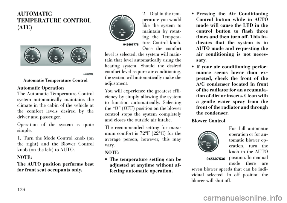
1. Turn the Mode Control knob (on
the right) and the Blower Control
knob (on the left) to AUTO.
NOTE:
The AUTO position performs best
for front seat occupants only.2.
Dial in the tem-
perature you would
like the system to
maintain by rotat-
ing the Tempera-
ture Control knob.
Once the comfort
level is selected, the system will main-
tain that level automatically using the
heating system. Should the desired
comfort level require air conditioning,
the system will automatically make the
adjustment.
You will experience the greatest effi-
ciency by simply allowing the system
to function automatically. Selecting
the “O” (OFF) position on the blower
control stops the system completely
and closes the outside air intake.
The recommended setting for maxi-
mum comfort is 72°F (22°C) for the
average person; however, this may
vary.
NOTE:
The temperature setting can be adjusted at anytime without af-
fecting automatic operation. Pressing the Air Conditioning
Control button while in AUTO
mode will cause the LED in the
control button to flash three
times and then turn off. This in-
dicates that the system is in
AUTO mode and requesting the
air conditioning is not neces-
sary.
If your air conditioning perfor- mance seems lower than ex-
pected, check the front of the
A/C condenser located in front
of the radiator for an accumula-
tion of dirt or insects. Clean with
a gentle water spray from the
front of the radiator and through
the condenser.
Blower Control
For full automatic
operation or for au-
tomatic blower op-
eration, turn the
knob to the AUTO
position. In manual
mode there are
seven blower speeds that can be indi-
vidual selected. In off position the
blower will shut off.
Automatic Temperature Control
124
Page 132 of 233

Manual Operation
This system offers a full complement
of manual override features, which
consist of Blower Preferred Auto-
matic, Mode Preferred Automatic, or
Blower and Mode Preferred Auto-
matic. This means the operator can
override the blower, the mode, orboth. There is a manual blower range
for times when the AUTO setting is
not desired. The blower can be set to
any fixed blower speed by rotating the
Blower Control knob (on the left).
NOTE:
Please read the Automatic Tem-
perature Control Operation Chart
that follows for details.
125
Page 133 of 233

The operator can override the AUTO
mode setting to change airflow distri-
bution by rotating the Mode Control
knob (on the right) to one of the fol-
lowing positions.
PanelAir is directed through the outlets
in the instrument panel. These
outlets can be adjusted to direct
airflow.
NOTE:
The center instrument panel out-
lets can be aimed so that they are
directed toward the rear seat pas-
sengers for maximum airflow to
the rear.
Bi-Level Air is directed through the panel
and floor outlets.
NOTE:
For all settings, except full cold or
full hot, there is a difference in
temperature between the upper
and lower outlets. The warmer air
flows to the floor outlets. This fea-
ture gives improved comfort dur-
ing sunny but cool conditions. Floor
Air is directed through the floor
outlets with a small amount
flowing through the defrost and
side window demist outlets.
Mix Air is directed through the floor,
defrost, and side window demist
outlets. This setting works best
in cold or snowy conditions that re-
quire extra heat to the windshield.
This setting is good for maintaining
comfort while reducing moisture on
the windshield.
Defrost Air is directed through the
windshield and side window
demist outlets. Use this mode
with maximum blower and tempera-
ture settings for best windshield and
side window defrosting. Air Conditioner Control
Press this button to
turn on the air con-
ditioning during
manual operation
only. When the air
conditioning is
turned on, cool de-
humidified air will flow through the
outlets selected with the Mode control
dial. Press this button a second time to
turn OFF the air conditioning. An
LED in the button illuminates when
manual compressor operation is se-
lected.
Recirculation Control The system will automati-
cally control recirculation.
However, pressing the Re-
circulation Control button
will put the system in recirculation
mode. This can be used when outside
conditions such as smoke, odors, dust,
or high humidity are present. Activat-
ing recirculation will cause the LED
in the control button to illuminate.126
Page 134 of 233

NOTE:
When the ignition switch isturned to the LOCK position, the
recirculation feature will be
cancelled.
In cold weather, use of the Recir- culation mode may lead to ex-
cessive window fogging. The Re-
circulation mode is not allowed
in the floor, defrost, or defrost/
floor mode in order to improve
window clearing. Recirculation
will be disabled automatically if
these modes are selected.
Extended use of recirculation may cause the windows to fog. If
the interior of the windows be-
gins to fog, press the Recircula-
tion button to return to outside
air. Some temp/humidity condi-
tions will cause captured inte-
rior air to condense on windows
and hamper visibility. For this
reason, the system will not allow
Recirculation to be selected
while in defrost mode. Attempt-
ing to use the recirculation while
in this mode will cause the LED in the control button to blink
and then turn off.
Most of the time, when in Auto- matic Operation, you can tem-
porarily put the system into Re-
circulation Mode by pressing the
Recirculation button. However,
under certain conditions, while
in Automatic Mode, the system is
blowing air out the defrost vents.
When these conditions are pres-
ent, and the Recirculation but-
ton is pressed, the indicator will
flash and then turn off. This tells
you that you are unable to go
into Recirculation Mode at this
time. If you would like the sys-
tem to go into Recirculation
Mode, you must first move the
Mode knob to Panel, Bi-Level,
or Mix, and then press the Recir-
culation button. This feature re-
duces the possibility of window
fogging. OPERATING TIPS
NOTE:
Refer to the chart at the end of this
section for suggested control set-
tings for various weather condi-
tions.
Summer Operation
The engine cooling system in air-
conditioned vehicles must be pro-
tected with a high-quality antifreeze
coolant to provide proper corrosion
protection and to protect against en-
gine overheating. A solution of 50%
ethylene glycol antifreeze coolant and
50% water is recommended. Refer to
“Maintenance Procedures” in “Main-
taining Your Vehicle” for proper cool-
ant selection.
Winter Operation
Use of the air Recirculation Mode dur-
ing winter months is not recom-
mended because it may cause window
fogging.
127
Page 135 of 233

Vacation Storage
Anytime you store your vehicle, or
keep it out of service (i.e., vacation)
for two weeks or more, run the air
conditioning system at idle for about
five minutes in the fresh air and high
blower settings. This will ensure ad-
equate system lubrication to minimize
the possibility of compressor damage
when the system is started again.
Window Fogging
Interior fogging on the windshield can
be quickly removed by turning the
mode selector to Defrost. The Defrost/
Floor mode can be used to maintain a
clear windshield and provide suffi-
cient heating. If side window fogging
becomes a problem, increase blower
speed. Vehicle windows tend to fog on
the inside in mild but rainy or humid
weather.NOTE:
Recirculate without A/C should
not be used for long periods as
fogging may occur.
Side Window Demisters
A side window demister outlet is lo-
cated at each end of the instrument
panel. These non-adjustable outlets
direct air toward the side windows
when the system is in the FLOOR,
MIX, or DEFROST mode. The air is
directed at the area of the windows
through which you view the outside
mirrors.
Outside Air Intake
Make sure the air intake, located di-
rectly in front of the windshield, is
free of obstructions such as leaves.
Leaves collected in the air intake may
reduce airflow, and if they enter the
plenum, they could plug the water
drains. In winter months, make sure
the air intake is clear of ice, slush, and
snow.A/C Air Filter
The A/C Filter prevents most dust
and pollen from entering the cabin.
The filter acts on air coming from
outside the vehicle and recirculated
air within the passenger compart-
ment. Refer to “Maintenance Proce-
dures” in “Maintaining Your Vehicle”
for A/C Air Filter service information
or see your authorized dealer for ser-
vice. Refer to “Maintenance Sched-
ules” for filter service intervals.
128
Page 136 of 233

Control Setting Suggestions for Various Weather Conditions
129
Page 137 of 233

130
Page 138 of 233

5
STARTING AND OPERATING
STARTING PROCEDURES . . . . . . . . . . . . . . . . . 134 AUTOMATIC TRANSMISSION . . . . . . . . . . . . 134
NORMAL STARTING . . . . . . . . . . . . . . . . . . . 134
IF ENGINE FAILS TO START . . . . . . . . . . . . . 134
AFTER STARTING . . . . . . . . . . . . . . . . . . . . . 135
AUTOMATIC TRANSMISSION . . . . . . . . . . . . . . 135 AUTOMATIC TRANSMISSION IGNITIONINTERLOCK SYSTEMS . . . . . . . . . . . . . . . . . 136
KEY IGNITION PARK INTERLOCK . . . . . . . . 136
BRAKE/TRANSMISSION INTERLOCK SYSTEM . . . . . . . . . . . . . . . . . . . . . . . . . . . . 136
SIX-SPEED AUTOMATIC TRANSMISSION . . 137
GEAR RANGES . . . . . . . . . . . . . . . . . . . . . . . 137
AUTOSTICK® . . . . . . . . . . . . . . . . . . . . . . . . . . 141 OPERATION . . . . . . . . . . . . . . . . . . . . . . . . . 141
GENERAL INFORMATION . . . . . . . . . . . . . . . 141
DRIVING ON SLIPPERY SURFACES . . . . . . . . . 142 ACCELERATION . . . . . . . . . . . . . . . . . . . . . . 142
TRACTION . . . . . . . . . . . . . . . . . . . . . . . . . . . 142
DRIVING THROUGH WATER . . . . . . . . . . . . . . 142 FLOWING/RISING WATER . . . . . . . . . . . . . . 142
131
Page 139 of 233

SHALLOW STANDING WATER . . . . . . . . . . . 143
POWER STEERING . . . . . . . . . . . . . . . . . . . . . . 144 POWER STEERING FLUID CHECK . . . . . . . . 144
PARKING BRAKE . . . . . . . . . . . . . . . . . . . . . . . 145
ANTI-LOCK BRAKE SYSTEM (ABS) . . . . . . . . . 146
ELECTRONIC BRAKE CONTROL SYSTEM . . . . 147 ANTI-LOCK BRAKE SYSTEM (ABS) . . . . . . . 147
TRACTION CONTROL SYSTEM (TCS) . . . . . . 148
BRAKE ASSIST SYSTEM (BAS) . . . . . . . . . . . 148
ELECTRONIC STABILITY CONTROL (ESC) . . 149
ESC ACTIVATION/MALFUNCTIONINDICATOR LIGHT AND ESC OFF
INDICATOR LIGHT . . . . . . . . . . . . . . . . . . . . 150
TIRES — GENERAL INFORMATION . . . . . . . . . 151 TIRE PRESSURE . . . . . . . . . . . . . . . . . . . . . . 151
TIRE INFLATION PRESSURES . . . . . . . . . . . 151
RADIAL-PLY TIRES . . . . . . . . . . . . . . . . . . . 152
TIRE SPINNING . . . . . . . . . . . . . . . . . . . . . . 153
TREAD WEAR INDICATORS . . . . . . . . . . . . . 153
LIFE OF TIRE . . . . . . . . . . . . . . . . . . . . . . . . 153
REPLACEMENT TIRES . . . . . . . . . . . . . . . . . 154
TIRE CHAINS . . . . . . . . . . . . . . . . . . . . . . . . . . 154
TIRE ROTATION RECOMMENDATIONS . . . . . . 155
TIRE PRESSURE MONITOR SYSTEM (TPMS) . . 155 PREMIUM SYSTEM . . . . . . . . . . . . . . . . . . . . 157
FUEL REQUIREMENTS . . . . . . . . . . . . . . . . . . . 158
132
Page 140 of 233

METHANOL . . . . . . . . . . . . . . . . . . . . . . . . . . 159
ETHANOL . . . . . . . . . . . . . . . . . . . . . . . . . . . 159
CLEAN AIR GASOLINE . . . . . . . . . . . . . . . . . 159
MMT IN GASOLINE . . . . . . . . . . . . . . . . . . . . 159
MATERIALS ADDED TO FUEL . . . . . . . . . . . 160
ADDING FUEL . . . . . . . . . . . . . . . . . . . . . . . . . . 160 FUEL FILLER CAP (GAS CAP) . . . . . . . . . . . . 160
LOOSE FUEL FILLER CAP MESSAGE . . . . . . 161
VEHICLE LOADING . . . . . . . . . . . . . . . . . . . . . 161 VEHICLE CERTIFICATION LABEL . . . . . . . . 161
GROSS VEHICLE WEIGHT RATING(GVWR) . . . . . . . . . . . . . . . . . . . . . . . . . . . . . 162
GROSS AXLE WEIGHT RATING (GAWR) . . . . 162
OVERLOADING . . . . . . . . . . . . . . . . . . . . . . . 162
LOADING . . . . . . . . . . . . . . . . . . . . . . . . . . . 162
TRAILER TOWING . . . . . . . . . . . . . . . . . . . . . . 162
RECREATIONAL TOWING (BEHIND MOTORHOME, ETC) . . . . . . . . . . . . . . . . . . . . . 163
TOWING THIS VEHICLE BEHIND ANOTHER VEHICLE . . . . . . . . . . . . . . . . . . . 163
RECREATIONAL TOWING – ALL MODELS . . 163
133