clock Lancia Musa 2007 Owner handbook (in English)
[x] Cancel search | Manufacturer: LANCIA, Model Year: 2007, Model line: Musa, Model: Lancia Musa 2007Pages: 346, PDF Size: 5.15 MB
Page 16 of 346

15
SAFETY
DEVICES
CORRECT
USE OF
THE CAR
WARNING
LIGHTS AND
MESSAGES
IN AN
EMERGENCY
CAR
MAINTENANCE
TECHNICALSPECIFICATIONS
INDEX
DASHBOARD
AND
CONTROLS
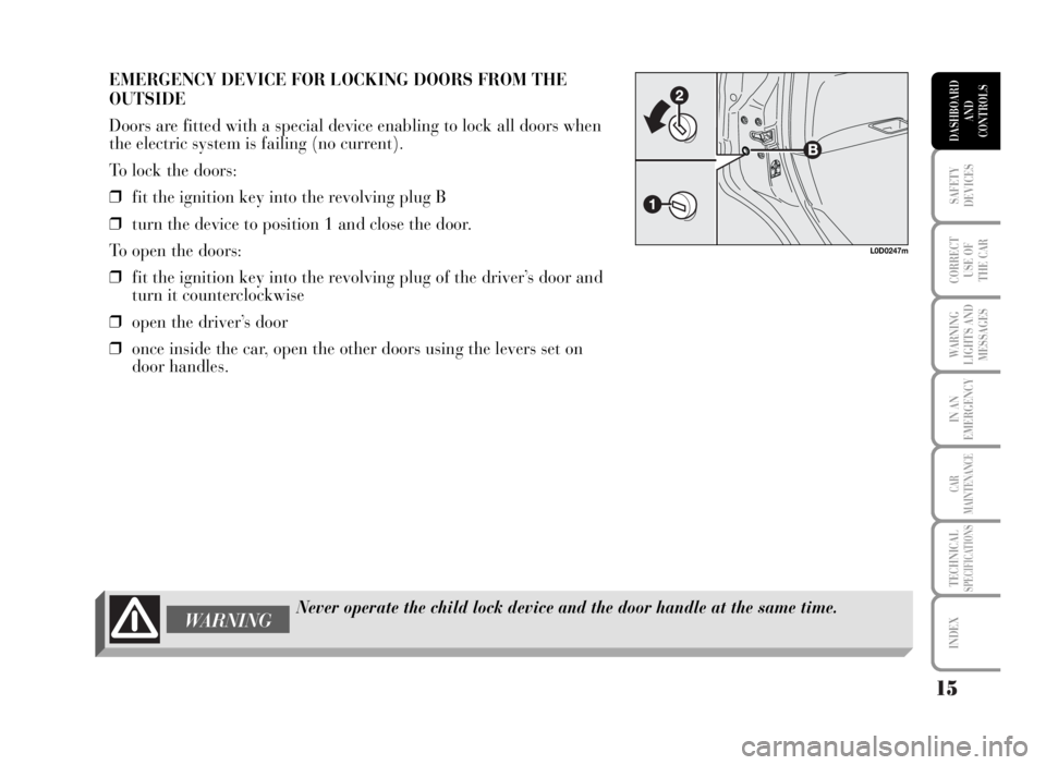
EMERGENCY DEVICE FOR LOCKING DOORS FROM THE
OUTSIDE
Doors are fitted with a special device enabling to lock all doors when
the electric system is failing (no current).
To lock the doors:
❒fit the ignition key into the revolving plug B
❒turn the device to position 1 and close the door.
To open the doors:
❒fit the ignition key into the revolving plug of the driver’s door and
turn it counterclockwise
❒open the driver’s door
❒once inside the car, open the other doors using the levers set on
door handles.
Never operate the child lock device and the door handle at the same time.WARNING
L0D0247m
Page 20 of 346

19
SAFETY
DEVICES
CORRECT
USE OF
THE CAR
WARNING
LIGHTS AND
MESSAGES
IN AN
EMERGENCY
CAR
MAINTENANCE
TECHNICALSPECIFICATIONS
INDEX
DASHBOARD
AND
CONTROLS
The main functions that can be activated with the keys (with or without remote control) are the following:
Type of key
Spare key
without
remote control
Main keywith remote
control
Direction indicators flashing
(only with key with
remote control)
Deterrence led
Pressing the pushbutton Ëenables fuel lid to be openedDoor opening
Key turning
counterclockwise
(driver’s side)
Key turning
counterclockwise
(driver’s side)
Pressing briefly
button
Ë
Two flashings
Turning off Door locking
from the outside
Key turning
clockwise
(driver’s side)
Key turning
clockwise
(driver’s side)
Pressing briefly
button
Á
One flashing
Turned on fixed for approx.
3 seconds, followed
by deterrence led flashingBoot opening
Prolonged pressing
(> 2 seconds) on button
R
Two flashings
Deterrence led flashing
Page 30 of 346

MULTIFUNCTION DISPLAY
(On two-line mode panel)
The “Multifunction display” shows all the useful information
necessary when driving, more particularly:
INFORMATION ON STANDARD SCREEN
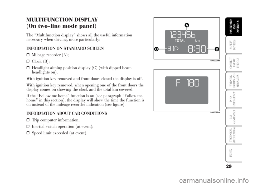
❒Mileage recorder (A);
❒Clock (B);
❒Headlight aiming position display (C) (with dipped beam
headlights on).
With ignition key removed and front doors closed the display is off.
With ignition key removed, when opening one of the front doors the
display comes on showing the clock and the total km covered.
If the “Follow me home” function is on (see paragraph “Follow me
home” in this section), the display will show the time the function is
on instead of the mileage recorder indication (see figure).
INFORMATION ABOUT CAR CONDITIONS
❒Trip computer information;
❒Inertial switch operation (at event);
❒Speed limit exceeded (at event).
29
SAFETY
DEVICES
CORRECT
USE OF
THE CAR
WARNING
LIGHTS AND
MESSAGES
IN AN
EMERGENCY
CAR
MAINTENANCE
TECHNICALSPECIFICATIONS
INDEX
DASHBOARD
AND
CONTROLS
L0D0028m
L0D0027m
Page 32 of 346

SET-UP MENU
The “Set-up Menu” enables to perform the following adjustments
and/or settings:
❒SET CLOCK
❒BUZZER VOLUME
❒SPEED LIMIT
❒SET DISTANCE UNIT.
Set clock
The car is delivered with this function set on 24 hours.
Proceed as follows for the required setting:
❒press repeatedly the MODE button until displaying “Hour”;
❒press +to increase by one minute;
❒press –to decrease by one minute.
Keeping buttons +or–pressed for a few seconds obtains automatic
fast increase or decrease, until releasing the buttons.
❒Press MODE button for over 2 seconds to confirm setting.
31
SAFETY
DEVICES
CORRECT
USE OF
THE CAR
WARNING
LIGHTS AND
MESSAGES
IN AN
EMERGENCY
CAR
MAINTENANCE
TECHNICALSPECIFICATIONS
INDEX
DASHBOARD
AND
CONTROLS
L0D0034m
Page 38 of 346

MULTIFUNCTION DISPLAY
(On three-line comfort panel)
The “Multifunction display” shows all the useful information
necessary when driving, more particularly:
INFORMATION ON STANDARD SCREEN
❒Date A.
❒Mileage recorder B.
❒Clock C.
❒External temperature D.
When the ignition key is removed only the time is displayed; when
opening one of the front doors the display comes on showing the
odometer indication.
INFORMATION ABOUT CAR CONDITIONS (at event)
❒Scheduled maintenance programme intervals.
❒ Trip computer information.
❒To adjust the intensity of the instrument dimmer/ menus/
instrument panel, sound system and automatic two-zone climate
control system display.
❒Display of failure/warning messages/function activation.
❒Display of the CITY mode (if selected).
❒Headlight aiming position display (with dipped beam headlights
on) E.
❒Symbol for possible ice on road.
37
SAFETY
DEVICES
CORRECT
USE OF
THE CAR
WARNING
LIGHTS AND
MESSAGES
IN AN
EMERGENCY
CAR
MAINTENANCE
TECHNICALSPECIFICATIONS
INDEX
DASHBOARD
AND
CONTROLS
FOH9000m
Page 40 of 346

39
SAFETY
DEVICES
CORRECT
USE OF
THE CAR
WARNING
LIGHTS AND
MESSAGES
IN AN
EMERGENCY
CAR
MAINTENANCE
TECHNICALSPECIFICATIONS
INDEX
DASHBOARD
AND
CONTROLS
SET-UP MENU
The “Set-up Menu” enables to perform the
following adjustments and/or settings using the
control buttons (see previous pages):
❒SPEED LIMIT
❒AUTOMATIC HEADLIGHT DAYLIGHT
SENSOR (where provided)
❒TRIP B ON/OFF
❒SET CLOCK
❒CLOCK MODE
❒SET DATE
❒SPEEDLOCK
❒INDEPENDENT BOOT
❒DRIVER’S DOOR UNLOCKING❒DISTANCE UNIT
❒CONSUMPTION UNIT
❒TEMPERATURE UNIT (where required)
❒LANGUAGE
❒BUZZER VOLUME
❒BUTTON VOLUME
❒S.B.R. (Seat Belt Reminder) BUZZER
REACTIVATION (*)
❒SERVICE
❒EXIT MENU
(*) This function can be displayed only after Lancia Dealership has deactivated the S.B.R. system.
Page 44 of 346

43
SAFETY
DEVICES
CORRECT
USE OF
THE CAR
WARNING
LIGHTS AND
MESSAGES
IN AN
EMERGENCY
CAR
MAINTENANCE
TECHNICALSPECIFICATIONS
INDEX
DASHBOARD
AND
CONTROLS
Is the car
moving? See
“Initial check”
Extended menu screen
only with the car
at a standstill Example of
standard screen
Menu screen
Q
NO
YES
Speed Lim.
Day Sens.
Exit MenuSpeed Lim.
Light Sensor
Trip B
Clock Adjust.
Clock Mode
Date Adjustm.
Door Lock
Indep. Boot On
Unlock Fda. On
Dist. Unit
Cons.
Temp. Unit
Lang.
Buzzer Vol.
Keys volume
Serv.
Exit Menu
Q= Press “MODE” button for less than two seconds
R= Press “MODE” button for over two seconds
Page 48 of 346

47
SAFETY
DEVICES
CORRECT
USE OF
THE CAR
WARNING
LIGHTS AND
MESSAGES
IN AN
EMERGENCY
CAR
MAINTENANCE
TECHNICALSPECIFICATIONS
INDEX
DASHBOARD
AND
CONTROLS
SET CLOCK (Clock Adjust.)
The clock can be set at car delivery.
To set the clock (hours - minutes) proceed as follows:
R R
Q Q
– + – +
R
Q
– +
R
Q
Q
See “Initial check”
and “Access to
menu screen”
Menu screen
Every press (pulse) on the +/– button increases or de-
creases by one unit. Keeping the +/– button pressed ob-
tains the automatic fast increase or decrease.
Return to menu
screen Return to previously
displayed
screen, e.g.: Return to previously
displayed
screen, e.g.:
Q= Press “MODE” button for less than two seconds
R= Press “MODE” button for over two seconds
R
Page 49 of 346

48
SAFETY
DEVICES
CORRECT
USE OF
THE CAR
WARNING
LIGHTS AND
MESSAGES
IN AN
EMERGENCY
CAR
MAINTENANCE
TECHNICALSPECIFICATIONS
INDEX
DASHBOARD
AND
CONTROLS
CLOCK MODE (Clck. Mode)
This function is used to set the clock in the 12 hour or 24 hour mode. To adjust proceed as follows:
The car is delivered with this function set to 24h.
8:30
R
Q
– + – +
R
8:30
Q Q
See “Initial check”
and “Access to
menu screen”
Menu screen
Use buttons +/– to select
12 h or 24 h mode.
Set selection flashes.
Return to menu
screen Return to menu
screenReturn to previously
displayed
screen, e.g.:
Q= Press “MODE” button for less than two seconds
R= Press “MODE” button for over two seconds
Q
Q
RR
Page 71 of 346

70
SAFETY
DEVICES
CORRECT
USE OF
THE CAR
WARNING
LIGHTS AND
MESSAGES
IN AN
EMERGENCY
CAR
MAINTENANCE
TECHNICALSPECIFICATIONS
INDEX
DASHBOARD
AND
CONTROLS
SEAT ADJUSTMENT
FRONT SEATS
Moving the seat backwards or forwards
Lift the lever A and push the seat forwards or backwards: in the
driving position the arms should rest on the rim of the steering wheel.
Always check that the seat is firmly locked in the runners by trying to
move it back and forth.
Seat height adjustment (driver’s side) (where provided)
Move repeatedly lever B upwards or downwards to achieve the
required height.
IMPORTANT Adjustment must be carried out only seated in the
driver’s seat with the car at a standstill.
Back rest angle adjustment
Move lever D as shown by the arrow, set the back rest in the required
position, then release the lever.
Lumbar adjustment (where provided)
Turn knob C clockwise or counterclockwise to increase or decrease
lumbar adjustment.
After adjustments, always check that the seat is firmly locked in the runners.
WARNING
L0D0041m
L0D0042m