Lancia Musa 2008 Owner handbook (in English)
Manufacturer: LANCIA, Model Year: 2008, Model line: Musa, Model: Lancia Musa 2008Pages: 218, PDF Size: 3.68 MB
Page 11 of 218
10
SAFETY
DEVICES
STARTING
AND
DRIVING
WARNING
LIGHTS AND
MESSAGES
IN AN
EMERGENCY
MAINTENANCE
AND CARE
TECHNICALSPECIFICATIONS
INDEX
DASHBOARD
AND CONTROLS
L0D0372m
L0D0010m
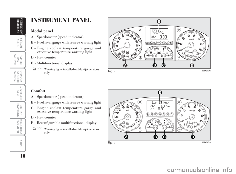
fig. 7
fig. 8
INSTRUMENT PANEL
Modal panel
A - Speedometer (speed indicator)
B – Fuel level gauge with reserve warning light
C – Engine coolant temperature gauge and
excessive temperature warning light
D - Rev. counter
E - Multifunctional display
cmWarning lights installed on Multijet versions
only
Comfort
A - Speedometer (speed indicator)
B – Fuel level gauge with reserve warning light
C – Engine coolant temperature gauge and
excessive temperature warning light
D - Rev. counter
E - Reconfigurable multifunctional display
cmWarning lights installed on Multijet versions
only
007-037 MUSA 3ed GB 12-11-2007 11:33 Pagina 10
Page 12 of 218
11
SAFETY
DEVICES
STARTING
AND
DRIVING
WARNING
LIGHTS AND
MESSAGES
IN AN
EMERGENCY
MAINTENANCE
AND CARE
TECHNICALSPECIFICATIONS
INDEX
DASHBOARD
AND CONTROLS
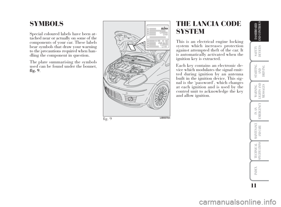
SYMBOLS
Special coloured labels have been at-
tached near or actually on some of the
components of your car. These labels
bear symbols that draw your warning
to the precautions required when han-
dling the component in question.
The plate summarising the symbols
used can be found under the bonnet,
fig. 9.
THE LANCIA CODE
SYSTEM
This is an electrical engine locking
system which increases protection
against attempted theft of the car. It
is automatically activated when the
ignition key is extracted.
Each key contains an electronic de-
vice which modulates the signal emit-
ted during ignition by an antenna
built in the ignition device. This sig-
nal is the ‘password’, which changes
at each ignition and is used by the
control unit to acknowledge the key
and allow ignition.
fig. 9L0D0375m
007-037 MUSA 3ed GB 12-11-2007 11:33 Pagina 11
Page 13 of 218
12
SAFETY
DEVICES
STARTING
AND
DRIVING
WARNING
LIGHTS AND
MESSAGES
IN AN
EMERGENCY
MAINTENANCE
AND CARE
TECHNICALSPECIFICATIONS
INDEX
DASHBOARD
AND CONTROLS
In this case, turn the key to STOP
and then back to MAR. Try with the
other keys provided if the problem
persists. If the engine will not start up
after this operation contact the
Lancia Dealership.
IMPORTANT Each key has its own
code which must be stored by the sys-
tem ECU. Contact the Lancia Dealer-
ship to have new keys (up to max.
eight) with the code stored in them.OPERATION
Each time the car is started by turn-
ing the ignition key to MAR, the Lan-
cia CODE system control unit sends
an acknowledgement code to the en-
gine control unit to deactivate the in-
hibitor. The code is sent only if the
control unit of the Lancia CODE sys-
tem has acknowledged the code re-
ceived from the key. Each time the ig-
nition key is turned to STOP, the
Lancia CODE system deactivates the
functions of the electronic engine con-
trol unit.
If, during ignition, the code is not cor-
rectly recognized, a warning light
Yis lit on the instrument panel.The electronic components
inside the key may be dam-
aged if the key is submitted
to sharp knocks.
Warning light Ycoming on
when driving
❒If the warning lightYturns on,
the system is running a self-test
(such as following a voltage fail-
ure). If the problem persists, con-
tact the Lancia Dealership.
007-037 MUSA 3ed GB 12-11-2007 11:33 Pagina 12
Page 14 of 218
13
SAFETY
DEVICES
STARTING
AND
DRIVING
WARNING
LIGHTS AND
MESSAGES
IN AN
EMERGENCY
MAINTENANCE
AND CARE
TECHNICALSPECIFICATIONS
INDEX
DASHBOARD
AND CONTROLS
THE KEY AND
DOOR LOCKING
KIT
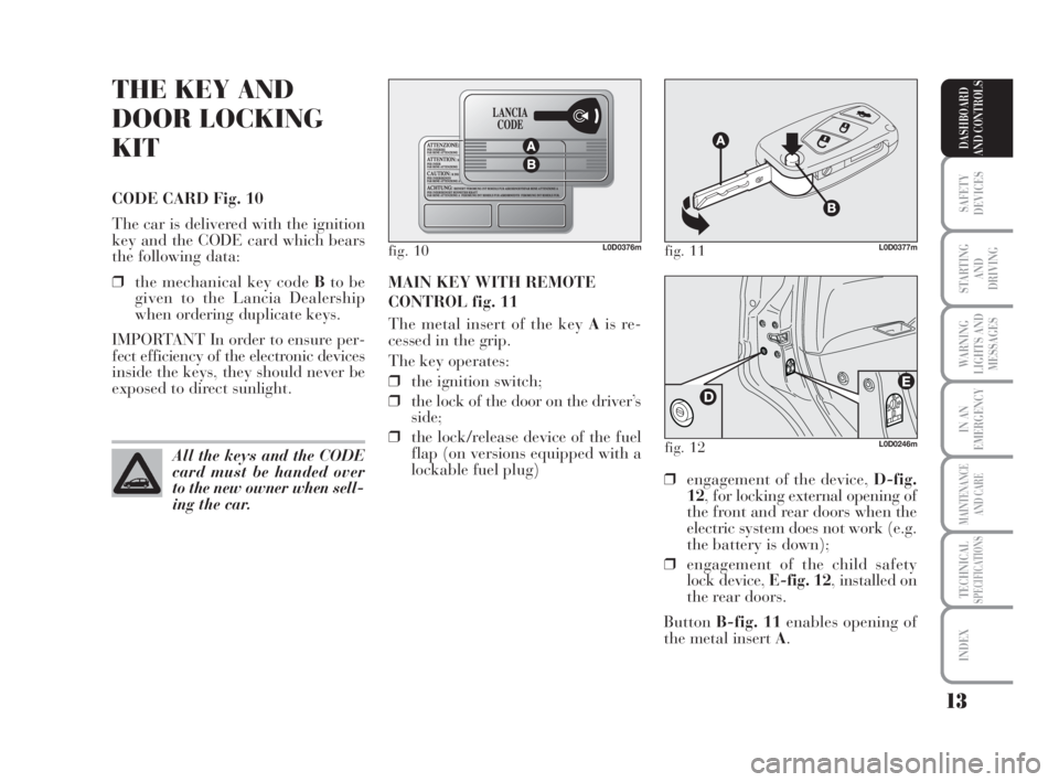
CODE CARD Fig. 10
The car is delivered with the ignition
key and the CODE card which bears
the following data:
❒the mechanical key code Bto be
given to the Lancia Dealership
when ordering duplicate keys.
IMPORTANT In order to ensure per-
fect efficiency of the electronic devices
inside the keys, they should never be
exposed to direct sunlight.MAIN KEY WITH REMOTE
CONTROL fig. 11
The metal insert of the key Ais re-
cessed in the grip.
The key operates:
❒the ignition switch;
❒the lock of the door on the driver’s
side;
❒the lock/release device of the fuel
flap (on versions equipped with a
lockable fuel plug)
fig. 10L0D0376m
All the keys and the CODE
card must be handed over
to the new owner when sell-
ing the car.
fig. 11L0D0377m
❒engagement of the device, D-fig.
12, for locking external opening of
the front and rear doors when the
electric system does not work (e.g.
the battery is down);
❒engagement of the child safety
lock device, E-fig. 12, installed on
the rear doors.
ButtonB-fig. 11enables opening of
the metal insert A.
fig. 12L0D0246m
007-037 MUSA 3ed GB 12-11-2007 11:33 Pagina 13
Page 15 of 218
14
SAFETY
DEVICES
STARTING
AND
DRIVING
WARNING
LIGHTS AND
MESSAGES
IN AN
EMERGENCY
MAINTENANCE
AND CARE
TECHNICALSPECIFICATIONS
INDEX
DASHBOARD
AND CONTROLS
IMPORTANT The remote control fre-
quency may be disturbed by radio
transmissions outside the car (e.g. cel-
lular phones, radio amateurs, etc.). If
this is the case, the remote control
may operate incorrectly.
Door and tailgate locking
Short pressure on button Á: remote
lock of doors, tailgate and fuel flap,
switching off of the internal ceiling
lights and single flashing of direction
indicators. Door and tailgate lock release
Short pressure on button Ë: lock re-
lease of doors, tailgate and fuel flap,
timed switching on of the internal
ceiling lights and double flashing of
direction indicators.
Door locks are automatically released
in case of intervention of the inertial
fuel cut-off switch.
Use the “Setup Menu” of the multi-
functional reconfigurable display (see
the dedicated paragraph in section
“Dashboard and Controls”) to set the
system in such a way that only the
door on the driver’s side is released
when pressing button Ë. To refit metal insert A, proceed as
follows:
❒Press button Band hold it pressed.
❒move the metal insert A.
❒Release button Band turn the
metal insert Auntil hearing the
click that indicates correct locking.
The button
Ëactivates the release de-
vice for doors, tailgate and fuel flap
(where provided).
The button
Áactivates the release de-
vice for doors, tailgate and fuel flap
(where provided).
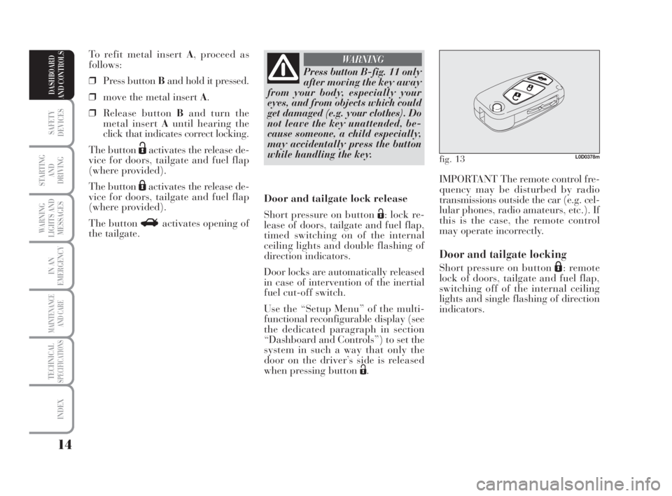
The button Ractivates opening of
the tailgate.
Press button B-fig. 11 only
after moving the key away
from your body, especially your
eyes, and from objects which could
get damaged (e.g. your clothes). Do
not leave the key unattended, be-
cause someone, a child especially,
may accidentally press the button
while handling the key.
WARNING
fig. 13L0D0378m
007-037 MUSA 3ed GB 12-11-2007 11:33 Pagina 14
Page 16 of 218
15
SAFETY
DEVICES
STARTING
AND
DRIVING
WARNING
LIGHTS AND
MESSAGES
IN AN
EMERGENCY
MAINTENANCE
AND CARE
TECHNICALSPECIFICATIONS
INDEX
DASHBOARD
AND CONTROLS
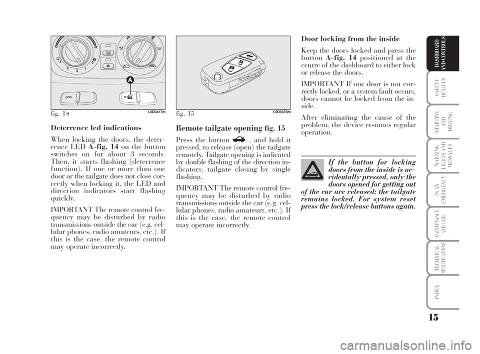
Deterrence led indications
When locking the doors, the deter-
rence LED A-fig. 14on the button
switches on for about 3 seconds.
Then, it starts flashing (deterrence
function). If one or more than one
door or the tailgate does not close cor-
rectly when locking it, the LED and
direction indicators start flashing
quickly.
IMPORTANT The remote control fre-
quency may be disturbed by radio
transmissions outside the car (e.g. cel-
lular phones, radio amateurs, etc.). If
this is the case, the remote control
may operate incorrectly.Door locking from the inside
Keep the doors locked and press the
buttonA-fig. 14positioned at the
centre of the dashboard to either lock
or release the doors.
IMPORTANT If one door is not cor-
rectly locked, or a system fault occurs,
doors cannot be locked from the in-
side.
After eliminating the cause of the
problem, the device resumes regular
operation.Remote tailgate opening fig. 15
Press the button R, and hold it
pressed, to release (open) the tailgate
remotely. Tailgate opening is indicated
by double flashing of the direction in-
dicators; tailgate closing by single
flashing.
IMPORTANT The remote control fre-
quency may be disturbed by radio
transmissions outside the car (e.g. cel-
lular phones, radio amateurs, etc.). If
this is the case, the remote control
may operate incorrectly.
fig. 14L0D0417mfig. 15L0D0378m
If the button for locking
doors from the inside is ac-
cidentally pressed, only the
doors opened for getting out
of the car are released; the tailgate
remains locked. For system reset
press the lock/release buttons again.
007-037 MUSA 3ed GB 12-11-2007 11:33 Pagina 15
Page 17 of 218
16
SAFETY
DEVICES
STARTING
AND
DRIVING
WARNING
LIGHTS AND
MESSAGES
IN AN
EMERGENCY
MAINTENANCE
AND CARE
TECHNICALSPECIFICATIONS
INDEX
DASHBOARD
AND CONTROLS
Request for additional remote
controls
The system acknowledges up to 8 re-
mote controls. Should a new remote
control be necessary, contact a Lancia
Dealership and be ready to present
the CODE card, a personal identity
document and the car’s ownership
documents.
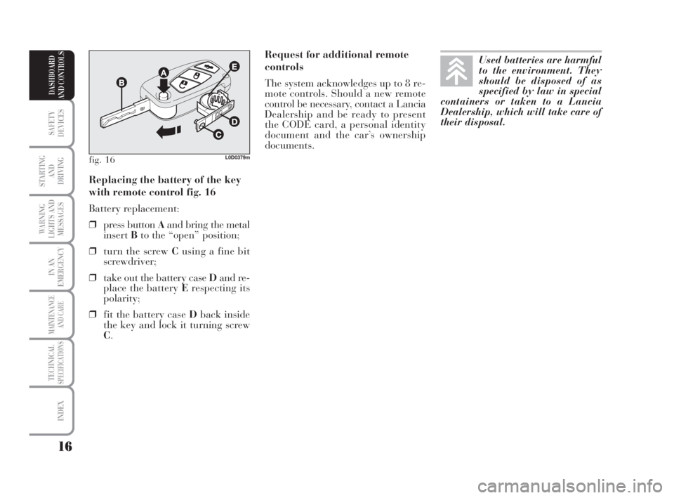
Replacing the battery of the key
with remote control fig. 16
Battery replacement:
❒press button Aand bring the metal
insertBto the “open” position;
❒turn the screw Cusing a fine bit
screwdriver;
❒take out the battery case Dand re-
place the battery Erespecting its
polarity;
❒fit the battery case Dback inside
the key and lock it turning screw
C.
fig. 16L0D0379m
Used batteries are harmful
to the environment. They
should be disposed of as
specified by law in special
containers or taken to a Lancia
Dealership, which will take care of
their disposal.
007-037 MUSA 3ed GB 12-11-2007 11:33 Pagina 16
Page 18 of 218
17
SAFETY
DEVICES
STARTING
AND
DRIVING
WARNING
LIGHTS AND
MESSAGES
IN AN
EMERGENCY
MAINTENANCE
AND CARE
TECHNICALSPECIFICATIONS
INDEX
DASHBOARD
AND CONTROLS
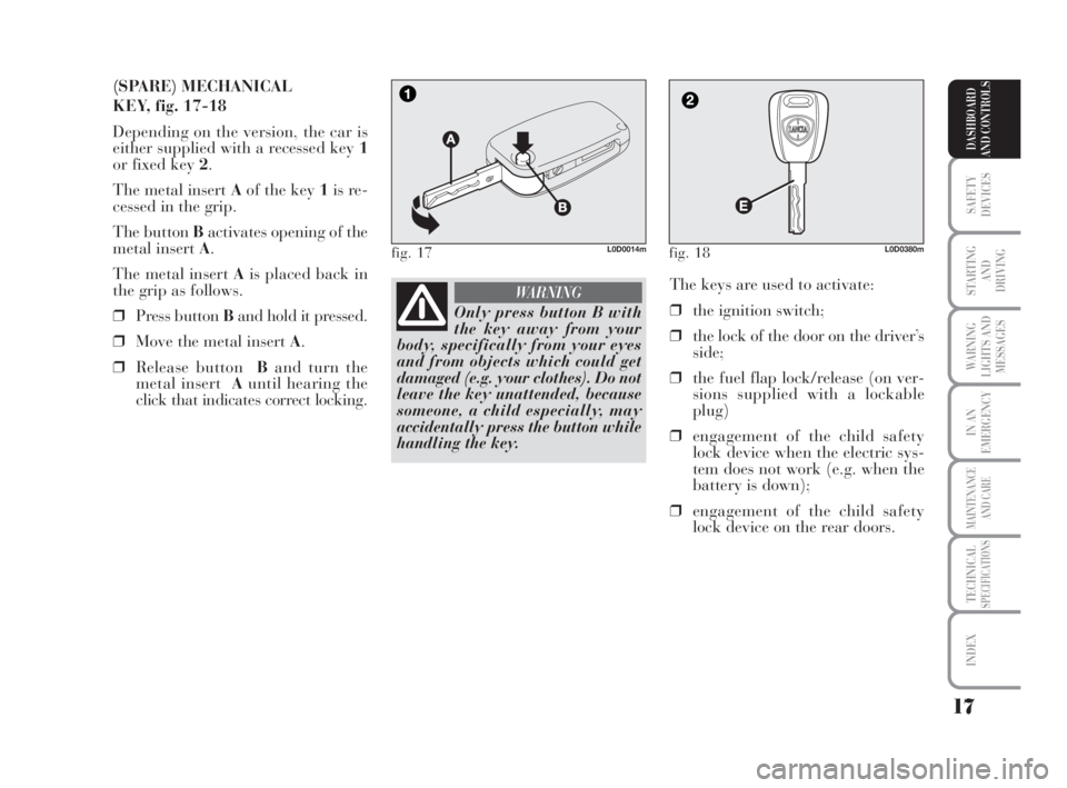
(SPARE) MECHANICAL
KEY, fig. 17-18
Depending on the version, the car is
either supplied with a recessed key 1
or fixed key 2.
The metal insert Aof the key 1is re-
cessed in the grip.
The button Bactivates opening of the
metal insert A.
The metal insert Ais placed back in
the grip as follows.
❒Press button Band hold it pressed.
❒Move the metal insert A.
❒Release buttonBand turn the
metal insertAuntil hearing the
click that indicates correct locking.The keys are used to activate:
❒the ignition switch;
❒the lock of the door on the driver’s
side;
❒the fuel flap lock/release (on ver-
sions supplied with a lockable
plug)
❒engagement of the child safety
lock device when the electric sys-
tem does not work (e.g. when the
battery is down);
❒engagement of the child safety
lock device on the rear doors.
fig. 17L0D0014mfig. 18L0D0380m
Only press button B with
the key away from your
body, specifically from your eyes
and from objects which could get
damaged (e.g. your clothes). Do not
leave the key unattended, because
someone, a child especially, may
accidentally press the button while
handling the key.
WARNING
007-037 MUSA 3ed GB 12-11-2007 11:33 Pagina 17
Page 19 of 218
18
SAFETY
DEVICES
STARTING
AND
DRIVING
WARNING
LIGHTS AND
MESSAGES
IN AN
EMERGENCY
MAINTENANCE
AND CARE
TECHNICALSPECIFICATIONS
INDEX
DASHBOARD
AND CONTROLS
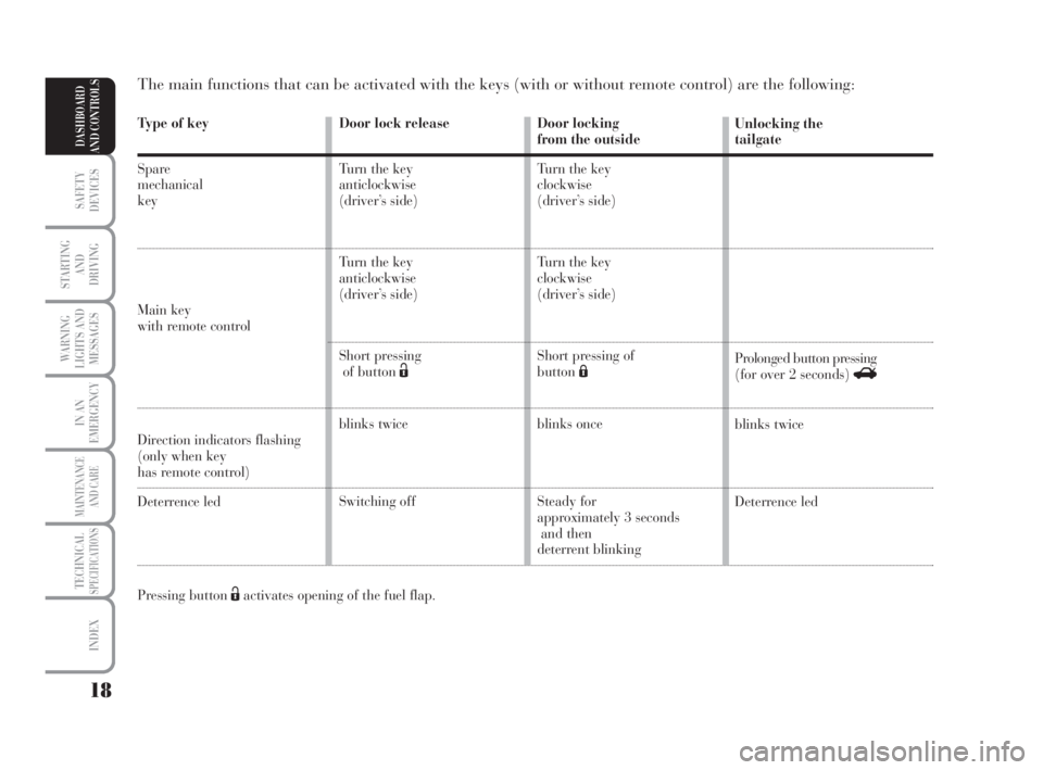
Type of key
Spare
mechanical
key
Main keywith remote control
Direction indicators flashing
(only when key
has remote control)
Deterrence led
Pressing button Ëactivates opening of the fuel flap.
The main functions that can be activated with the keys (with or without remote control) are the following:
Door locking
from the outside
Turn the key
clockwise
(driver’s side)
Turn the key
clockwise
(driver’s side)
Short pressing of
buttonÁ
blinks once
Steady for
approximately 3 seconds
and then
deterrent blinkingUnlocking the
tailgate
Prolonged button pressing
(for over 2 seconds) R
blinks twice
Deterrence led Door lock release
Turn the key
anticlockwise
(driver’s side)
Turn the key
anticlockwise
(driver’s side)
Short pressing
of button Ë
blinks twice
Switching off
007-037 MUSA 3ed GB 12-11-2007 11:33 Pagina 18
Page 20 of 218
19
SAFETY
DEVICES
STARTING
AND
DRIVING
WARNING
LIGHTS AND
MESSAGES
IN AN
EMERGENCY
MAINTENANCE
AND CARE
TECHNICALSPECIFICATIONS
INDEX
DASHBOARD
AND CONTROLS
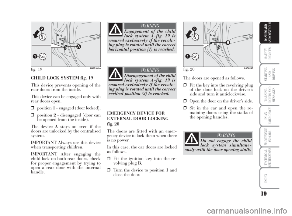
CHILD LOCK SYSTEM fig. 19
This device prevents opening of the
rear doors from the inside.
This device can be engaged only with
rear doors open.
❒position1- engaged (door locked);
❒position2- disengaged (door can
be opened from the inside).
The device Astays on even if the
doors are unlocked by the centralised
system.
IMPORTANT Always use this device
when transporting children.
IMPORTANT After engaging the
child lock on both rear doors, check
for proper engagement by trying to
open a rear door with the internal
handle.The doors are opened as follows.
❒Fit the key into the revolving plug
of the door lock on the driver’s
side and turn it anticlockwise.
❒Open the door on the driver’s side.
❒Sit in the car and open the re-
maining doors using the stalks of
the opening handles.
fig. 19L0D0101m
Engagement of the child
lock system A-fig. 19 is
ensured exclusively if the revolv-
ing plug is rotated until the correct
horizontal position (1) is reached.
WARNING
Disengagement of the child
lock system A-fig. 19 is
ensured exclusively if the revolv-
ing plug is rotated until the correct
vertical position (2) is reached.
WARNING
EMERGENCY DEVICE FOR
EXTERNAL DOOR LOCKING
fig. 20
The doors are fitted with an emer-
gency device to lock them when there
is no power.
In this case, the car doors are locked
as follows.
❒Fit the ignition key into the re-
volving plug B.
❒Turn the device to position 1and
close the door.
fig. 20L0D0247
Do not engage the child
lock system simultane-
ously with the door opening stalk.
WARNING
007-037 MUSA 3ed GB 12-11-2007 11:33 Pagina 19