climate control Lancia Musa 2008 Owner handbook (in English)
[x] Cancel search | Manufacturer: LANCIA, Model Year: 2008, Model line: Musa, Model: Lancia Musa 2008Pages: 218, PDF Size: 3.68 MB
Page 8 of 218
7
SAFETY
DEVICES
STARTING
AND
DRIVING
WARNING
LIGHTS AND
MESSAGES
IN AN
EMERGENCY
MAINTENANCE
AND CARE
TECHNICALSPECIFICATIONS
INDEX
DASHBOARD
AND CONTROLSDASHBOARD ........................................................ 8
INSTRUMENT PANEL.......................................... 10
SYMBOLS ............................................................. 11
THE LANCIA CODE SYSTEM .............................. 11
THE KEY AND DOOR LOCKING KIT ................. 13
IGNITION DEVICE .............................................. 20
INSTRUMENTS ................................................... 21
MULTIFUNCTIONAL DISPLAY
(on two-line modal panel) ...................................... 22
MULTIFUNCTIONAL DISPLAY
(on three-line modal panel).................................... 25
ADJUSTING THE SEATS ..................................... 38
HEAD RESTRAINTS ............................................ 44
ADJUSTING THE STEERING WHEEL ............... 45
REARVIEW MIRRORS .......................................... 46
HEATING/CLIMATE CONTROL SYSTEM .......... 47
MANUAL CLIMATE CONTROL SYSTEM ........... 48
AUTOMATIC CLIMATE CONTROL
SYSTEM (TWO-ZONE) ....................................... 52
EXTERNAL LIGHTS ........................................... 62
WINDOW WASHING ............................................ 64
CRUISE CONTROL ............................................. 67CEILING LIGHTS ................................................. 69
LIGHT CONTROL BUTTONS .............................. 71
FUEL CUT-OFF INERTIAL SWITCH ................... 72
INTERNAL EQUIPMENT .................................... 73
SMOKERS KIT ...................................................... 75
SUN VISORS ......................................................... 76
SUNROOF ............................................................ 76
POWER WINDOWS ............................................. 78
BOOT .................................................................... 80
BONNET ............................................................... 82
ROOF BARS .......................................................... 83
HEADLIGHTS ...................................................... 84
ABS SYSTEM ....................................................... 85
EOBD SYSTEM .................................................... 86
SOUND SYSTEM .................................................. 87
ACCESSORIES PURCHASED BY THE OWNER .. 88
“DUALDRIVE” ELECTRIC POWER
STEERING SYSTEM ............................................ 89
PARKING SENSORS ............................................ 91
REFUELLING ...................................................... 92
ENVIRONMENTAL PROTECTION ..................... 94
DASHBOARD AND CONTROLS
007-037 MUSA 3ed GB 12-11-2007 11:33 Pagina 7
Page 9 of 218
8
SAFETY
DEVICES
STARTING
AND
DRIVING
WARNING
LIGHTS AND
MESSAGES
IN AN
EMERGENCY
MAINTENANCE
AND CARE
TECHNICALSPECIFICATIONS
INDEX
DASHBOARD
AND CONTROLS
L0D0374m
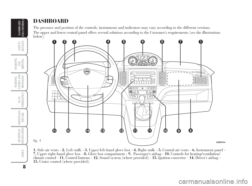
1.Side air vents - 2.Left stalk - 3.Upper left-hand glove box - 4.Right stalk - 5.Central air vents - 6.Instrument panel -
7.Upper right-hand glove box - 8.Glove box compartment - 9.Passenger’s airbag - 10.Controls for heating/ventilation/
climate control - 11.Control buttons - 12.Sound system (where provided) - 13.Ignition converter - 14.Driver’s airbag -
15.Cruise control (where provided).
DASHBOARD
The presence and position of the controls, instruments and indicators may vary according to the different versions.
The upper and lower central panel offers several solutions according to the Customer’s requirements (see the illustrations
below).
fig. 1
007-037 MUSA 3ed GB 12-11-2007 11:33 Pagina 8
Page 10 of 218
9
SAFETY
DEVICES
STARTING
AND
DRIVING
WARNING
LIGHTS AND
MESSAGES
IN AN
EMERGENCY
MAINTENANCE
AND CARE
TECHNICALSPECIFICATIONS
INDEX
DASHBOARD
AND CONTROLS
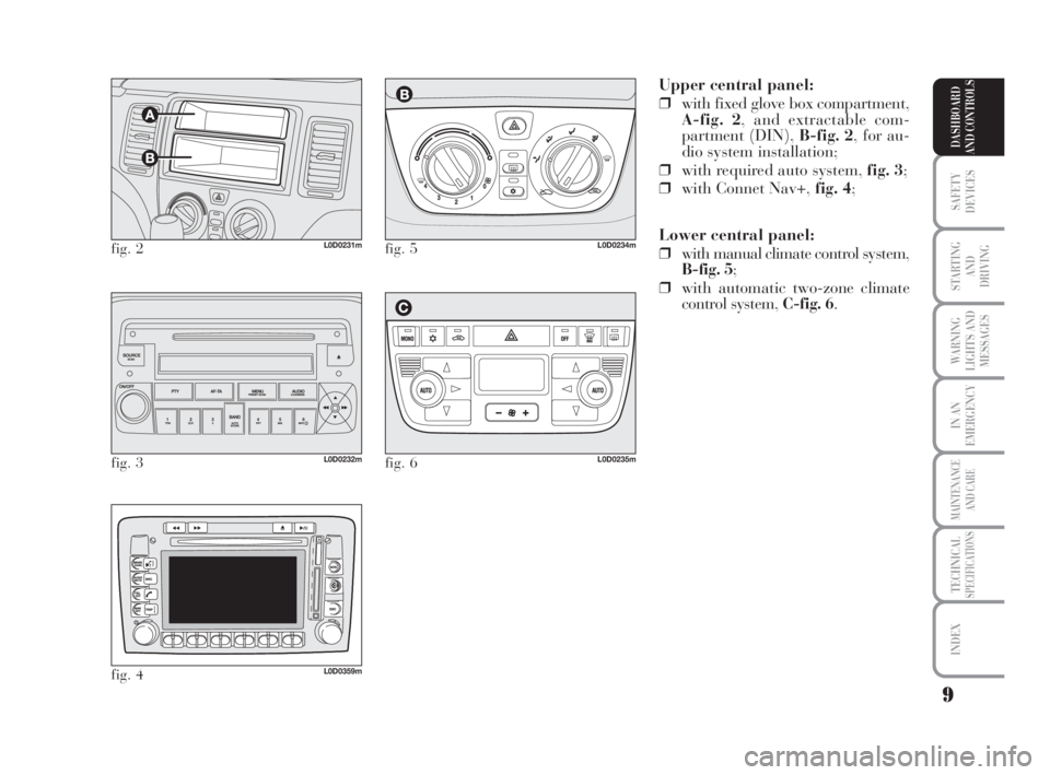
Upper central panel:
❒with fixed glove box compartment,
A-fig. 2, and extractable com-
partment (DIN), B-fig. 2, for au-
dio system installation;
❒with required auto system, fig. 3;
❒with Connet Nav+, fig. 4;
Lower central panel:
❒with manual climate control system,
B-fig. 5;
❒with automatic two-zone climate
control system, C-fig. 6.
fig. 2L0D0231m
fig. 3L0D0232m
fig. 4L0D0359m
fig. 5L0D0234m
fig. 6L0D0235m
007-037 MUSA 3ed GB 12-11-2007 11:33 Pagina 9
Page 22 of 218
21
SAFETY
DEVICES
STARTING
AND
DRIVING
WARNING
LIGHTS AND
MESSAGES
IN AN
EMERGENCY
MAINTENANCE
AND CARE
TECHNICALSPECIFICATIONS
INDEX
DASHBOARD
AND CONTROLS
INSTRUMENTS
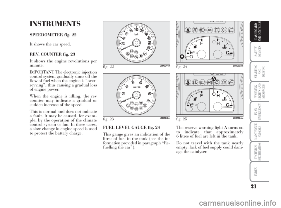
SPEEDOMETER fig. 22
It shows the car speed.
REV. COUNTER fig. 23
It shows the engine revolutions per
minute.
IMPORTANT The electronic injection
control system gradually shuts off the
flow of fuel when the engine is “over-
revving”, thus causing a gradual loss
of engine power.
When the engine is idling, the rev
counter may indicate a gradual or
sudden increase of the speed.
This is normal and does not indicate
a fault. It may be caused, for exam-
ple, by the operation of the climate
control system or fan. In these cases,
a slow change in engine speed is used
to protect the battery charge.The reserve warning light Aturns on
to indicate that approximately
6 litres of fuel are left in the tank.
Do not travel with the tank nearly
empty: lack of fuel supply could dam-
age the catalyser. FUEL LEVEL GAUGE fig. 24
This gauge gives an indication of the
litres of fuel in the tank (see the in-
formation provided in paragraph “Re-
fuelling the car”).
fig. 22L0D0241mfig. 24L0D0023m
fig. 23L0D0242mfig. 25L0D0024m
007-037 MUSA 3ed GB 12-11-2007 11:33 Pagina 21
Page 48 of 218
47
SAFETY
DEVICES
STARTING
AND
DRIVING
WARNING
LIGHTS AND
MESSAGES
IN AN
EMERGENCY
MAINTENANCE
AND CARE
TECHNICALSPECIFICATIONS
INDEX
DASHBOARD
AND CONTROLS
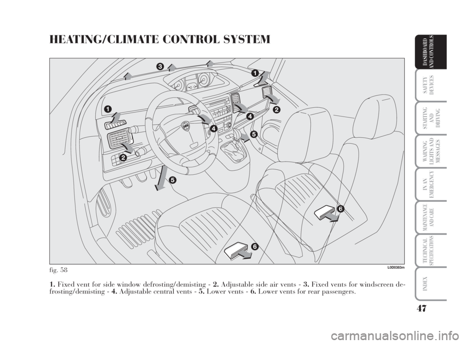
HEATING/CLIMATE CONTROL SYSTEM
fig. 58
1.Fixed vent for side window defrosting/demisting - 2.Adjustable side air vents - 3.Fixed vents for windscreen de-
frosting/demisting - 4.Adjustable central vents - 5.Lower vents - 6.Lower vents for rear passengers.
L0D0383m
038-094 MUSA 3ed GB 12-11-2007 11:35 Pagina 47
Page 49 of 218
48
SAFETY
DEVICES
STARTING
AND
DRIVING
WARNING
LIGHTS AND
MESSAGES
IN AN
EMERGENCY
MAINTENANCE
AND CARE
TECHNICALSPECIFICATIONS
INDEX
DASHBOARD
AND CONTROLS
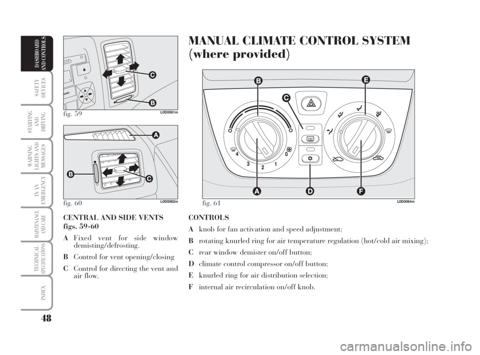
CONTROLS
Aknob for fan activation and speed adjustment;
Brotating knurled ring for air temperature regulation (hot/cold air mixing);
Crear window demister on/off button;
Dclimate control compressor on/off button;
Eknurled ring for air distribution selection;
Finternal air recirculation on/off knob.
MANUAL CLIMATE CONTROL SYSTEM
(where provided)
CENTRAL AND SIDE VENTS
figs. 59-60
AFixed vent for side window
demisting/defrosting.
BControl for vent opening/closing
CControl for directing the vent and
air flow.
fig. 59L0D0061m
fig. 60 fig. 61L0D0062mL0D0064m
038-094 MUSA 3ed GB 12-11-2007 11:35 Pagina 48
Page 51 of 218

50
SAFETY
DEVICES
STARTING
AND
DRIVING
WARNING
LIGHTS AND
MESSAGES
IN AN
EMERGENCY
MAINTENANCE
AND CARE
TECHNICALSPECIFICATIONS
INDEX
DASHBOARD
AND CONTROLS
Window demisting
In the event of considerable outside
moisture and/or rain and/or consid-
erable differences in temperature in-
side and outside the passenger com-
partment, perform the following pre-
ventive demisting procedure:
❒stop internal air recirculation by
placing knob F-fig. 61on
Ú;
❒position the rotating knurled ring
Bon the red section;
❒turn knob Aon 2;
❒position the rotating knurled ring
Eon
-with the option of shift-
ing to position ƒif the windows
do not get misted.
IMPORTANT The climate control sys-
tem is very useful to make window
demisting faster. To do this, proceed
as previously described and start the
system by pressing buttonD. FRONT WINDOW FAST
DEMISTING/DEFROSTING
(WINDSCREEN AND SIDE
WINDOWS)
Proceed as follows:
❒position the rotating knurled ring
Bon the red section;
❒turn knob Aon 4
-;
❒position the rotating knurled ring E
on
-;
❒stop internal air recirculation by
placing knob Fon
Ú.
After demisting/defrosting, operate
the controls to restore the required
comfort. FAST HEATING
Proceed as follows:
❒close all the vents on the dash-
board;
❒position the rotating knurled ring
B-fig. 61on the red section;
❒turn knob Aon 4
-;
❒position the rotating knurled ring
Eon
≈.
038-094 MUSA 3ed GB 12-11-2007 11:35 Pagina 50
Page 52 of 218

51
SAFETY
DEVICES
STARTING
AND
DRIVING
WARNING
LIGHTS AND
MESSAGES
IN AN
EMERGENCY
MAINTENANCE
AND CARE
TECHNICALSPECIFICATIONS
INDEX
DASHBOARD
AND CONTROLS
DEMISTING/DEFROSTING
OF REAR WINDOW DEMISTER
AND ELECTRICAL DOOR
MIRRORS (where provided)
Press button C-fig. 61to enable this
function. When the function is active,
a led on the button goes on.
This is a timed function, which is au-
tomatically disabled by the system af-
ter a preset time. Press button C
again to disable the function in ad-
vance.
IMPORTANT Do not affix decals on
the inside of the rear window over the
heating filaments to avoid damage
that might cause it to stop working
properly.Regulating cooling
Proceed as follows:
❒stop internal air recirculation by
placing knob F-fig. 61on
Ú;
❒turn the rotating knurled ring B
clockwise to increase the temper-
ature;
❒turn knob Aanticlockwise to re-
duce the fan speed.
SERVICING THE SYSTEM
Run the climate control system for at
least 10 minutes every month during
the winter. Have the system inspected
at a Lancia Dealership before the
summer. CLIMATE CONTROL
(cooling and de-humidification)
Proceed as follows:
❒position the rotating knurled ring
B-fig. 61on the blue section to
select the required temperature;
❒turn knob Ato the required speed;
❒position the knurled ring Eon
«;
❒position the knob Fon
…;
❒press button D
√(the LED on the
button goes on).
038-094 MUSA 3ed GB 12-11-2007 11:35 Pagina 51
Page 53 of 218
52
SAFETY
DEVICES
STARTING
AND
DRIVING
WARNING
LIGHTS AND
MESSAGES
IN AN
EMERGENCY
MAINTENANCE
AND CARE
TECHNICALSPECIFICATIONS
INDEX
DASHBOARD
AND CONTROLS
The temperature of the delivered air
is always controlled automatically de-
pending on the temperature values set
on the driver’s and front passenger’s
display (except for cases in which the
system is OFF or the compressor dis-
engaged).
The following parameters and func-
tions can be set or changed manually:
❒temperature of air on driver’s/
front passenger’s side;
❒fan speed (continuous variation);
❒air distribution on five levels (dri-
ver’s/front passenger’s side);
❒climate control compressor ON;
❒monozone/two-zone distribution
priority;
❒fast demisting/defrosting;
❒air recirculation;
❒rear window demister;
❒system deactivation. ❒compressor ON (for air
cooling/de-humidification);
❒air recirculation.
All functions may be manually
changed. In order words, you may se-
lect one or more functions and change
the parameters as required. Auto-
matic control of the manually
changed functions will be suspended:
the system will change override your
settings only for safety-related reasons
(e.g. risk of misting up).
Manual selections always have higher
priority over automatic settings and
are stored until the user switches the
system back to automatic control ex-
pect for cases in which the system in-
tervenes for particular safety-related
reasons.
You can adjust one function automat-
ically and have the automatic system
control all the others.
The amount of air delivered to the
passenger compartment depends on
the car speed, because it is regulated
by the electronic fan.AUTOMATIC
TWO-ZONE
CLIMATE
CONTROL SYSTEM
(where provided)
INTRODUCTION
The automatic two-zone climate con-
trol system adjusts the temperature
and distribution of air in the passen-
ger compartment in two zones: the
driver’s side and the passenger’s side.
Temperature is controlled on the ba-
sis of an “equivalent temperature”
principle. In other words, the system
continuously works to keep the com-
fort level inside the car constant and
to compensate for possible variations
of external conditions, including sun
radiation detected by a specific sen-
sor.
The automatically controlled para-
meters and functions are:
❒air temperature delivered to dri-
ver/front passenger vents;
❒air distribution to driver/front pas-
senger vents;
❒fan speed (continuous air flow
variation);
038-094 MUSA 3ed GB 12-11-2007 11:35 Pagina 52
Page 54 of 218

53
SAFETY
DEVICES
STARTING
AND
DRIVING
WARNING
LIGHTS AND
MESSAGES
IN AN
EMERGENCY
MAINTENANCE
AND CARE
TECHNICALSPECIFICATIONS
INDEX
DASHBOARD
AND CONTROLS
CONTROLS
A:button for activating the MONO
function (alignment of set temper-
atures);
B:climate control compressor on/off
button;
C:air recirculation on/off button;
D:climate control system information
display;
L:fan speed increase/decrease;
M:air distribution button on driver’s
side;
N:button for activating the AUTO
function (automatic operation)
and knob for setting the tempera-
ture on the driver’s side. E:climate control system off button;
F:button for activating the MAX-
DEFfunction (fast front window
defrosting/demisting);
G:rear window demister on/off but-
ton;
H:button for activating the AUTO
function (automatic operation)
and knob for setting the tempera-
ture on the passenger’s side;
I:air distribution button on passen-
ger’s side;
fig. 62L0D0065m
038-094 MUSA 3ed GB 12-11-2007 11:35 Pagina 53