engine Lancia Musa 2009 Owner handbook (in English)
[x] Cancel search | Manufacturer: LANCIA, Model Year: 2009, Model line: Musa, Model: Lancia Musa 2009Pages: 218, PDF Size: 3.7 MB
Page 34 of 218
33
SAFETY
DEVICES
STARTING
AND
DRIVING
WARNING
LIGHTS AND
MESSAGES
IN AN
EMERGENCY
MAINTENANCE
AND CARE
TECHNICALSPECIFICATIONS
INDEX
DASHBOARD
AND CONTROLS
Adjusting the button volume
(Button Vol.)
This function enables setting the vol-
ume of the roger-beep accompanying
the activation of buttons MODE,+
and–according to 8 levels.
To adjust the desired volume proceed
as follows:
– briefly press button MODE: the pre-
viously set volume “level” starts flash-
ing on the display;
– press button +or–to set the volume
level;
– briefly press button MODEto go
back to the menu screen or press the
button for a prolonged time to go
back to the standard screen without
storing the settings.
S.B.R. buzzer reactivation
(Belt Buzzer) (where provided)
This function can only be displayed
after Lancia Dealership has deacti-
vated the S.B.R. system (see para-
graph “S.B.R. system” in section
“Safety devices”).The indications will appear more fre-
quently when there are 200 km left.
For 1.3 Multijet versions refer to the
instructions provided in the “Sched-
uled Servicing Plan” in section “Car
Maintenance” for air filter, engine oil
and engine oil filter replacement. The
indication will appear in kilometres or
miles according to the unit settings.
When the next scheduled servicing is
near, the message “Service” will ap-
pear on the display followed by the
number of kilometres or miles or days
left before servicing when the key is
turned to MAR. The “Scheduled Ser-
vicing” message shows information in
either kilometres (km) or miles (mi)
or in days (dd) depending on the
deadline showing up first. Go to the
Lancia Dealership where the servic-
ing operations envisaged in the
“Scheduled Service Plan” or “Yearly
Inspection Plan” will be performed
and the message will be reset. Scheduled Servicing (Service)
This function enables viewing of in-
formation on proper car servicing de-
pending on the kilometres travelled or
daily intervals.
This information is consulted as fol-
lows:
– briefly press button MODE: the dis-
play shows service requirements in
km or mi according to the previous
setting (see paragraph “Distance
unit”);
– press button +or–to view the ser-
vice interval in days;
– briefly press button MODEto go
back to the menu screen or press the
button for a prolonged time to go back
to the standard screen.
NOTE According to the “Scheduled
Servicing Plan” the car must be ser-
viced every 20,000 km (or equivalent
mileage) or on a yearly basis. This
message appears automatically when
the key is positioned on MARafter
travelling for 2,000 km (or equivalent
mileage) or 30 days after the dead-
line. It appears every 200 km (or
equivalent mileage) or 3 days.
007-037 MUSA 1ed GB 10-07-2008 9:36 Pagina 33
Page 37 of 218
36
SAFETY
DEVICES
STARTING
AND
DRIVING
WARNING
LIGHTS AND
MESSAGES
IN AN
EMERGENCY
MAINTENANCE
AND CARE
TECHNICALSPECIFICATIONS
INDEX
DASHBOARD
AND CONTROLS
New mission
The new mission begins after:
– “manual” resetting by the user, by
pressing the relevant button;
– “automatic” resetting, when the
“Trip distance” reaches 9999.9 km or
when the “Travel time” reaches 99.59
(99 hours and 59 minutes);
– disconnection/reconnection of the
battery.
IMPORTANT The reset operations
performed after the “General Trip”
message appears are used to also re-
set the “Trip B”, which, on its turn, is
used to reset the values of the corre-
sponding function. Travel time
This value shows the time elapsed
since the start of a new mission.
IMPORTANT If information is not
available, the message “----” will ap-
pear instead of the Trip Computer
values. Displaying of the values will
be resumed regularly when normal
operation is restored without resetting
the values displayed before the failure
nor starting a new mission.
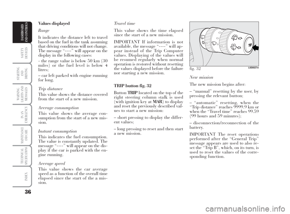
TRIP button fig. 32
ButtonTRIPlocated on the top of the
right steering column stalk is used
(with ignition key at MAR) to display
and reset the previously described val-
ues to start a new mission:
– short pressing to display the differ-
ent values;
– long pressing to reset and then start
a new mission. Values displayed
Range
It indicates the distance left to travel
based on the fuel in the tank assuming
that driving conditions will not change.
The message “----” will appear on the
display in the following cases:
- the range value is below 50 km (30
miles) or the fuel level is below 4
litres;
– car left parked with engine running
for long.
Trip distance
This value shows the distance covered
from the start of a new mission.
Average consumption
This value shows the average con-
sumption from the start of a new mis-
sion.
Instant consumption
This indicates the fuel consumption.
The value is constantly updated. The
message “----” will appear on the dis-
play if the car is parked with the en-
gine running.
Average speed
This value shows the car average
speed as a function of the overall time
elapsed since the start of the a mis-
sion.
fig. 32L0D0027m
007-037 MUSA 1ed GB 10-07-2008 9:36 Pagina 36
Page 46 of 218
45
SAFETY
DEVICES
STARTING
AND
DRIVING
WARNING
LIGHTS AND
MESSAGES
IN AN
EMERGENCY
MAINTENANCE
AND CARE
TECHNICALSPECIFICATIONS
INDEX
DASHBOARD
AND CONTROLS
ADJUSTING
THE STEERING
WHEEL
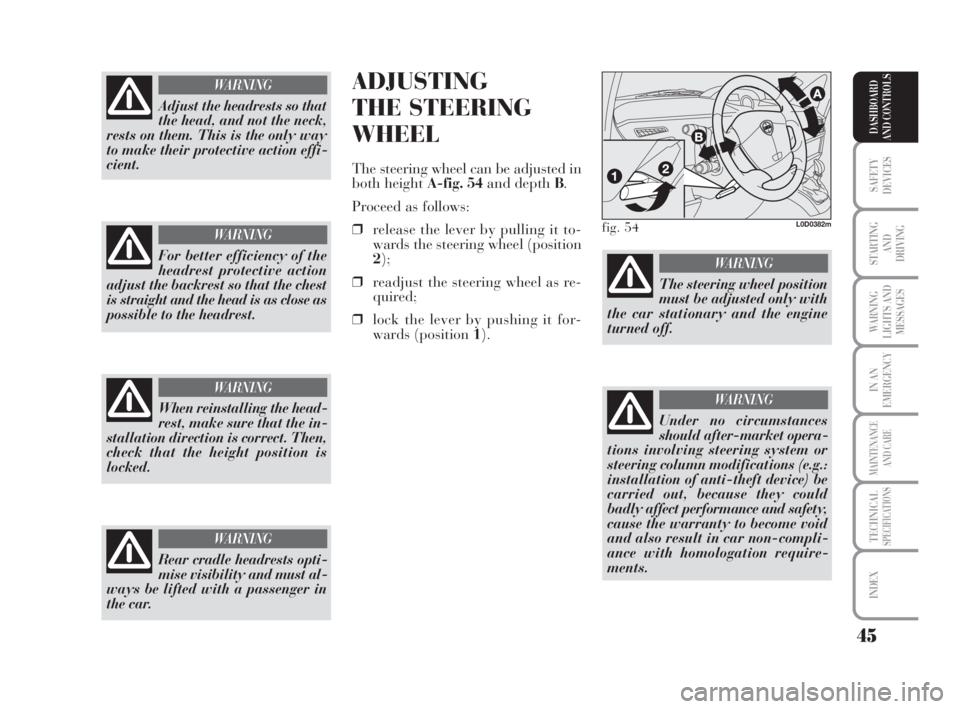
The steering wheel can be adjusted in
both height A-fig. 54and depth B.
Proceed as follows:
❒release the lever by pulling it to-
wards the steering wheel (position
2);
❒readjust the steering wheel as re-
quired;
❒lock the lever by pushing it for-
wards (position 1).
Rear cradle headrests opti-
mise visibility and must al-
ways be lifted with a passenger in
the car.
WARNING
fig. 54L0D0382m
The steering wheel position
must be adjusted only with
the car stationary and the engine
turned off.
WARNING
Under no circumstances
should after-market opera-
tions involving steering system or
steering column modifications (e.g.:
installation of anti-theft device) be
carried out, because they could
badly affect performance and safety,
cause the warranty to become void
and also result in car non-compli-
ance with homologation require-
ments.
WARNING
Adjust the headrests so that
the head, and not the neck,
rests on them. This is the only way
to make their protective action effi-
cient.
WARNING
For better efficiency of the
headrest protective action
adjust the backrest so that the chest
is straight and the head is as close as
possible to the headrest.
WARNING
When reinstalling the head-
rest, make sure that the in-
stallation direction is correct. Then,
check that the height position is
locked.
WARNING
038-094 MUSA 1ed GB 11-07-2008 14:10 Pagina 45
Page 61 of 218
60
SAFETY
DEVICES
STARTING
AND
DRIVING
WARNING
LIGHTS AND
MESSAGES
IN AN
EMERGENCY
MAINTENANCE
AND CARE
TECHNICALSPECIFICATIONS
INDEX
DASHBOARD
AND CONTROLS
IMPORTANT The fast window
demisting/defrosting function remains
engaged for approx. 3 minutes start-
ing from the time when the engine
coolant exceeds 50°C (petrol versions)
or 35°C (Multijet versions).
When this function is active, the LED
of the corresponding button switches
on and that of the rear window
demister. The text FULL AUTOgoes
off on the display.
You can only adjust the fan speed and
switch the rear window demister off
manually when this function is active.
To restore operating conditions before
this function is activated, press but-
tonF, the air recirculation button C,
the compressor button Bor button
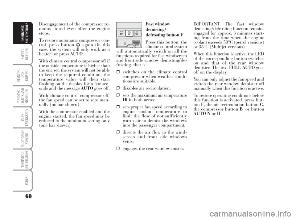
AUTO NorH. Fast window
demisting/
defrosting button F
Press this button: the
climate control system
will automatically switch on all the
functions required for fast windscreen
and front side window demisting/de-
frosting, that is:
❒switches on the climate control
compressor when weather condi-
tions are suitable;
❒disables air recirculation;
❒sets the maximum air temperature
HIin both areas;
❒sets proper fan speed according to
engine coolant temperature to
limit the flow of not sufficiently
warm air to demist the windows
into the passenger compartment;
❒directs the air flow to the wind-
screen and front side windows
vents;
❒engages the rear window mister.Disengagement of the compressor re-
mains stored even after the engine
stops.
To restore automatic compressor con-
trol, press button
√again (in this
case, the system will only work as a
heater) or press AUTO.
With climate control compressor off if
the outside temperature is higher than
the one set, the system will not be able
to keep the required condition, the
temperature value will then start
flashing on the display for a few sec-
onds and the message AUTOgoes off.
With climate control compressor off,
the fan speed can be set to zero man-
ually (no bar shown).
With the compressor enabled and the
engine started, the fan speed may be
reduced to the minimum setting only
(one bar shown).
038-094 MUSA 1ed GB 11-07-2008 14:10 Pagina 60
Page 62 of 218
61
SAFETY
DEVICES
STARTING
AND
DRIVING
WARNING
LIGHTS AND
MESSAGES
IN AN
EMERGENCY
MAINTENANCE
AND CARE
TECHNICALSPECIFICATIONS
INDEX
DASHBOARD
AND CONTROLS
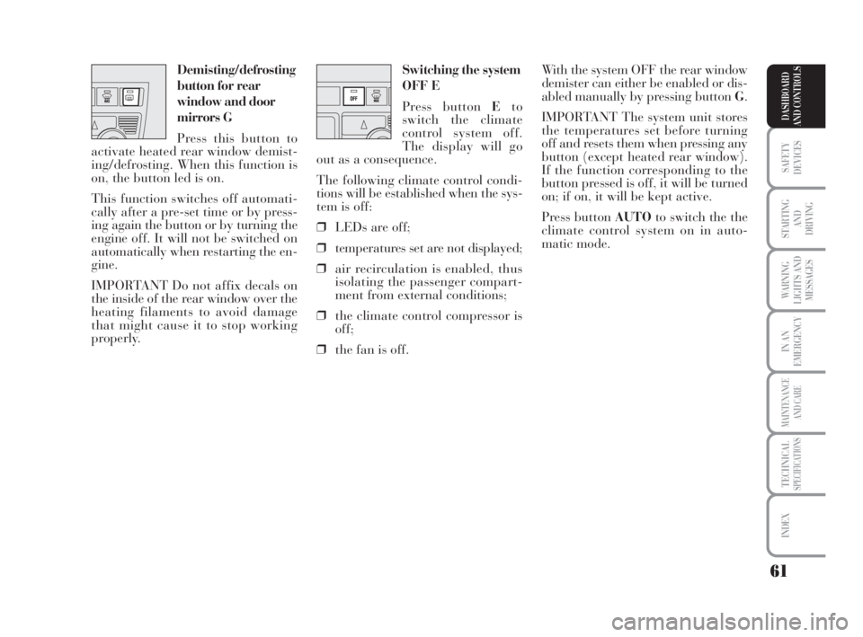
Switching the system
OFF E
Press button Eto
switch the climate
control system off.
The display will go
out as a consequence.
The following climate control condi-
tions will be established when the sys-
tem is off:
❒LEDs are off;
❒temperatures set are not displayed;
❒air recirculation is enabled, thus
isolating the passenger compart-
ment from external conditions;
❒the climate control compressor is
off;
❒the fan is off.With the system OFF the rear window
demister can either be enabled or dis-
abled manually by pressing button G.
IMPORTANT The system unit stores
the temperatures set before turning
off and resets them when pressing any
button (except heated rear window).
If the function corresponding to the
button pressed is off, it will be turned
on; if on, it will be kept active.
Press button AUTOto switch the the
climate control system on in auto-
matic mode. Demisting/defrosting
button for rear
window and door
mirrors G
Press this button to
activate heated rear window demist-
ing/defrosting. When this function is
on, the button led is on.
This function switches off automati-
cally after a pre-set time or by press-
ing again the button or by turning the
engine off. It will not be switched on
automatically when restarting the en-
gine.
IMPORTANT Do not affix decals on
the inside of the rear window over the
heating filaments to avoid damage
that might cause it to stop working
properly.
038-094 MUSA 1ed GB 11-07-2008 14:10 Pagina 61
Page 64 of 218
63
SAFETY
DEVICES
STARTING
AND
DRIVING
WARNING
LIGHTS AND
MESSAGES
IN AN
EMERGENCY
MAINTENANCE
AND CARE
TECHNICALSPECIFICATIONS
INDEX
DASHBOARD
AND CONTROLS
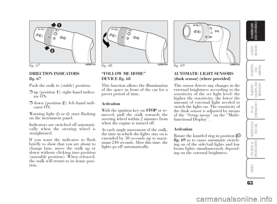
DIRECTION INDICATORS
fig. 67
Push the stalk to (stable) position:
❒up (position 1): right-hand indica-
tor ON;
❒down (position 2): left-hand indi-
cator ON.
Warning light
ForDstart flashing
on the instrument panel.
Indicators are switched off automati-
cally when the steering wheel is
straightened.
If you want the indicator to flash
briefly to show that you are about to
change lane, move the stalk up or
down without clicking into position
(unstable position). When released,
the stalk will return to its home posi-
tion.AUTOMATIC LIGHT SENSORS
(dusk sensor) (where provided)
This sensor detects any changes in the
external brightness according to the
sensitivity of the set light level: the
higher the sensitivity, the lower the
amount of external light needed to
switch the lights on. The sensitivity of
the dusk sensor is adjusted by means
of the “Setup menu” on the “Multi-
functional Display”.
Activation
Rotate the knurled ring in position
2A
fig. 69as to cause automatic switch-
ing on of the side/tail lights and low
beam lights simultaneously depend-
ing on the external brightness. “FOLLOW ME HOME”
DEVICE fig. 68
This function allows the illumination
of the space in front of the car for a
preset period of time.
Activation
With the ignition key on STOPor re-
moved, pull the stalk towards the
steering wheel within 2 minutes from
when the engine is turned off.
At each single movement of the stalk,
the time in which the lights stay on is
extended by 30 seconds up to maxi-
mum 210 seconds. After this time, the
lights go off automatically.
fig. 67L0D0071mfig. 68L0D0070mfig. 69L0D0072m
038-094 MUSA 1ed GB 11-07-2008 14:10 Pagina 63
Page 70 of 218
69
SAFETY
DEVICES
STARTING
AND
DRIVING
WARNING
LIGHTS AND
MESSAGES
IN AN
EMERGENCY
MAINTENANCE
AND CARE
TECHNICALSPECIFICATIONS
INDEX
DASHBOARD
AND CONTROLS
LIGHTS
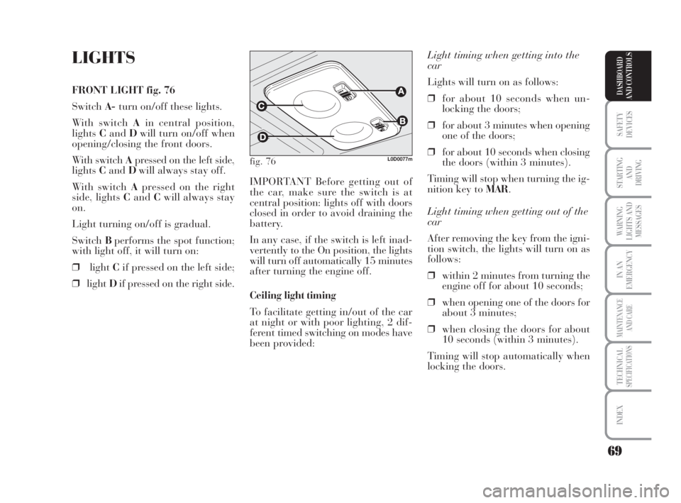
FRONT LIGHT fig. 76
SwitchA-turn on/off these lights.
With switch Ain central position,
lightsCandDwill turn on/off when
opening/closing the front doors.
With switch Apressed on the left side,
lightsCandDwill always stay off.
With switch Apressed on the right
side, lights CandCwill always stay
on.
Light turning on/off is gradual.
SwitchBperforms the spot function;
with light off, it will turn on:
❒lightCif pressed on the left side;
❒lightDif pressed on the right side.Light timing when getting into the
car
Lights will turn on as follows:
❒for about 10 seconds when un-
locking the doors;
❒for about 3 minutes when opening
one of the doors;
❒for about 10 seconds when closing
the doors (within 3 minutes).
Timing will stop when turning the ig-
nition key to MAR.
Light timing when getting out of the
car
After removing the key from the igni-
tion switch, the lights will turn on as
follows:
❒within 2 minutes from turning the
engine off for about 10 seconds;
❒when opening one of the doors for
about 3 minutes;
❒when closing the doors for about
10 seconds (within 3 minutes).
Timing will stop automatically when
locking the doors. IMPORTANT Before getting out of
the car, make sure the switch is at
central position: lights off with doors
closed in order to avoid draining the
battery.
In any case, if the switch is left inad-
vertently to the On position, the lights
will turn off automatically 15 minutes
after turning the engine off.
Ceiling light timing
To facilitate getting in/out of the car
at night or with poor lighting, 2 dif-
ferent timed switching on modes have
been provided:
fig. 76L0D0077m
038-094 MUSA 1ed GB 11-07-2008 14:10 Pagina 69
Page 71 of 218
70
SAFETY
DEVICES
STARTING
AND
DRIVING
WARNING
LIGHTS AND
MESSAGES
IN AN
EMERGENCY
MAINTENANCE
AND CARE
TECHNICALSPECIFICATIONS
INDEX
DASHBOARD
AND CONTROLS
Light timing when getting out of the
car
After removing the key from the igni-
tion switch, the lights will turn on as
follows:
❒within 2 minutes from turning the
engine off for about 10 seconds;
❒when opening one of the doors for
about 3 minutes;
❒when closing the doors for about
10 seconds (within 3 minutes).
Timing will stop automatically when
locking the doors. Light timing (where provided)
To facilitate getting in/out of the car
at night or with poor lighting, 2 dif-
ferent timed switching on modes have
been provided:
Light timing when getting into the
car
Lights will turn on as follows:
❒for about 10 seconds when un-
locking the doors;
❒for about 3 minutes when opening
one of the doors;
❒for about 10 seconds when closing
the doors (within 3 minutes).
Timing will stop when turning the ig-
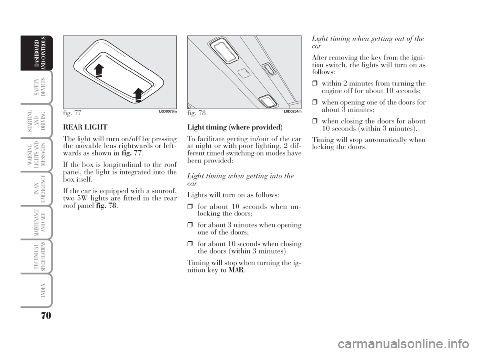
nition key to MAR. REAR LIGHT
The light will turn on/off by pressing
the movable lens rightwards or left-
wards as shown in fig. 77.
If the box is longitudinal to the roof
panel, the light is integrated into the
box itself.
If the car is equipped with a sunroof,
two 5W lights are fitted in the rear
roof panel fig. 78.
fig. 77L0D0078mfig. 78L0D0254m
038-094 MUSA 1ed GB 11-07-2008 14:10 Pagina 70
Page 73 of 218
72
SAFETY
DEVICES
STARTING
AND
DRIVING
WARNING
LIGHTS AND
MESSAGES
IN AN
EMERGENCY
MAINTENANCE
AND CARE
TECHNICALSPECIFICATIONS
INDEX
DASHBOARD
AND CONTROLS
INERTIAL FUEL
CUT-OFF SWITCH
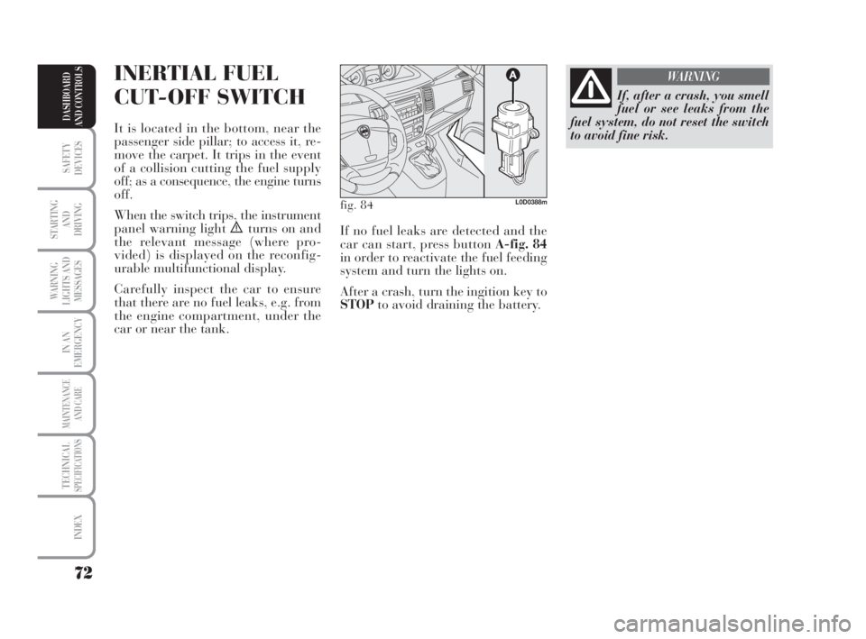
It is located in the bottom, near the
passenger side pillar; to access it, re-
move the carpet. It trips in the event
of a collision cutting the fuel supply
off; as a consequence, the engine turns
off.
When the switch trips, the instrument
panel warning light
èturns on and
the relevant message (where pro-
vided) is displayed on the reconfig-
urable multifunctional display.
Carefully inspect the car to ensure
that there are no fuel leaks, e.g. from
the engine compartment, under the
car or near the tank.
If, after a crash, you smell
fuel or see leaks from the
fuel system, do not reset the switch
to avoid fine risk.
WARNING
fig. 84L0D0388m
If no fuel leaks are detected and the
car can start, press button A-fig. 84
in order to reactivate the fuel feeding
system and turn the lights on.
After a crash, turn the ingition key to
STOPto avoid draining the battery.
038-094 MUSA 1ed GB 11-07-2008 14:10 Pagina 72
Page 84 of 218
83
SAFETY
DEVICES
STARTING
AND
DRIVING
WARNING
LIGHTS AND
MESSAGES
IN AN
EMERGENCY
MAINTENANCE
AND CARE
TECHNICALSPECIFICATIONS
INDEX
DASHBOARD
AND CONTROLS
TO CLOSE fig. 112
Proceed as follows:
❒hold the bonnet up with one hand
and with the other remove rod C
from seat and fit it back into its
catchD;
❒lower the bonnet to approximately
20 centimetres from the engine
compartment and let it drop.
Make sure that the bonnet is com-
pletely closed and not only fas-
tened by the safety catch by trying
to open it. If it is not perfectly
closed, open the bonnet and repeat
the procedure. Do not simply press
it.
IMPORTANT Always check that the
bonnet is closed properly to avoid its
opening while the car is travelling.ROOF BARS
(where provided)
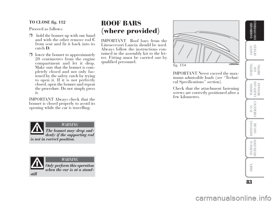
IMPORTANT Roof bars from the
Lineaccesori Lancia should be used.
Always follow the instructions con-
tained in the assembly kit to the let-
ter. Fitting must be carried out by
qualified personnel.
The bonnet may drop sud-
denly if the supporting rod
is not in correct position.
WARNING
Only perform this operation
when the car is at a stand-
still
WARNING
fig. 114L0D0248m
IMPORTANT Never exceed the max-
imum admissible loads (see “Techni-
cal Specifications” section).
Check that the attachment fastening
screws are correctly positioned after a
few kilometres.
038-094 MUSA 1ed GB 11-07-2008 14:10 Pagina 83