lock Lancia Musa 2010 Owner handbook (in English)
[x] Cancel search | Manufacturer: LANCIA, Model Year: 2010, Model line: Musa, Model: Lancia Musa 2010Pages: 218, PDF Size: 3.71 MB
Page 56 of 218
55
SAFETY
STARTING
AND DRIVING
WARNING
LIGHTS AND
MESSAGES
IN AN
EMERGENCY
MAINTENANCE
AND CARE
TECHNICAL
SPECIFICA-
TIONS
INDEX
DASHBOARD
AND
CONTROLS
This function may be used to heat up
the passenger compartment as fast as
possible and exploit the system po-
tential to the maximum. The function
uses the maximum coolant tempera-
ture while air and fan speed distribu-
tion are managed by the system ac-
cording to conditions.
Specifically, if the heating fluid is not
warm enough, the fan will not start
up at the maximum speed immedi-
ately to limit introducing excessively
cool air into the passenger compart-
ment.
All manual settings will be allowed
when this function is on.
To switch the function off, simply turn
the temperature knob anticlockwise
and set the required temperature.
❒LOfunction (maximum cooling):
select by turning the temperature
knob anticlockwise under the mini-
mum value (16 °C). It can be oper-
ated from either by the driver or by
the front passenger (by selecting the
MONOfunction). This function is used to adjust the
temperature in the passenger com-
partment when the driver only is in
the car.
To go back to separate air and tem-
perature distribution in the two zones
of the passenger compartment, sim-
ply turn the knobs Hor press (A-
MONO) when the LED on the button
is on.
Turn the knobs either all to the right
or all to the left to the extreme HIor
LOpositions to use the maximum
heating or maximum cooling func-
tions:
❒HIfunction (maximum heating):
select by turning the temperature
knob clockwise over the maximum
value (32 °C). It can be operated from
either by the driver or by the front
passenger (by selecting the MONO
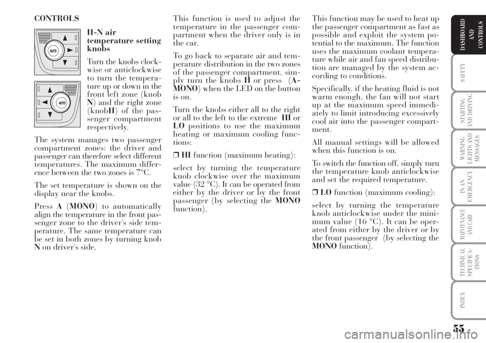
function). CONTROLS
H-N air
temperature setting
knobs
Turn the knobs clock-
wise or anticlockwise
to turn the tempera-
ture up or down in the
front left zone (knob
N) and the right zone
(knobH) of the pas-
senger compartment
respectively.
The system manages two passenger
compartment zones: the driver and
passenger can therefore select different
temperatures. The maximum differ-
ence between the two zones is 7°C.
The set temperature is shown on the
display near the knobs.
Press A(MONO) to automatically
align the temperature in the front pas-
senger zone to the driver’s side tem-
perature. The same temperature can
be set in both zones by turning knob
Non driver’s side.
Page 57 of 218
56
SAFETY
STARTING
AND DRIVING
WARNING
LIGHTS AND
MESSAGES
IN AN
EMERGENCY
MAINTENANCE
AND CARE
TECHNICAL
SPECIFICA-
TIONS
INDEX
DASHBOARD
AND
CONTROLS
˙
▼Air flow between foot well vents
(hotter air) and central and side
dashboard vents (cooler air). This
distribution is particularly useful
in spring and autumn on a sunny
day.
▲
▼Air flow distributed between foot
well vents and windscreen and front
side window defrosting/demisting
vents. This allows an adequate
warming of the passenger com-
partment and prevents the win-
dows from misting up. This function may be used to cool
down the passenger compartment as
fast as possible and exploit the system
potential to the maximum. The func-
tion activates air recirculation and the
climate control compressor, air distri-
bution and fan speed are managed by
the system according to environmen-
tal conditions. All manual settings will
be allowed when this function is on.
To switch the function off, simply turn
the temperature knob anticlockwise
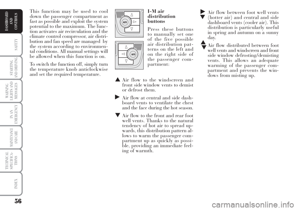
and set the required temperature.I-M air
distribution
buttons
Press these buttons
to manually set one
of the five possible
air distribution pat-
terns on the left and
on the right side of
the passenger com-
partment:
▲Air flow to the windscreen and
front side window vents to demist
or defrost them.
˙Air flow at central and side dash-
board vents to ventilate the chest
and the face during the hot season.
▼Air flow to the front and rear foot
well vents. Thanks to the natural
tendency of hot air to spread up-
wards, this distribution pattern al-
lows to warm the passenger com-
partment up as quickly as possi-
ble, providing an immediate feel-
ing of warmth.
Page 70 of 218
69
SAFETY
STARTING
AND DRIVING
WARNING
LIGHTS AND
MESSAGES
IN AN
EMERGENCY
MAINTENANCE
AND CARE
TECHNICAL
SPECIFICA-
TIONS
INDEX
DASHBOARD
AND
CONTROLS
CEILING LIGHTS
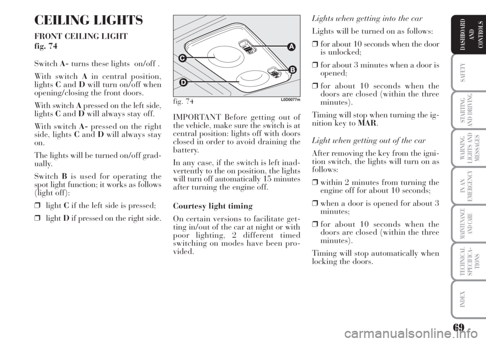
FRONT CEILING LIGHT
fig. 74
SwitchA-turns these lights on/off .
With switch Ain central position,
lightsCandDwill turn on/off when
opening/closing the front doors.
With switch Apressed on the left side,
lightsCandDwill always stay off.
With switch A-pressed on the right
side, lights CandDwill always stay
on.
The lights will be turned on/off grad-
ually.
SwitchBis used for operating the
spot light function; it works as follows
(light off):
❒lightCif the left side is pressed;
❒lightDif pressed on the right side.Lights when getting into the car
Lights will be turned on as follows:
❒for about 10 seconds when the door
is unlocked;
❒for about 3 minutes when a door is
opened;
❒for about 10 seconds when the
doors are closed (within the three
minutes).
Timing will stop when turning the ig-
nition key to MAR.
Light when getting out of the car
After removing the key from the igni-
tion switch, the lights will turn on as
follows:
❒within 2 minutes from turning the
engine off for about 10 seconds;
❒when a door is opened for about 3
minutes;
❒for about 10 seconds when the
doors are closed (within the three
minutes).
Timing will stop automatically when
locking the doors. IMPORTANT Before getting out of
the vehicle, make sure the switch is at
central position: lights off with doors
closed in order to avoid draining the
battery.
In any case, if the switch is left inad-
vertently to the on position, the lights
will turn off automatically 15 minutes
after turning the engine off.
Courtesy light timing
On certain versions to facilitate get-
ting in/out of the car at night or with
poor lighting, 2 different timed
switching on modes have been pro-
vided.
fig. 74L0D0077m
Page 71 of 218
70
SAFETY
STARTING
AND DRIVING
WARNING
LIGHTS AND
MESSAGES
IN AN
EMERGENCY
MAINTENANCE
AND CARE
TECHNICAL
SPECIFICA-
TIONS
INDEX
DASHBOARD
AND
CONTROLS
Light when getting out of the car
After removing the key from the igni-
tion switch, the lights will turn on as
follows:
❒within 2 minutes from turning the
engine off for about 10 seconds;
❒when a door is opened for about 3
minutes;
❒for about 10 seconds when the
doors are closed (within the three
minutes).
Timing will stop automatically when
locking the doors. Ceiling light timer
(for versions/markets, where provided)
On certain versions to facilitate get-
ting in/out of the car at night or with
poor lighting, 2 different timed
switching on modes have been pro-
vided.
Lights when getting into the car
Lights will be turned on as follows:
❒for about 10 seconds when the door
is unlocked;
❒for about 3 minutes when a door is
opened;
❒for about 10 seconds when the
doors are closed (within the three
minutes).
Timing will stop when turning the ig-
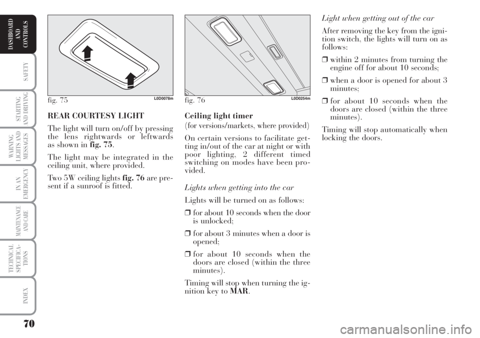
nition key to MAR. REAR COURTESY LIGHT
The light will turn on/off by pressing
the lens rightwards or leftwards
as shown in fig. 75.
The light may be integrated in the
ceiling unit, where provided.
Two 5W ceiling lights fig. 76are pre-
sent if a sunroof is fitted.
fig. 75L0D0078mfig. 76L0D0254m
Page 78 of 218
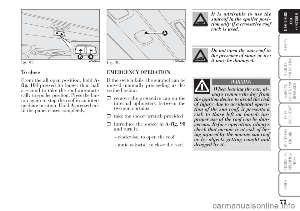
EMERGENCY OPERATION
If the switch fails, the sunroof can be
moved manually proceeding as de-
scribed below:
❒remove the protective cap on the
internal upholstery between the
two sun curtains.
❒take the socket wrench provided
❒introduce the socket in A-fig. 98
and turn it:
– clockwise, to open the roof
– anticlockwise, to close the roof. To close
From the all open position, hold A-
fig. 101pressed for longer than half
a second to take the roof automati-
cally to spoiler position. Press the but-
ton again to stop the roof in an inter-
mediate position. Hold Apressed un-
til the panel closes completely.
77
SAFETY
STARTING
AND DRIVING
WARNING
LIGHTS AND
MESSAGES
IN AN
EMERGENCY
MAINTENANCE
AND CARE
TECHNICAL
SPECIFICA-
TIONS
INDEX
DASHBOARD
AND
CONTROLS
fig. 97L0D0098mfig. 98L0D0099m
It is advisable to use the
sunroof in the spoiler posi-
tion only if a crosswise roof
rack is used.
Do not open the sun roof in
the presence of snow or ice:
it may be damaged.
When leaving the car, al-
ways remove the key from
the ignition device to avoid the risk
of injury due to accidental opera-
tion of the sun roof; it presents a
risk to those left on board: im-
proper use of the roof can be dan-
gerous. Before operation, always
check that no-one is at risk of be-
ing injured by the moving sun roof
or by objects getting caught and
dragged by it.
WARNING
Page 81 of 218
80
SAFETY
STARTING
AND DRIVING
WARNING
LIGHTS AND
MESSAGES
IN AN
EMERGENCY
MAINTENANCE
AND CARE
TECHNICAL
SPECIFICA-
TIONS
INDEX
DASHBOARD
AND
CONTROLS
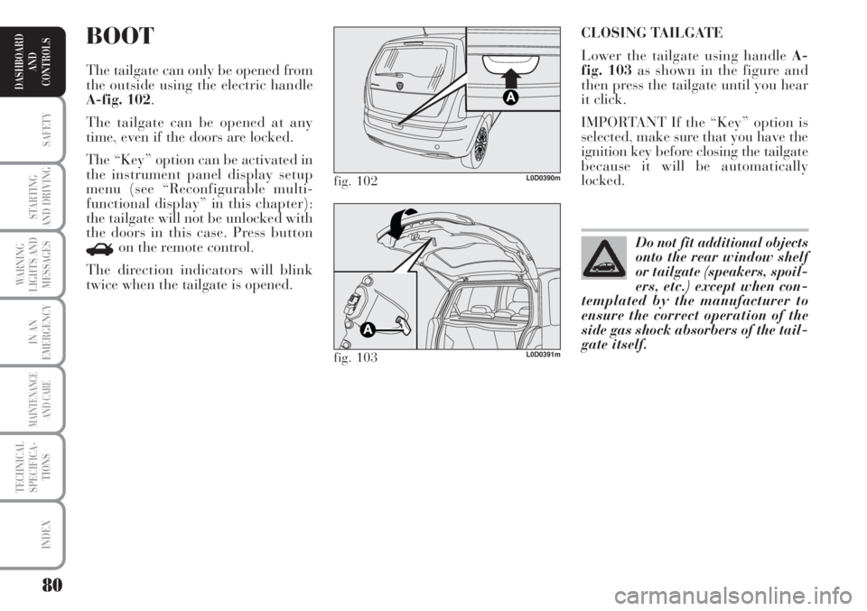
CLOSING TAILGATE
Lower the tailgate using handle A-
fig. 103as shown in the figure and
then press the tailgate until you hear
it click.
IMPORTANT If the “Key” option is
selected, make sure that you have the
ignition key before closing the tailgate
because it will be automatically
locked.BOOT
The tailgate can only be opened from
the outside using the electric handle
A-fig. 102.
The tailgate can be opened at any
time, even if the doors are locked.
The “Key” option can be activated in
the instrument panel display setup
menu (see “Reconfigurable multi-
functional display” in this chapter):
the tailgate will not be unlocked with
the doors in this case. Press button
Ron the remote control.
The direction indicators will blink
twice when the tailgate is opened.
fig. 102L0D0390m
fig. 103L0D0391m
Do not fit additional objects
onto the rear window shelf
or tailgate (speakers, spoil-
ers, etc.) except when con-
templated by the manufacturer to
ensure the correct operation of the
side gas shock absorbers of the tail-
gate itself.
Page 83 of 218
82
SAFETY
STARTING
AND DRIVING
WARNING
LIGHTS AND
MESSAGES
IN AN
EMERGENCY
MAINTENANCE
AND CARE
TECHNICAL
SPECIFICA-
TIONS
INDEX
DASHBOARD
AND
CONTROLS
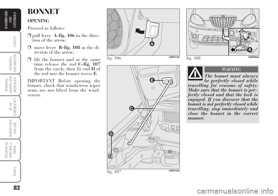
BONNET
OPENING
Proceed as follows:
❒pull lever A-fig. 106in the direc-
tion of the arrow;
❒move lever B-fig. 108 in the di-
rection of the arrow;
❒lift the bonnet and at the same
time release the rod C-fig. 107
from the catch, then fit end Dof
the rod into the bonnet recess E.
IMPORTANT Before opening the
bonnet, check that windscreen wiper
arms are not lifted from the wind-
screen.
fig. 106L0D0113m
fig. 107L0C0115m
fig. 108L0D0392m
The bonnet must always
be perfectly closed while
travelling for reasons of safety.
Make sure that the bonnet is per-
fectly closed and that the lock is
engaged. If you discover that the
bonnet is not perfectly closed while
travelling, stop immediately and
close the bonnet in the correct
manner.
WARNING
Page 86 of 218
85
SAFETY
STARTING
AND DRIVING
WARNING
LIGHTS AND
MESSAGES
IN AN
EMERGENCY
MAINTENANCE
AND CARE
TECHNICAL
SPECIFICA-
TIONS
INDEX
DASHBOARD
AND
CONTROLS
ABS SYSTEM
The car is fitted with an ABS braking
system, which prevents the wheels
from locking when braking, makes
the most of road grip and gives the
best control when emergency braking
under difficulty road conditions.
System is completed by EBD (Elec-
tronic Braking force Distribution),
which distributes the braking action
between front and rear wheels.
IMPORTANT The braking system
needs to settle for approximately 500
km: during this time, avoid sudden,
repeated and prolonged braking.SYSTEM INTERVENTION
Intervention of the ABS is detected by
a slight pulsing of the brake pedal ac-
companied by noise: such an event in-
dicates that you need to adjust your
speed to the type of road on which
you are travelling.
MECHANICAL BRAKE ASSIST
(emergency braking assistance)
(for versions/markets, where
provided)
This system (which cannot be deacti-
vated) recognises emergency braking
conditions according to the speed of
operation of the brake pedal and pro-
vides an additional hydraulic braking
pressure to support that provided by
the driver. This allows faster and
more powerful operation of the
braking system.
IMPORTANT When the Mechanical
Brake Assist is activated noises can be
heard from the system. This is nor-
mal. Anyway, while braking keep the
brake pedal depressed.
When the ABS intervenes
it means that you are ap-
proaching the grip limit between
tyres and road: slow down to ex-
ploit all the available grip.
WARNING
The ABS exploits the tyre-
road grip at the best, but it
cannot improve it; you should
therefore take every care when dri-
ving on slippery surfaces without
taking unnecessary risks.
WARNING
FAILURE INDICATIONS
ABS failure
ABS failure is indicated by the turn-
ing on of warning light >on the in-
strument panel together with the ded-
icated message on the multifunctional
display (for versions/markets, where
provided), (see section “Warning
lights and messages”).
In the case, the braking system will
work as normal without the extra po-
tentials offered by the ABS system.
Drive carefully to the nearest Lancia
Dealership to have the system
checked.
EBD failure
ABS failure is indicated by the
turning on warning lights >andx
on the instrument panel together with
a message on the multifunctional
display (for versions/markets, where
provided), (see section “Warning
lights and messages”).
Page 87 of 218
86
SAFETY
STARTING
AND DRIVING
WARNING
LIGHTS AND
MESSAGES
IN AN
EMERGENCY
MAINTENANCE
AND CARE
TECHNICAL
SPECIFICA-
TIONS
INDEX
DASHBOARD
AND
CONTROLS
EOBD SYSTEM
The EOBD system (European On
Board Diagnosis) allows continuous
diagnosis of the components of the car
correlated with emissions.
It also alerts the driver, by turning on
the warning light
Uon the instru-
ment panel (together with relevant
message on the multifunctional dis-
play, for versions/markets, where pro-
vided) (see section “Warning lights
and messages”), when these condi-
tions are no longer in peak conditions.
The objective is:
❒to keep the system efficiency under
control;
❒warn when a fault causes emissions
levels to increase;
❒to signal the need to replace deteri-
orated components. In this case, the rear wheels may sud-
denly lock and the car may swerve.
Drive carefully to the nearest Lancia
Dealership to have the system
checked.The system also has a diagnostic con-
nector that can be interfaced with ap-
propriate tools, which makes it possi-
ble to read the error codes stored in
the control unit, together with a series
of specific parameters for engine op-
eration and diagnosis. This check can
also be carried out by the traffic po-
lice.
IMPORTANT After eliminating the
inconvenience, to check the system
completely, Lancia Dealerships are
obliged to run a bench test and, if
necessary, road tests which may also
call for a long journey.
When the ABS cuts in, and
you feel the brake pedal
pulsating, do not remove your foot,
but keep it pressed; in doing so you
will stop in the shortest amount of
space possible under the current
road conditions.
WARNING
If warning light xonly
lights up on the instrument
panel (with a message on the mul-
tifunctional display, for ver-
sions/markets, where provided),
stop the car immediately and go to
the nearest Lancia Dealership.
Leakage of hydraulic fluid from
the braking system will compro-
mise functionality of the braking
system, either of the conventional
type or with ABS.
WARNING
Go to a Lancia Dealership
as soon as possible if warn-
ing light Ueither does not
light up when the key is
turned to MAR to if while travelling
the warning lights comes on either
steady or blinking (along with a
message on the multifunctional dis-
play, where provided). The opera-
tion of warning light Umay be
checked by the traffic police using
specific devices. Follow the laws in
force in the country where you are
driving.
Page 91 of 218
90
SAFETY
STARTING
AND DRIVING
WARNING
LIGHTS AND
MESSAGES
IN AN
EMERGENCY
MAINTENANCE
AND CARE
TECHNICAL
SPECIFICA-
TIONS
INDEX
DASHBOARD
AND
CONTROLS
The car can be driven using the me-
chanical steering in case of failure to
the electric power steering system.
Take the car to a Lancia Dealership
as soon as possible.
IMPORTANT The steering may be-
fore stiffer when parking requiring a
lot of steering. This is normal and
caused by the electric control motor
overheating system. No repairs are
needed. The power steering system
will start working properly again the
next time the car is used. PARKING SENSORS
(for versions/markets, where provided)
Parking sensors are located in the rear
bumper and their function is to in-
form the driver, through an intermit-
tent buzzer, about the presence of ob-
stacles behind the car.
ACTIVATION
The sensors are automatically acti-
vated when the reverse gear is en-
gaged. As the distance from the ob-
stacle behind the car decreases, the
acoustic alarm becomes more fre-
quent.
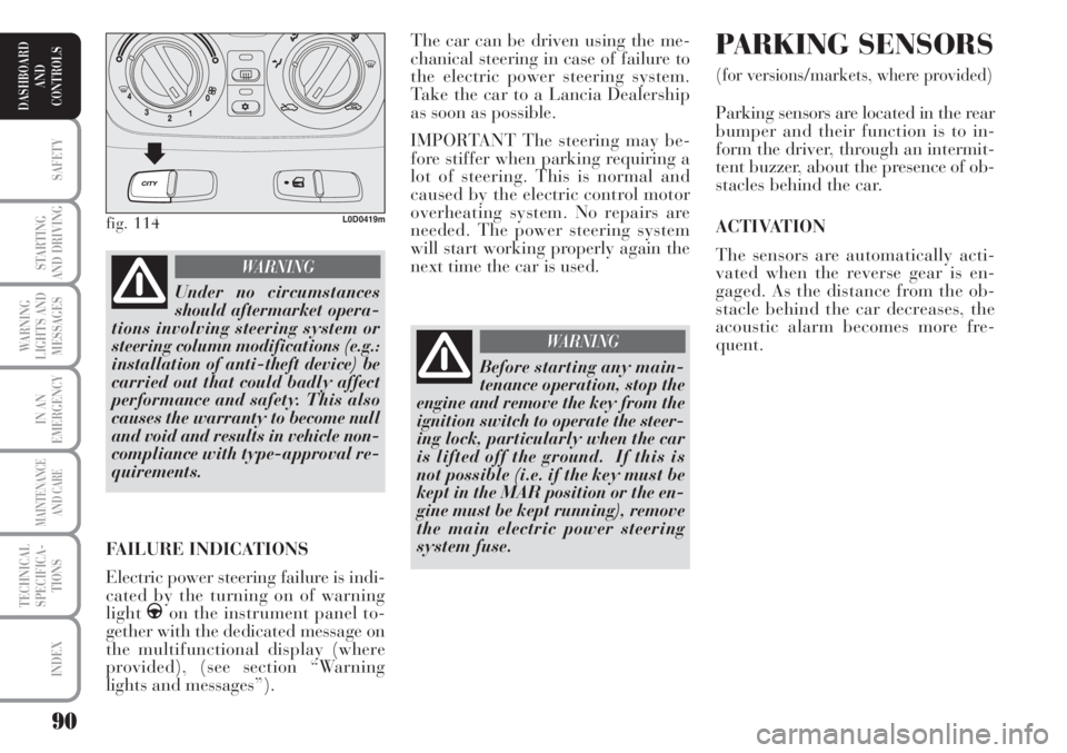
fig. 114L0D0419m
Under no circumstances
should aftermarket opera-
tions involving steering system or
steering column modifications (e.g.:
installation of anti-theft device) be
carried out that could badly affect
performance and safety. This also
causes the warranty to become null
and void and results in vehicle non-
compliance with type-approval re-
quirements.
WARNING
FAILURE INDICATIONS
Electric power steering failure is indi-
cated by the turning on of warning
light
gon the instrument panel to-
gether with the dedicated message on
the multifunctional display (where
provided), (see section “Warning
lights and messages”).
Before starting any main-
tenance operation, stop the
engine and remove the key from the
ignition switch to operate the steer-
ing lock, particularly when the car
is lifted off the ground. If this is
not possible (i.e. if the key must be
kept in the MAR position or the en-
gine must be kept running), remove
the main electric power steering
system fuse.
WARNING