lock Lancia Thema 2013 Owner handbook (in English)
[x] Cancel search | Manufacturer: LANCIA, Model Year: 2013, Model line: Thema, Model: Lancia Thema 2013Pages: 336, PDF Size: 3.87 MB
Page 39 of 336

WARNING!
The belt and retractor assembly
must be replaced if the seat belt
assembly Automatic Locking Re-
tractor (ALR) feature or any other
seat belt function is not working
properly when checked according
to the procedures in the Service
Manual. Failure to replace the belt andretractor assembly could increase
the risk of injury in collisions.
SEAT BELT
PRETENSIONERS
The seat belts for both front seating
positions are equipped with preten-
sioning devices that are designed to
remove slack from the seat belt in the
event of a collision. These devices may
improve the performance of the seat
belt by assuring that the belt is tight
about the occupant early in a colli-
sion. Pretensioners work for all size
occupants, including those in child
restraints. NOTE:
These devices are not a
substitute for proper seat belt place-
ment by the occupant. The seat belt
still must be worn snugly and posi-
tioned properly.
The pretensioners are triggered by the
Occupant Restraint Controller (ORC).
Like the air bags, the pretensioners are
single use items. A deployed preten-
sioner or a deployed air bag must be
replaced immediately.ACTIVE HOOD SYSTEM
(for versions/markets,
where provided)
The Active Hood system is intended to
enhance pedestrian protection by ele-
vating the vehicle’s hood upon an im-
pact with a pedestrian or other object.
The system is automatically activated
when the vehicle is moving within a
specified vehicle speed range. In order
to detect a range of pedestrians, other
objects that are impacted may result
in an Active Hood deployment. Deployment Sensors And Controls
The Occupant Restraint Controller
(ORC) determines if deployment of
the actuators in a frontal impact is
required. Based on the impact sensors
signals, the ORC determines when to
deploy the actuators. The impact
sensors are located within the front
bumper area.
The ORC monitors the readiness of
the electronic parts of the Active Hood
system whenever the ignition switch is
in the START or ON/RUN position.
If the key is in the LOCK position, in
the ACC position, or not in the igni-
tion, the Active Hood system is not on
and the Active Hood will not deploy.
The ORC contains a backup power
supply system that may deploy the
actuators even if the battery loses
power or it becomes disconnected
prior to deployment.
33
Page 45 of 336

NOTE:
Air Bag covers may not be obvious
in the interior trim, but they will
open during air bag deployment. Being too close to the side airbags during deployment could
cause you to be severely injured
or killed.
SAB and SABIC air bags are a supple-
ment to the seat belt restraint system.
Occupants, including children who
are up against or very close to SAB or
SABIC air bags can be seriously in-
jured or killed. Occupants, especially
children, should not lean on or sleep
against the door, side windows, or
area where the SAB or SABIC air bags
inflate, even if they are in an infant or
child restraint. Always sit upright as
possible with your back against the
seat back, use the seat belts properly,
and use the appropriate sized child
restraint, infant restraint or booster
seat recommended for the size and
weight of the child. The system includes side impact sen-
sors that are calibrated to deploy the
side air bags during impacts that re-
quire air bag occupant protection.
WARNING!
Your vehicle is equipped with
SABIC air bags, do not have any
accessory items installed which
will alter the roof, including add-
ing a sunroof to your vehicle. Do
not add roof racks that require
permanent attachments (bolts or
screws) for installation on the ve-
hicle roof. Do not drill into the
roof of the vehicle for any reason.
Your vehicle is equipped with left
and right Supplemental Side Air
Bag Inflatable Curtain (SABIC),
do not stack luggage or other cargo
up high enough to block the loca-
tion of the SABIC. The area where
the SABIC is located should re-
main free from any obstructions.
(Continued)
WARNING! (Continued)
Do not use accessory seat covers or
place objects between you and the
side air bags; the performance
could be adversely affected and/or
objects could be pushed into you,
causing serious injury.
Supplemental Driver Side Knee
Air Bag
The Supplemental Driver Side Knee
Air Bag provides enhanced protection
and works together with the Driver
Advanced Front Air Bag during a
frontal impact.
Knee Impact Bolsters
The Knee Impact Bolsters help pro-
tect the knees of the driver and the
front passenger, and position front oc-
cupants for the best interaction with
the Advanced Front Air Bags.
Along with seat belts and pretension-
ers, Advanced Front Air Bags work
with the knee bolsters to provide im-
proved protection for the driver and
39
Page 49 of 336
The SAB fully inflate in about 10 milli-
seconds. The side air bag moves at a
very high speed and with such a high
force that it could injure you if you are
not seated properly, or if items are
positioned in the area where the side
air bag inflates. This especially ap-
plies to children.
Supplemental Side Air Bag
Inflatable Curtain (SABIC)
Inflator Units
During collisions where the impact is
confined to a particular area of the
side of the vehicle, the ORC may de-
ploy the SABIC air bags, depending
on the severity and type of collision.
In these events, the ORC will deploy
the SABIC only on the impact side of
the vehicle.
A quantity of non-toxic gas is gener-
ated to inflate the side curtain air bag.
The inflating side curtain air bag
pushes the outside edge of the head-
liner out of the way and covers the
window. The air bag inflates in about
30 milliseconds (about one-quarter of
the time that it takes to blink your
eyes) with enough force to injure youif you are not belted and seated prop-
erly, or if items are positioned in the
area where the side curtain air bag
inflates. This especially applies to
children. The side curtain air bag is
only about 9 cm thick when it is in-
flated.
Because air bag sensors estimate de-
celeration over time, vehicle speed
and damage are not good indicators of
whether or not an air bag should have
deployed.
NOTE: In a rollover the preten-
sioners and/or SAB and SABIC air
bags may deploy on both sides of
the vehicle.
Front And Side Impact Sensors
In front and side impacts, impact sen-
sors can aid the ORC in determining
appropriate response to impact events.Enhanced Accident Response
System
In the event of an impact causing air
bag deployment, if the communica-
tion network remains intact, and the
power remains intact, depending on
the nature of the event the ORC willdetermine whether to have the En-
hanced Accident Response System
perform the following functions:
Cut off fuel to the engine.
Flash hazard lights as long as the
battery has power or until the igni-
tion is cycled off.
Turn on the interior lights, which
remain on as long as the battery has
power or until the ignition key is
removed. Unlock the doors automatically.
In order to reset the Enhanced Acci-
dent Response System functions after
an event, the ignition switch must be
changed from IGN ON to IGN OFF.
If A Deployment Occurs
The Advanced Front Air Bags are
designed to deflate immediately after
deployment.
NOTE:
Front and/or side air bags
will not deploy in all collisions.
This does not mean something is
wrong with the air bag system.
43
Page 51 of 336
WARNING!(Continued)
Do not attempt to modify any part
of your air bag system. The air bag
may inflate accidentally or may
not function properly if modifica-
tions are made. Take your vehicle
to an authorized dealer for any
air bag system service. If your seat,
including your trim cover and
cushion, needs to be serviced in
any way (including removal or
loosening/tightening of seat at-
tachment bolts), take the vehicle
to your authorized dealer. Only
manufacturer approved seat ac-
cessories may be used. If it is nec-
essary to modify the air bag system
for persons with disabilities, con-
tact your authorized dealer.
Air Bag Warning Light
You will want to have the
air bags ready to inflate for
your protection in a colli-
sion. The Air Bag Warning
Light monitors the internal circuits
and interconnecting wiring associated with air bag system electrical compo-
nents. While the air bag system is
designed to be maintenance free. If
any of the following occurs, have an
authorized dealer service the air bag
system immediately.
The Air Bag Warning Light does
not come on during the four to eight
seconds when the ignition is first
cycled to the ON/RUN.
The Air Bag Warning Light remains on after the four to eight-second
interval.
The Air Bag Warning Light comes on intermittently or remains on
while driving.
NOTE:
If the speedometer, ta-
chometer, or any engine related
gauges are not working, the Occu-
pant Restraint Controller (ORC)
may also be disabled. The air bags
may not be ready to inflate for your
protection. Promptly check the fuse
block for blown fuses. Refer to the
label located on the inside of the
fuse block cover for the proper air
bag fuses. See your authorized
dealer if the fuse is good.
Event Data Recorder (EDR)This vehicle is equipped with an event
data recorder (EDR). The main pur-
pose of an EDR is to record, in certain
crash or near crash-like situations,
such as an air bag deployment or hit-
ting a road obstacle, data that will
assist in understanding how a vehicle’s
systems performed. The EDR is de-
signed to record data related to vehicle
dynamics and safety systems for a
short period of time, typically 30 sec-
onds or less. The EDR in this vehicle is
designed to record such data as: How various systems in your ve-
hicle were operating;
Whether or not the driver and pas- senger safety belts were
buckled/fastened;
How far (if at all) the driver was depressing the accelerator and/or
brake pedal; and,
How fast the vehicle was traveling.
These data can help provide a better
understanding of the circumstances in
which crashes and injuries occur.
45
Page 59 of 336
WARNING!
An incorrectly anchored tether
strap could lead to increased head
motion and possible injury to the
child. Use only the anchor positions
directly behind the child seat to se-
cure a child restraint top tether
strap.
NOTE:
Ensure that the tether strap does
not slip into the opening between
the seatbacks as you remove
slack in the strap.
When using the ISOFIX attaching
system to install a child restraint,
please ensure that all seat belts
not being used for occupant re-
straints are stowed and out of
reach of children. It is recom-
mended that before installing the
child restraint, buckle the seat
belt so the seat belt is tucked be-
hind the child restraint and out
of reach. If the buckled seat belt
interferes with the child restraint
installation, instead of tucking
the seat belt behind the child
restraint, route the seat belt
through the child restraint belt
path and then buckle it. This
should stow the seat belt out of
the reach of an inquisitive child.
Remind all children in the ve-
hicle that the seat belts are not
toys and should not be played
with, and never leave your child
unattended in the vehicle.
WARNING!
Improper installation of a child
restraint to the ISOFIX anchorages
can lead to failure of an infant or
child restraint. The child could be
badly injured or killed. Follow the
manufacturer's directions exactly
when installing an infant or child
restraint.
Installing Child Restraints Using
The Vehicle Seat Belt
The seat belts in the rear passenger
seating positions are equipped with
an Automatic Locking Retractor
(ALR) to secure a Child Restraint
System (CRS). These types of seat
belts are designed to keep the lap
portion of the seat belt tight around
the child restraint so that it is not
necessary to use a locking clip. The
ALR will make a ratcheting noise if
you extract the entire belt from the
retractor and then allow the belt to
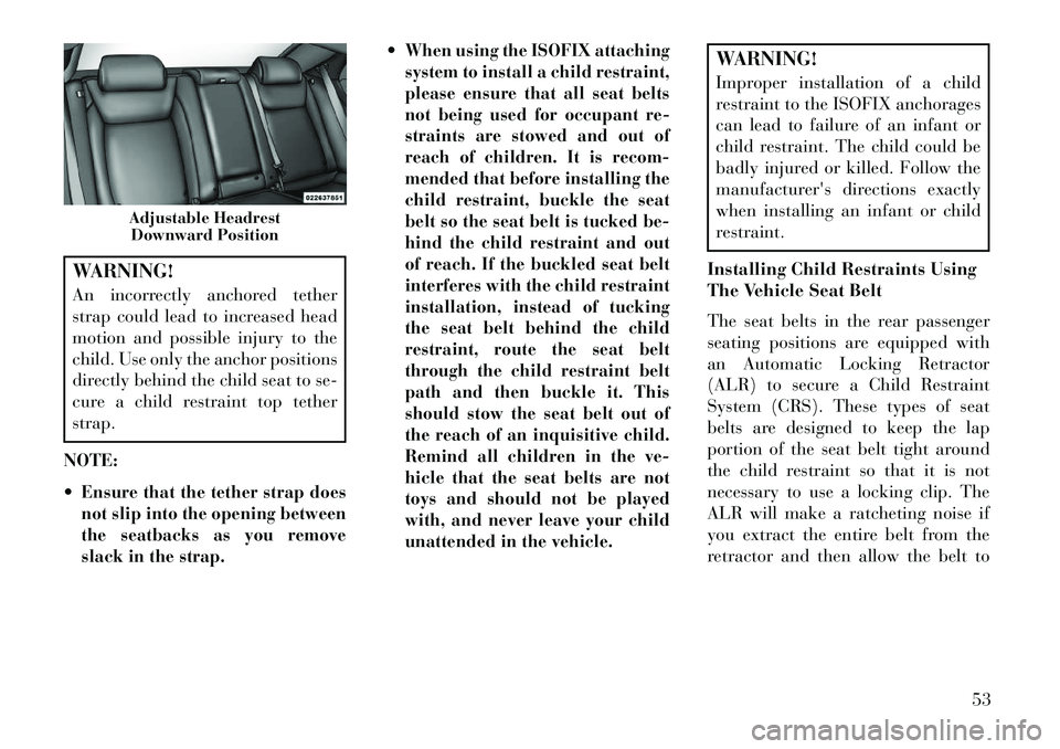
Adjustable Headrest Downward Position
53
Page 60 of 336

retract into the retractor. For addi-
tional information on ALR, refer to
“Automatic Locking Mode”. The
chart below defines the seating posi-
tions with an Automatic Locking Re-
tractor (ALR) or a cinching latch
plate.
Driver Center Passen-ger
First
Row N/A N/A N/A
Second
Row ALR ALR ALR
N/A — Not ApplicableALR — Automatic Locking RetractorInstalling a Child Restraint with an
ALR:
1. To install a child restraint with
ALR, first, pull enough of the seat belt
webbing from the retractor to route it
through the belt path of the child re-
straint. Slide the latch plate into the
buckle until you hear a “click.” Next,
extract all the seat belt webbing out of
the retractor and then allow the belt to
retract into the retractor. As the belt retracts, you will hear a ratcheting
sound. This indicates the safety belt is
now in the Automatic Locking mode.
2. Finally, pull on any excess web-
bing to tighten the lap portion around
the child restraint. Any seat belt sys-
tem will loosen with time, so check the
belt occasionally, and pull it tight if
necessary.
In the rear center seat, you may
have trouble tightening the lap/
shoulder belt on the child restraint
because the buckle or latch plate is
too close to the belt path opening on
the restraint. Disconnect the latch
plate from the buckle and twist the
short buckle-end belt several times
to shorten it. Insert the latch plate
into the buckle with the release but-
ton facing out.
If the belt still can’t be tightened, or
if pulling and pushing on the re-
straint loosens the belt, disconnect
the latch plate from the buckle, turn
the buckle around, and insert the
latch plate into the buckle again.
If you still can’t make the child re-
straint secure, try a different seating
position.
To attach a child restraint tether strap:1. Rotate the cover over the anchor
directly behind the seat where you are
placing the child restraint.
2. Route the tether strap to provide
the most direct path for the strap be-
tween the anchor and the child seat.
3. Attach the tether strap hook (A) of
the child restraint to the anchor (B)
and remove slack in the tether strap
according to the child restraint manu-
facturer's instructions.
Tether Strap Mounting
1 — Cover A — Tether Strap
Hook
3 — Attaching
Strap B — Tether Anchor
54
Page 64 of 336
WARNING!(Continued)
If required, mounting posts must be
properly installed, if not equipped
from the factory.Failure to properly follow floor mat
installation or mounting can cause
interference with the brake pedal
and accelerator pedal operation
causing loss of control of the vehicle.Periodic Safety Checks You
Should Make Outside The
Vehicle
TiresExamine tires for excessive tread wear
and uneven wear patterns. Check for
stones, nails, glass, or other objects
lodged in the tread or sidewall. Inspect
the tread for cuts and cracks. Inspect
sidewalls for cuts, cracks and bulges.
Check the wheel nuts for tightness.
Check the tires (including spare) for
proper cold inflation pressure.
Lights
Have someone observe the operation
of brake lights and exterior lights
while you work the controls. Check
turn signal and high beam indicator
lights on the instrument panel.
Door Latches
Check for positive closing, latching,
and locking.
Fluid Leaks
Check area under vehicle after over-
night parking for fuel, engine coolant,
oil, or other fluid leaks. Also, if gaso-
line fumes are detected or if fuel,
power steering fluid (2500/3500), or
brake fluid leaks are suspected, the
cause should be located and corrected
immediately.
58
Page 76 of 336
BLIND SPOT
MONITORING
(for versions/markets,
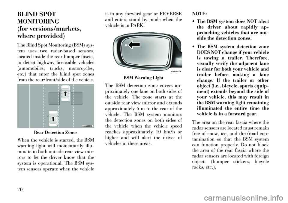
where provided)The Blind Spot Monitoring (BSM) sys-
tem uses two radar-based sensors,
located inside the rear bumper fascia,
to detect highway licensable vehicles
(automobiles, trucks, motorcycles,
etc.) that enter the blind spot zones
from the rear/front/side of the vehicle.When the vehicle is started, the BSM
warning light will momentarily illu-
minate in both outside rear view mir-
rors to let the driver know that the
system is operational. The BSM sys-
tem sensors operate when the vehicleis in any forward gear or REVERSE
and enters stand by mode when the
vehicle is in PARK.
The BSM detection zone covers ap-
proximately one lane on both sides of
the vehicle. The zone starts at the
outside rear view mirror and extends
approximately 6 m to the rear of the
vehicle. The BSM system monitors
the detection zones on both sides of
the vehicle when the vehicle speed
reaches approximately 10 km/h or
higher and will alert the driver of
vehicles in these areas.
NOTE:
The BSM system does NOT alert
the driver about rapidly ap-
proaching vehicles that are out-
side the detection zones.
The BSM system detection zone
DOES NOT change if your vehicle
is towing a trailer. Therefore,
visually verify the adjacent lane
is clear for both your vehicle and
trailer before making a lane
change. If the trailer or other
object (i.e., bicycle, sports equip-
ment) extends beyond the side of
your vehicle, this may result in
the BSM warning light remaining
illuminated the entire time the
vehicle is in a forward gear.The area on the rear fascia where the
radar sensors are located must remain
free of snow, ice, and dirt/road con-
tamination so that the BSM system
can function properly. Do not block
the area of the rear fascia where the
radar sensors are located with foreign
objects (bumper stickers, bicycle
racks, etc.).
Rear Detection Zones
BSM Warning Light
70
Page 78 of 336
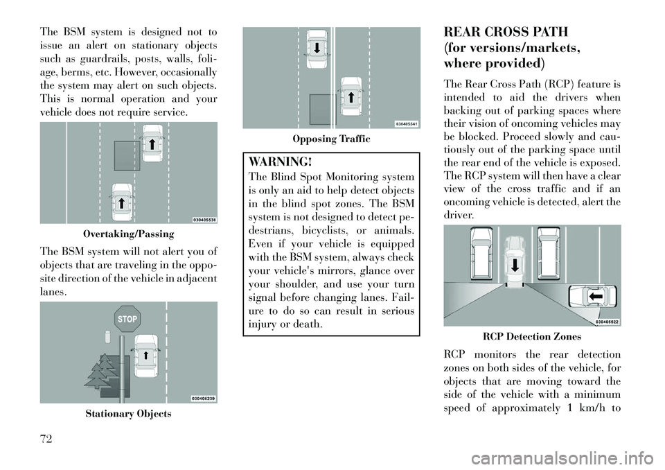
The BSM system is designed not to
issue an alert on stationary objects
such as guardrails, posts, walls, foli-
age, berms, etc. However, occasionally
the system may alert on such objects.
This is normal operation and your
vehicle does not require service.The BSM system will not alert you of
objects that are traveling in the oppo-
site direction of the vehicle in adjacent
lanes.
WARNING!
The Blind Spot Monitoring system
is only an aid to help detect objects
in the blind spot zones. The BSM
system is not designed to detect pe-
destrians, bicyclists, or animals.
Even if your vehicle is equipped
with the BSM system, always check
your vehicle's mirrors, glance over
your shoulder, and use your turn
signal before changing lanes. Fail-
ure to do so can result in serious
injury or death.REAR CROSS PATH
(for versions/markets,
where provided)
The Rear Cross Path (RCP) feature is
intended to aid the drivers when
backing out of parking spaces where
their vision of oncoming vehicles may
be blocked. Proceed slowly and cau-
tiously out of the parking space until
the rear end of the vehicle is exposed.
The RCP system will then have a clear
view of the cross traffic and if an
oncoming vehicle is detected, alert the
driver.
RCP monitors the rear detection
zones on both sides of the vehicle, for
objects that are moving toward the
side of the vehicle with a minimum
speed of approximately 1 km/h to
Overtaking/PassingStationary Objects
Opposing Traffic
RCP Detection Zones
72
Page 79 of 336

3 km/h, to objects moving a maxi-
mum of approximately 16 km/h, such
as in parking lot situations.
NOTE:
In a parking lot situation,
oncoming vehicles can be obscured
by vehicles parked on either side.
If the sensors are blocked by other
structures or vehicles, the system
will not be able to alert the driver.
When RCP is on and the vehicle is in
REVERSE, the driver is alerted using
both the visual and audible alarms,
including reducing the radio volume.WARNING!RCP is not a Back Up Aid system.
It is intended to be used to help a
driver detect an oncoming vehicle in
a parking lot situation. Drivers must
be careful when backing up, even
when using RCP. Always check care-
fully behind your vehicle, look be-
hind you, and be sure to check for
pedestrians, animals, other vehicles,
obstructions, and blind spots before
backing up. Failure to do so can
result in serious injury or death.
MODES OF OPERATION
Three selectable modes of operation
are available in the Uconnect Touch™
System. Refer to “Uconnect Touch™
Settings” in “Understanding Your
Instrument Panel” for further infor-
mation.
Blind Spot Alert
When operating in Blind Spot Alert
mode, the BSM system will provide a
visual alert in the appropriate side
view mirror based on a detected ob-
ject. However, when the system is op-
erating in RCP, the system will re-
spond with both visual and audible
alerts when a detected object is pres-
ent. Whenever an audible alert is re-
quested, the radio volume is reduced.
Blind Spot Alert Lights/Chime
When operating in Blind Spot Alert
Lights/Chime mode, the BSM system
will provide a visual alert in the ap-
propriate side view mirror based on a
detected object. If the turn signal is
then activated, and it corresponds to an alert present on that side of the
vehicle, an audible chime will also be
sounded. Whenever a turn signal and
detected object are present on the
same side at the same time, both the
visual and audio alerts will be issued.
In addition to the audible alert, the
radio (if on) volume will be reduced.
NOTE:
Whenever an audible alert is
requested by the BSM system,
the radio volume is reduced.
If the hazard flashers are on, the system will request the ap-
propriate visual alert only.
When the system is in RCP, the system
shall respond with both visual and
audible alerts when a detected object
is present. Whenever an audible alert
is requested, the radio is also muted.
Turn/hazard signal status is ignored;
the RCP state always requests the
audible chime.
73