boot Lancia Thesis 2006 Owner handbook (in English)
[x] Cancel search | Manufacturer: LANCIA, Model Year: 2006, Model line: Thesis, Model: Lancia Thesis 2006Pages: 386, PDF Size: 8.69 MB
Page 276 of 386
275
CHANGING
A WHEEL
Please note:
– the jack weighs 2.100 kg;
– the jack requires no adjustments;
– the jack cannot be repaired. If it
breaks, it must be replaced with a
genuine spare part;
– no other tool, part from the
ratchet wrench, can be fitted to the
jack.Change the wheel as follows:
1) Stop the car so that it is not a
hazard for other road users or your-
self when changing the wheel. The
ground should be as flat and firm as
possible.
2) Turn engine off and engage the
electric parking brake.
3) Engage first gear or reverse. On
versions with automatic gearbox
shift the lever to P.4) Open the boot.
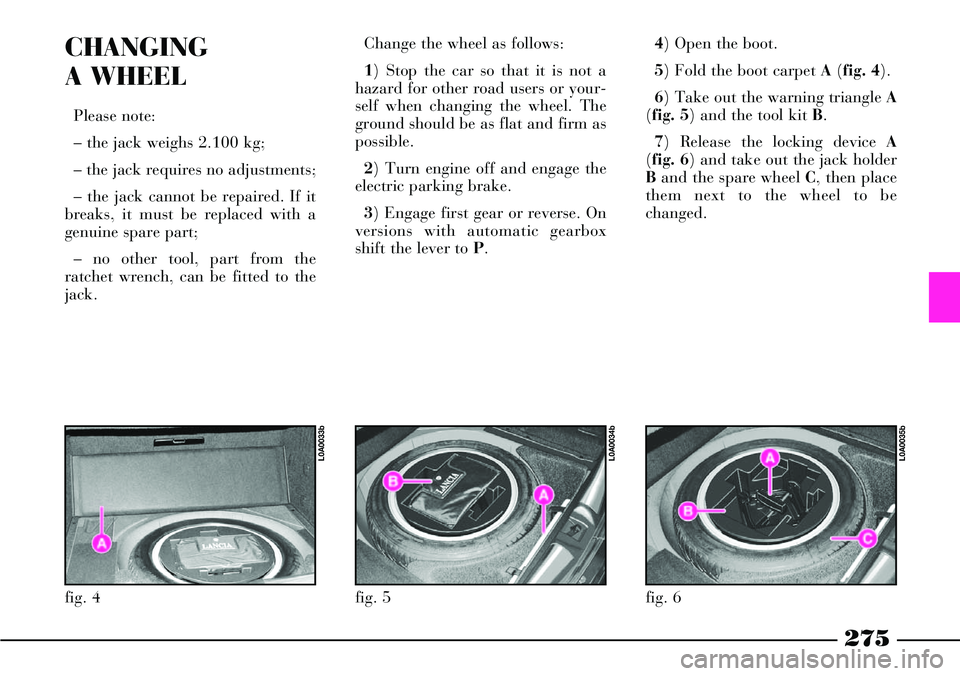
5) Fold the boot carpet A(fig. 4).
6) Take out the warning triangle A
(fig. 5) and the tool kit B.
7) Release the locking device A
(fig. 6) and take out the jack holder
Band the spare wheel C, then place
them next to the wheel to be
changed.
fig. 4
L0A0033b
fig. 5
L0A0034b
fig. 6
L0A0035b
Page 281 of 386

280
Bolt tightening torque
must be 98 Nm (10 kgm).
After replacing the
wheel, you are advised to have
the wheel bolt tightening checked
at a Lancia Dealership as soon as
possible.
Insufficient tightening could
actually make the wheel bolts
loosen too much, with clearly
dangerous consequences. If the
bolts are tightened too much, they
could be damaged and their
resistance might be compro-
mised.23) Place the removed wheel, the
jack and the tools in the boot and
fasten appropriately.
IMPORTANTPut the jack back
into B(fig. 8) and clamp it by
screwing handle A(fig. 8) manually
in order to prevent vibrations during
travelling.
fig. 19
L0A0045b
fig. 20
L0A0365b
fig. 21
L0A0368b
21) Tighten up the wheel bolts in a
criss-cross fashion, following the
sequence shown:
- fig. 19= versions with alloy rims
- fig. 20= versions with steel rims.
22) On versions with alloy rims,
refit the wheel hub cap pressing it
slightly. On versions with steel rims,
approach the wheel cap making the
inflating valve A(fig. 21) coincide
with flaring B. Press the cap circum-
ference starting near the inflating
valve and proceeding until fitting
the cap completely.
IMPORTANTThe wheel hub cap
(alloy rims) or the wheel cap (steel
rims) may fly off when the car is
moving if it is not fastened correctly.
Page 284 of 386
283
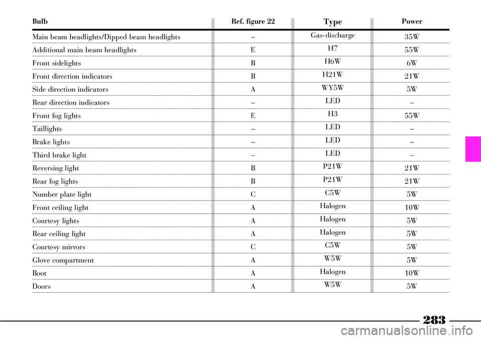
Bulb
Main beam headlights/Dipped beam headlights
Additional main beam headlights
Front sidelights
Front direction indicators
Side direction indicators
Rear direction indicators
Front fog lights
Taillights
Brake lights
Third brake light
Reversing light
Rear fog lights
Number plate light
Front ceiling light
Courtesy lights
Rear ceiling light
Courtesy mirrors
Glove compartment
Boot
Doors
Power
35W
55W
6W
21W
5W
–
55W
–
–
–
21W
21W
5W
10W
5W
5W
5W
5W
10W
5W
Type
Gas-discharge
H7
H6W
H21W
WY5W
LED
H3
LED
LED
LED
P21W
P21W
C5W
Halogen
Halogen
Halogen
C5W
W5W
Halogen
W5W
Ref. figure 22
–
E
B
B
A
–
E
–
–
–
B
B
C
A
A
A
C
A
A
A
Page 291 of 386

290
COURTESY MIRROR LIGHTS
To replace the courtesy mirror
bulbs:
1) Lift the mirror cover A(fig. 38).
2) Remove the mirror by levering
in B.
IMPORTANTBe very careful
when removing the mirror to avoid
damaging its frame and the mirror
itself.3) Remove the bulbs C(fig. 39)
releasing them from the side con-
tacts and replace them.
4) Refit the mirror inserting first
the upper edge and then pressing the
lower edge until it fits.BOOT LIGHT
To replace the bulb:
1) Remove the lens by using a
screwdriver as a lever on clip A
(fig. 40).
2) Press the two sides of shield B
(fig. 41) at the fastening clips and
remove it.
fig. 38
L0A0136b
fig. 39
L0A0137b
fig. 40
L0A0139b
Page 294 of 386
293
FUSE LOCATION
The main fuses of THESIS are con-
tained into four fuse boxes, to be
found on the left side of the dash-
board, in the engine compartment,
on the battery and in the right side
compartment of the boot.
GENERAL FUSES
(MIDI-FUSE and MEGA-FUSE)
The car is fitted with a set of gen-
eral fuses (MIDI-FUSE and MEGA-
FUSE) which separately protect the
various electrical system functions in
addition to the individual device
fuses.
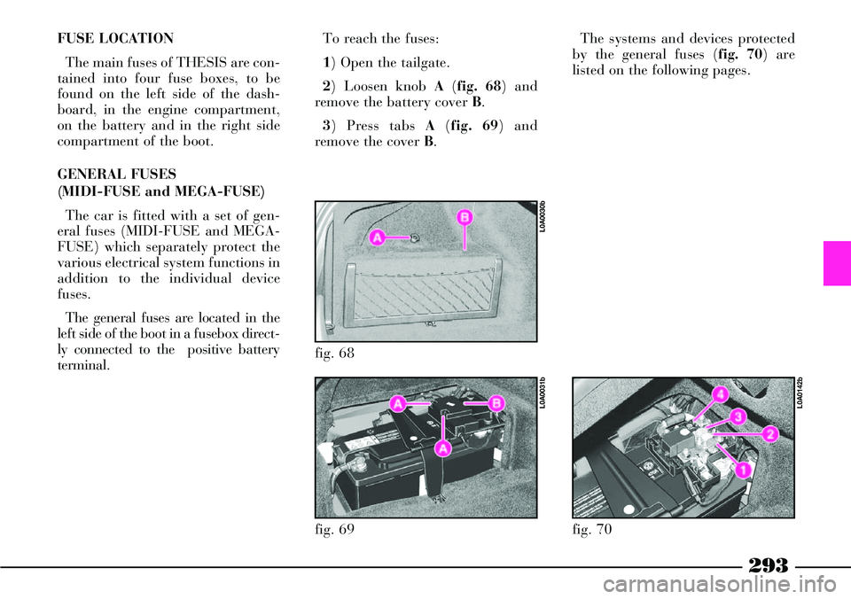
The general fuses are located in the
left side of the boot in a fusebox direct-
ly connected to the positive battery
terminal.To reach the fuses:
1) Open the tailgate.
2) Loosen knob A(fig. 68) and
remove the battery cover B.
3) Press tabs A(fig. 69) and
remove the cover B.The systems and devices protected
by the general fuses (fig. 70) are
listed on the following pages.
fig. 68
L0A0030b
fig. 69
L0A0031b
fig. 70
L0A0142b
Page 296 of 386

295
The devices protected by the fuses
(fig. 75) are listed in the tables on
the following pages.
After replacing the fuses refit the
cover by refitting the fastening clips.FUSES IN THE BOOT
The fusebox (fig. 77) is located on
the right side of the boot, inside the
service compartment.
To open the compartment flap turn
the catch A(fig. 76) to 1with the
ignition key and lower it. The spare fuses, with different
amperage, are housed in vertical
position at the sides of the fusebox.
The devices protected by the fuses
(fig. 78) are listed in the tables on
the following pages.
fig. 75
L0A0267b
fig. 76
L0A0275b
fig. 77
L0A0146b
fig. 78
L0A0266b
Page 297 of 386
296
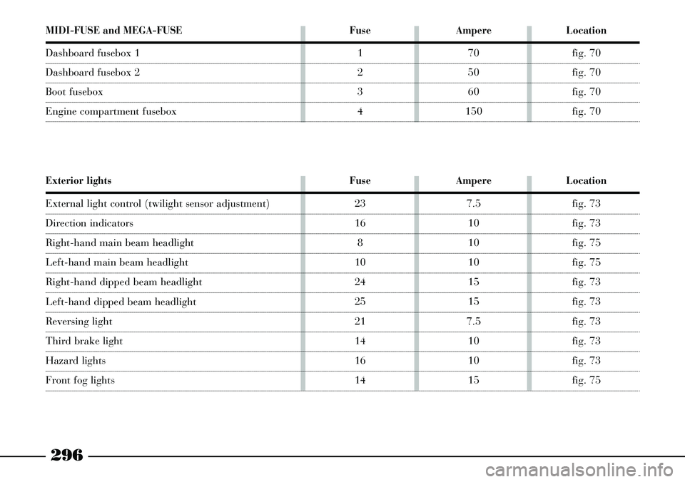
MIDI-FUSE and MEGA-FUSE
Dashboard fusebox 1
Dashboard fusebox 2
Boot fusebox
Engine compartment fusebox
Fuse
1
2
3
4
Ampere
70
50
60
150
Location
fig. 70
fig. 70
fig. 70
fig. 70
Exterior lights
External light control (twilight sensor adjustment)
Direction indicators
Right-hand main beam headlight
Left-hand main beam headlight
Right-hand dipped beam headlight
Left-hand dipped beam headlight
Reversing light
Third brake light
Hazard lights
Front fog lights
Fuse
23
16
8
10
24
25
21
14
16
14
Ampere
7.5
10
10
10
15
15
7.5
10
10
15
Location
fig. 73
fig. 73
fig. 75
fig. 75
fig. 73
fig. 73
fig. 73
fig. 73
fig. 73
fig. 75
Page 298 of 386
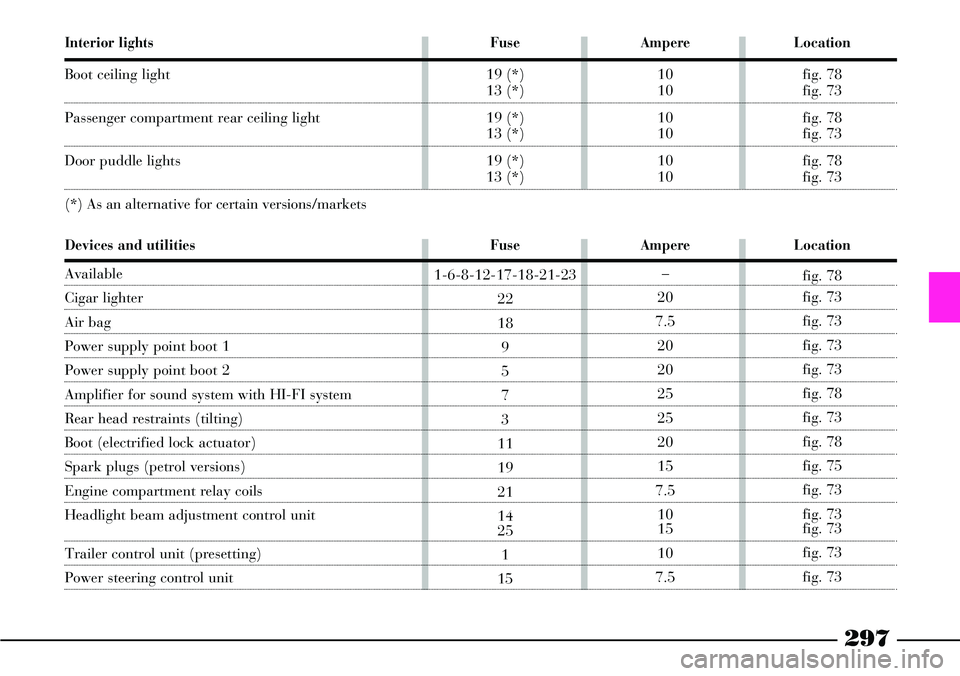
297
Interior lights
Boot ceiling light
Passenger compartment rear ceiling light
Door puddle lights
(*) As an alternative for certain versions/markets
Fuse
19 (*)
13 (*)
19 (*)
13 (*)
19 (*)
13 (*)
Ampere
10
10
10
10
10
10
Location
fig. 78
fig. 73
fig. 78
fig. 73
fig. 78
fig. 73
Fuse
1-6-8-12-17-18-21-23
22
18
9
5
7
3
11
19
21
14
25
1
15
Ampere
–
20
7.5
20
20
25
25
20
15
7.5
10
15
10
7.5
Location
fig. 78
fig. 73
fig. 73
fig. 73
fig. 73
fig. 78
fig. 73
fig. 78
fig. 75
fig. 73
fig. 73
fig. 73
fig. 73
fig. 73
Devices and utilities
Available
Cigar lighter
Air bag
Power supply point boot 1
Power supply point boot 2
Amplifier for sound system with HI-FI system
Rear head restraints (tilting)
Boot (electrified lock actuator)
Spark plugs (petrol versions)
Engine compartment relay coils
Headlight beam adjustment control unit
Trailer control unit (presetting)
Power steering control unit
Page 301 of 386

300
Devices and utilities
Passenger door point (power supply)
Instrument panel point
Steering angle sensor point
(*) As an alternative for certain versions/markets
Parking sensor point
TV tuner point
Boot point
Steering wheel point
Central console control panels
Fuel pump
Doors (electrified lock actuators)
Spark plug pre-heating
EOBD system diagnostic socket
Current socket in boot
Current socket in rear armrest
Parking heater (control unit)
Additional heater
Fuse
10
14
16
19 (*)
13 (*)
19
15
14
15
11
15
15
21
11
2
6
22
13
2
3
4
9
Ampere
20
10
10
10
10
7.5
7.5
10
7.5
20
7.5
7.5
15
20
60
10
20
20
15
20
50
20
Location
fig. 73
fig. 73
fig. 73
fig. 78
fig. 73
fig. 73
fig. 73
fig. 78
fig. 73
fig. 78
fig. 73
fig. 73
fig. 75
fig. 78
fig. 75
fig. 73
fig. 73
fig. 78
fig. 73
fig. 78
fig. 75
fig. 75
Page 303 of 386

302
IF BATTERY IS TO BE DISCONNECTED
Battery is housed on the left side of
the luggage compartment, protected
by cover B(fig. 79). To remove cover
unscrew knob A.
DISCONNECTING THE
LOADED BATTERY
Should the charged battery be dis-
connected (e.g. during a car inactivity
time) perform these operations in the
given order:
1) Depress the push button on the
central console or on the remote con-
trol to open the boot. 2) Depress manually the inside hook
A (fig. 80) of the boot lock, and push
it back completely until the recall
electric travel is activated.
3) Remove the cover and disconnect
battery terminals.
4) Fully turn anti-clockwise the key
into the outside bonnet lock to pull
out the locking hook (fig. 81).
5) If necessary, it is now possible to
fully close the boot, leaving the bat-
tery disconnected.
6) When the battery it to be con-
nected again, to open the bonnet, fully
fig. 79
L0A0030b
fig. 80
L0A0332b
fig. 81
L0A0181b
turn the key anticlockwise in the lock,
and at the same time slightly press the
lower edge of the number plate holder
to reduce operation effort (fig. 81).
7) Connect battery terminals and as-
semble the cover again.
8) Depress push button A(fig. 81)
to restore normal lock operation.
9) Normally close the boot without
slamming it down; the lock electric
servo control will fully lock it.
10) Perform the initialisation of the
door lock, air conditioner and ESP
system control units, described below.